Calculating individual risers and treads

Once you’ve determined the total rise of a set of stairs, you can calculate exactly how many steps are needed to get to the second floor and how high each step will be. The total rise for a typical two-story house with 8-ft. walls (accounting for plates, studs, and joists) is often around 109 in., so I use this number in my calculations. Just remem­ber that the first point in building any set of stairs is to measure the actual total rise accurately.

Some codes allow an individual riser to be up to 8 in. high. This is too steep for most of us and makes going up the
Подпись:

stairway like climbing a mountain. But people tend to take shallow steps two at a time, which can be just as uncomfort­able and dangerous. The angle of a set of stairs needs to be close to 35°, so wherever possible, I like to build stairs with a 7-in. rise and an 11-in. tread, which experience (and building codes) tells me is a safe and comfortable set of stairs for most people.

Divide 109 in. by 7 in. (the height of a normal step) and the result is 15.57 in. Because there can’t be a partial step, round the result to a whole number to get the number of risers needed. If you divide the rise (109) by 1 5, you get 7.26, or 71/4 in., which is an acceptable rise. If you divide 109 by 16, you get a rise of 6.81 in., which is probably a little too shallow.

An 11-in.-wide tread makes for safer stairs. But if you increase each tread by 1 in., you increase the total run by 14 in. or 1 5 in., depending on the number of treads. That’s okay if you have enough room to build a longer set of stairs. But like most things in carpentry, there is always more than one way to go. As you’ll see, a 10-in. tread can be extended to 11 in. with no increase in the total run. So let’s lay out and cut this 14-tread stair with 10-in.-wide treads and 1 5 risers that are 7Ул in. high. Because stairs have one less tread (14) than risers (15), the total run of these stairs will be 140 in. The upper landing takes the place of the last tread.

Laying out stringers

Treads and risers are supported by diagonal wooden members called stringers, carriages, or horses. As noted, finish interior stairs are normally at least 36 in. wide, a width that requires three stringers. You aren’t penalized for exceeding code, however, and I like to use four stringers when the material is available. This ensures that the stairs won’t feel bouncy.

The majority of rough stair stringers for a full-flight set of stairs are cut from 1 6-ft. or 18-ft. 2x12s. Pick out three or four good stringers that are straight and free of large knots and place them on sawhorses. I prefer a wood like Douglas fir for interior stair stringers because of its strength. I use pressure-treated wood for exterior stringers because they resist insect and moisture damage.

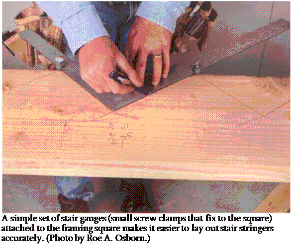
I use a framing square for stringer lay­out, and a simple set of stair gauges (small screw clamps that attach to the square) makes it easier (see the photo above). Screw one gauge at 71A in. (the unit rise) on the tongue, or narrow part, of the square, and the other gauge at 10 in. (the unit run) on the blade, or wider part. Begin the layout at the bot­tom end of the stringer with the blade downward. Mark across the top of the square with a sharp pencil and label this riser #1. Slide the square up and mark the next riser #2, and so on. Take your time and work accurately, making sure

Calculating individual risers and treads

that each time you slide the square, you have the tread mark directly on the last riser mark so that each tread and riser are the same (see the drawing above).

I once built a set of stairs without using stair gauges. In the middle of the stringer, I made a mistake and laid out a riser at 8 in. instead of 7 in. Easy enough to do. I set the stringers and sheathed the treads and risers. When I walked up the completed stairs, I tripped on the 8-in. riser. I had the pleasure of building this set of stairs twice. Codes do allow for a bit of variation though. Even stairs don’t have to be built to perfection.

Riser height can vary up to Vie in. from step to step, for example.

Often the stringer is attached to the upper floor system, one step below the level of the upper landing (see the draw­ing on p. 1 60). This means that the step to the landing makes the 15th riser, so lay out 14 risers on the stringer. Once the risers and treads have been marked on a stringer, finish with a level mark at the bottom of the first riser and a plumb mark at the end of the last tread (see the drawing above).

Now give the stringer a 1 – in. back cut to make the treads 11 in. rather than 10 in. wide. This back cut doesn’t change the total run, but it does change the look of the stairs by tipping the riser back and providing a wider (and safer) tread. Back cut the risers by slipping the riser gauge down the blade until the tongue of the square rests 1 in. in from where the riser mark meets the tread mark. Remark all the risers, making them slant back. The uppermost tread needs to be extended 3A in. to allow for a riser board to be nailed against the landing header (see the drawing on the facing page).

MAKING A DRYWALL-PANEL LIFTER

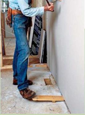
MAKING A DRYWALL-PANEL LIFTERThis small lever comes in handy when you’re installing the bottom course of drywall panels. By wedging the beveled edge of the tool un­der a bottom panel and stepping on the outboard end, you can lever the bottom panel against the bottom edge of the top panel and hold it there until you drive a few fasteners. Although you can buy a panel lifter, it’s easy to make one. Cut a piece of 1×4 about 16 in. long, then cut a taper on the flat face at one end. If the drywall must be lifted more than 3/i in., add a piece of 1 x2 to the bottom of the lifter.
Подпись: TYPICAL FASTENING SCHEDULES FOR DRYWALLMAKING A DRYWALL-PANEL LIFTER

Install J-bead

Window trimmers and headers are often wrapped in drywall. The same is true of trim­mers and headers in closets where bifold or bypass doors will be installed. In these loca­tions, drywall can replace the wood jamb as the finished surface. This is a good place to use up some of the scrap you’ve created. I try to select straight factory edges to go against the window frame. But other builders install vinyl J-bead trim where the drywall meets the window frame (see the illustration on p. 226). Nail the J-bead to the trimmer, then slip the drywall into the J-channel. This is an easy way to obtain a clean, straight, durable drywall edge.

I also install drywall about 2 in. up the attic access hole and cap it with J-bead. This leaves a trim surface on which the lid can rest. The lid can be made from a piece of drywall with several layers of rigid-foam board glued to the back for insulation.

STEP 4 INSTALL THE CORNER BEAD

Once all the drywall is in place, metal or vinyl corner bead is installed on all outside corners, including wall corners, window wraps, closet doorways, and the attic access hole. This bead protects corners from impact and forms a

Check for covered wall outlets. When installing drywall, it’s easy to overlook electrical outlets and fasten a panel right over these small boxes. As you’re installing panels, look in the usual places to make sure the outlets haven’t been covered. Check for receptacles ev­ery 6 ft. or so along walls near the floor and above kitchen countertops. Alsocheckforlightswitches near doorways.

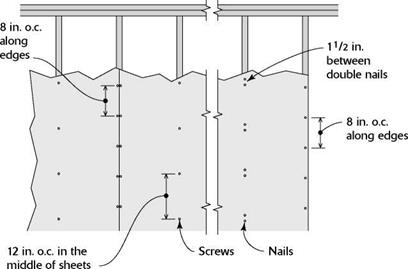
When using nails instead of screws, you may be required to double-nail.

MEASURING AND LAYOUT

Whenever possible, hold a trim piece in place and use a pencil or a utility knife to mark the cut-line. This is usually more accurate than transferring tape-measure readings.

Tape measures are frequently used to measure trim longer than 6 ft. Check your tape measure to be sure that the hook at the tape end isn’t bent and that the rivet slot hasn’t become elongated from the hook’s repeated slamming into the case—either of which will give inaccurate read­ings. However, for best accuracy, start measure­ments from the 1-in. mark, remembering to deduct 1 in. when taking readings.

A 6-ft. folding rule with a sliding-brass exten­sion is best for readings less than 6 ft. because the rigid rule won’t flop around as a tape meas­ure will. Unfold the rule to its greatest length
between two points and slide the extension the rest of the way. Then hold the extended rule next to the trim stock and mark the cut-line.

A framing square held against a door or win­dow frame quickly tells if it’s square or not— a good practice when sizing up a trim job.

A combination square is both a square and a 45° miter gauge, so it can be used to mark square and miter cuts. Because its ruler can be extended from the tool body and fixed with a screw, the square can double as a depth or marking gauge. The combo also has a bubble-level insert for lev­eling small surfaces such as windowsills.

An adjustable (sliding-T) bevel copies and transfers angles accurately. Because frame cor­ners are rarely 90° exactly, use an adjustable bevel to record the angle needed and then make miter cuts that bisect the actual angle.

Levels, 2 ft., 4 ft., and torpedo, should be part of any finish carpenter’s tool chest; use smaller levels in tight spaces.

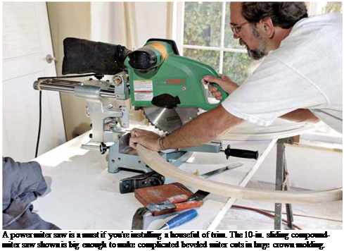
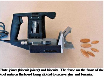
Подпись: TIPПодпись: For razor-smooth cuts and tight joints, buy an 80-tooth carbide-tipped blade for a 10-in. power miter saw or a 100-tooth blade for a 14-in. saw. If you save such blades for finish work only, they'll last a lifetime. 1111 Подпись: A power miter saw is a must if you're installing a houseful of trim. The 10-in. sliding compound-miter saw shown is big enough to make complicated beveled miter cuts in large crown molding. Подпись: Plate joiner (biscuit joiner) and biscuits. The fence on the front of the tool rests on the board being slotted to receive glue and biscuits.

Buy or borrow a laser level if you need to set cabinets at the same height or align different trim elements in a room.

CUTTING

Which tool you choose depends on how much trim you’ll cut. Wear safety glasses and hearing protection when operating any of these tools.

A miter box with a backsaw will suffice if you are casing only a doorway or two. A backsaw has a reinforced back so its blade is rigid; it should have 12 teeth per inch (TPI) or 13 TPI, with minimal offset (splay), so it cuts a thin kerf. Also useful: a dovetail saw (a small backsaw with 20+ TPI) and a slotting saw, whose kerf is even finer because its teeth are not offset.

Buy a power miter saw if you’ll trim at least one room or several casings. Well worth the cost, a power miter adjusts to any angle for miters (angles cut across the face of a board, with the blade perpendicular to the stock). A sliding compound-miter saw, though more expensive, is more versatile. In one stroke, this saw will cut a miter and a bevel (an angle cut across a board, in which the sawblade is tilted)—hence the name compound miter. It will also cut through wider stock such as wide baseboards or crown molding.

A table saw may be the only table tool you need if you are cutting only miter or butt joints. Table – saw guides are generally not as accurate or as easily to re-adjust as the guides on power miter saws, so recutting miter joints will be a bit more work. With a power miter saw, you clamp the stock steady and move the blade, whereas cutting a miter on a table saw requires feeding long pieces of trim at an odd angle to the blade.

Still, table saws be can a good choice for tight budgets because they can also cut stock to length (crosscut) and width (rip cut), prepare edges for joining, and cut dadoes (slots) easily.

A sliding miter trimmer (also known as a Lion Miter-Trimmer™) looks like a horizontal guillo­tine and bolts to a bench. Because its blade is razor sharp, it slices wood rather than sawing through it. Although it can shave off paper-thin amounts of wood till joints fit exactly, it’s been eclipsed by power miter saws for on-site trim installations.

A quality power jigsaw (sometimes called a saber saw) is indispensable for fitting and notch­ing wood, such as fitting thresholds around integral door stops.

Use a coping saw to cut along molding profile lines, ensuring a tight fit where molding meets in inside corners. For more, see p. 414.

A plate joiner (biscuit joiner) is a specialized saw with a small, horizontal circular blade that cuts slots into board edges. After slotting boards to be joined, inject glue and insert a football­shaped wooden wafer, called a biscuit, which will swell to create a strong joint with no need for nails or screws.

SHAPING AND SANDING

A block plane and a palm sander are probably all you’ll need unless you plan to shape board edges to create complex molding, in which case, get a router.

Block planes are most often used to trim miter joints for a tight fit. If you slightly back-bevel

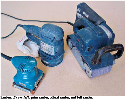
Подпись: Sanders. From left: palm sander, orbital sander, and belt sander. Подпись: a TIPSmiters, the edges of the face will make contact first. Block planes can also shave down a door or window jamb that is too proud (too high above the wall plane), thereby allowing the trim to lie flat. A power plane (see the photo on p. 167) can do everything a handplane can but more aggres­sively, so practice on a piece of scrap and check your progress after each pass. Caution: Before planing existing trim, first use a magnet to scan the wood for nails or screws, setting them well below the surface before planing.

Rat-tail files and 4-in-1 rasps (see the bottom photo on p. 40) remove small amounts of wood from curved surfaces, so that coped joints fit tightly.

Routers are reasonably priced and invaluable for edge-joining, template cutting, mortising, and flush trimming when used with a table. Router tables vary, but on most you mount the router

Handplanin

When handplaning, clamp the wood securely, and push the tool in the direction of the grain. While holding the shoe of the tool flat against the edge of the wood, angle the tool’s body 20° to the line of the board, so that the plane seen from above looks like half of a V. At this angle, the plane blade encounters less resist­ance and clears shavings better.

upside-down, to the table’s underside, so the router bit protrudes above the tabletop. A guide fence enables you to feed stock so that the router bit shapes its edges uniformly—much as a large shaper in a lumber mill would.

Before setting up a router table, however, read up. Fine Woodworking magazine’s Web site (www. taunton. com/finewoodworking) has hun­dreds of references on routers and router tables. Above all, heed all safety warnings about routers: Their razor-sharp blades spin 10,000 rpm to 30,000 rpm.

Sanders are needed for a variety of jobs. A palm sander (or block sander), is useful for shaping contours and sanding in tight places and for light sanding between finish coats. Orbitalsanders are intermediate in cost, weight, and power. Random orbital sanders sand back-and-forth and orbitally (the center of the sander’s pad shifts constantly); they cut faster and leave fewer sanding marks.

If you buy only one sander, this is the one to get. Belt sanders are great for preparing stock and stripping old finishes, but they are so powerful that they tend to obliterate details, so use them sparingly. A belt sander is particularly useful for fitting scribed cabinet panels, as shown in the top right photo on p. 311. Whatever the size of the sander, change the paper often; you shouldn’t need to lean on a sander to make it cut.

Rut Depth Predictions

A first series of ORNI calculations was performed considering only the rutting of the UGM layer, and assuming different temperatures in the bituminous wearing course (between 15° and 35°, corresponding approximately to the range of temperatures measured in-situ). The results are presented on Fig. 11.18. It can be seen that the temperature in the bituminous wearing course has a large influence on the permanent deformations of the UGM (the temperature affects the modulus of the bituminous material and, therefore, the stresses transmitted to the granular base).

12

Figure 11.19 presents the results of a second series of calculations where the rutting of the subgrade soil was also taken into account. The contribution of the subgrade to the total rutting is important, representing about 40% of the total rut depth. The final rut depths obtained after 1.5 million loads, with the contribution of the subgrade, are close to the experimental measurements, especially for the temperatures of 23° and 27°, which are close to the average in-situ temperatures. However, the model predicts a too rapid stabilisation of the permanent strains in comparison with the experimental measurements.

Test Results

Durability tests of asphalt mixtures, especially those intended for wearing courses, have become commonly used around the world (Hobeda, 2000; Sybilski and Mechowski, 1996). The above-average durability of SMA has been emphasized in numerous publications so they will not be described here. This durability is the result of a high binder content and a thicker binder coating on an aggregate that has the same content of air voids as AC.

BASES

Breakaway luminaire poles are designed to yield at their base attachment to the foun­dation. There are numerous types of bases currently in service. Some of these are designed for breakaway operation and others are not designed to yield. The nonyielding types have application where vehicle speeds are low and the danger from a falling pole is greater than the hazard of hitting the rigidly mounted pole. A description of the most common base types follows. Not all of these bases are crashworthy.

Direct Burial Base. The direct burial base allows the pole to be directly embedded in the soil. It is the most economical, since it eliminates the need for a foundation. It is the common type of base for wood and is used frequently with concrete and fiberglass reinforced plastic (FRP) poles. FRP poles are the only direct burial poles currently approved for breakaway use. The other types are normally limited to low-speed facili­ties or should be located out of the recoverable area.

Flange Base. Most steel and aluminum poles are fitted with a plate or flange at the base of the pole. With steel poles, this usually involves welding a steel plate to the bottom of the pole. With aluminum poles, a cast-aluminum shoe base is usually fitted to the bottom of the pole. The use of a flange base implies that the flange is to be fas­tened directly to the anchor bolts embedded in the foundation or to some type of breakaway device. When a flange is in direct contact with the concrete, some method needs to be employed that will allow water to flow out and not be trapped in the base of the pole. Trapped water can cause premature failure of the pole due to corrosion on the inside. Flange base designs without breakaway features are not crashworthy and should be restricted to where the hazard from a falling pole is greater than the hazard of impacting the rigidly mounted pole. A flange base is illustrated in Fig. 7.73.

FIGURE 7.73 Flange-type steel base.

FIGURE 7.74 Frangible-coupling luminaire support.

Cast-Aluminum Transformer Base (T-base). T-bases may be steel or cast alu­minum and were originally devised to house the transformer. The T-base (Fig. 7.70) proved unacceptable for storage of the ballast because of moisture and insect damage to the electrical components. However, the cast base proved to have safety advantages, since it yielded and broke apart upon impact. The ballast is rarely stored in the base anymore, but the T-base is still frequently installed because it serves as an electrical junction box and because of its breakaway characteristics.

Frangible Couplings. A number of manufacturers have developed cast and extruded aluminum frangible couplings. The typical coupling (Fig. 7.74) is a short connector attached to the foundation on the bottom and the flange of the pole on the top. Upon impact, the coupling fractures, separating the pole from the foundation. The proper performance of frangible couplings requires proper matching of coupling and pole. Stiffer poles work best with frangible couplings, since the stiffness of the pole results in impact forces remaining in the direction of impact (shear). Flexible poles, such as aluminum poles, bend upon impact, resulting in translation of some of the impact force to vertical forces. This places the couplings in compression and tension, forces the couplings are specifically designed to resist. Frangible couplings often need to be enclosed in skirts to keep dirt and water from entering the conduit and to keep rodents from eating the wire insulation.

Slip Base. Luminaire support slip bases are designed to resist wind and vibration loads while safely releasing upon impact from any direction. A typical base consists of two triangular plates, one welded to the support pole and the other welded to the foun­dation attachment. The plates accommodate three anchor bolts and are slotted to allow release upon impact. If installed correctly, the foundation part of the slip base will be

• Any bolts used to anchor the foundation piece to the foundation must be lower than the plane of the slip base.

• The upper surface of the foundation piece must be no more than 4 in (100 mm) above the surface of the surrounding terrain.

• A keeper plate, 0.05 to 0.03 in (1.3 to 0.76 mm), must be placed between the sur­faces of the slip base to prevent the device from slipping apart in response to wind loads.

• Washers of sufficient strength to prevent deformations into the vee slots must be used between the plates and on the top and bottom.

• The bolts must be torqued to the specified level.

A four-bolt slip base (Fig. 7.75) is also available. Developed by Valmont Industries, it provides added structural resistance to environmental loads and is used extensively by some western states.

Shear Base. The design concept for the shear base is to load the rivets or welds that secure the base to a foundation plate. When struck by a vehicle, the rivets or welds are sequentially sheared and the support breaks away. Typical designs for shear bases are thin-walled stainless steel bases and a family of cast-aluminum bases (not T-bases).

Other. There are other breakaway methods that relate to specific materials used for the pole. These include a fiberglass-reinforced plastic pole with an anchor base that will break above a cast-aluminum base, and several schemes approved for use with aluminum poles.

FIGURE 7.75 Four-bolt roadway lighting support slip base by Valmont Industries.

Nonistanidardized Methods

These methods are normally based on similar assumptions—namely, in saturating a mixture with water (with or without negative pressure, that is a vacuum) and holding it there at a fixed temperature for a given time. Afterward, a strength test is con­ducted, most often using one of the following methods:

• Marshall stability

• Resilient modulus at different temperatures

• Indirect tensile strength

The comparison of results for specimens conditioned in water with those untreated in water determines the water resistance of an asphalt mixture.

In an extended variant, specimens saturated with water are subjected to many cycles of freezing and thawing to find the mixture’s susceptibility to water and frost. Another variant that involves freezing specimens previously saturated with an aqueous solution of NaCl (e. g., 2%) has also been used. This is a much more effective test due to the aggressive action of the aqueous solution of salt on binder adhesion to the aggregate. This kind of test is often conducted in countries with colder climates.

The Yellow River, a terrible friend

The first historical treatise from China dates from around 100 BC. This is the work of Sima Qian,[382] who had an official position in the court of the Emperor Wudi of the Hans at the beginning of the imperial era. Sima Qian revived and perpetuated the legendary attribution of the ancient course of the Yellow River to Yu the Great, undoubtedly with some measure of exaggeration. He gives us a rather precise description of the ancient course (Figures 8.2 and 8.3):

“The documents of the Xia Dynasty tell us that Emperor Yu spent thirteen years controlling and bringing an end to the floods and during that period, though he passed by the very gate of his own house, he did not take the time to enter.

Of all the rivers, the Yellow River caused the greatest damage to China by overflowing its banks and inundating the land, and therefore he turned all his attention to controlling it. Thus he led the Yellow River in a course from Jishi past Longmen and south to the northern side of mount Hua; from there eastward along the foot of Dizhu mountain past the Meng ford and the confluence of the Lo River to Dapei. At this point Emperor Yu decided that since the river was descending from high ground and the flow of the water was rapid and fierce, it would be dif­ficult to guide it over level ground without danger of frequent disastrous breakthroughs. He therefore divided the flow into two channels, leading it along the higher ground to the north, past the Jiang River and so to Dalu. There he spread it out to form the Nine Rivers, brought it together again to make the backward flowing river (this is the lower portion of the river which has tidal influence), and thence led it into the gulf of Bohai.”[383]

The reader may note that the great historian recognizes the hydraulic consequences of the change of slope where the river flows out onto the plain, as well as the effects of the tide. These were surely personal observations, for Sima Qian had traveled all across China.

The Yellow River owes its name to the color of the sediments it carries. During floods it is nearly a river of mud, having one of the world’s highest concentrations of sediment. Nearly 5,500 km long, in its middle reaches it flows for 1,200 km across a plateau of loess, carrying fine sediments deposited by the wind. Once the river arrives on the plain, its bed slope suddenly decreases and the water velocity is consequently reduced, as is noted by our historian.[384] [385] As the water velocity decreases, the particles in suspension deposit onto the bed.

Since very early times the Chinese have constructed dikes to protect villages and fer­tile lands from the floods. The deposited sediments accumulate between these dikes, and

21

this of course raises the bed of the river relative to the plain surrounding it. Quite

rightly, Chinese tradition emphasizes both the importance of dredging the riverbed dur­ing low-water periods and the importance of building dikes. As we have seen in Chapter 1, it was in dredging the bed of the river that Yu succeeded in conquering the waters; his father Kouen, who only built dikes, had failed in trying to contain the river.

Failure to dredge the riverbed inexorably ends up causing an overflow and dike rup­ture. The river flows onto the plain with consequences that one can easily imagine, and it may then wander over large distances and establish a new course completely different from that in which it had formerly been contained by dikes. There have been nearly

2,0 dike ruptures recognized in Chinese history up to the present time, during which the course of the Yellow River has undergone 26 significant changes.[386] Over the course of history, the irrigated and fertile plain has become more and more densely populated – and therefore the consequences of inundation become more and more serious.

The Yellow River, a terrible friend

Figure 8.2 The principal historical courses of the Yellow River. N. B. Between 168 and 132 BC, the river flows into the Huai to the south. Moreover, courses 2 and 3 most often comprised two distinct arms each. Finally, it is probable that courses 5 and 7 existed since 1187, and that courses 5 and 6 functioned up until 1495. Other temporary arms are not shown on this map.

The principal flood events took place between the 2nd century BC and the beginning of the Christian era (Figure 8.9), then again between the 11th and the 14th centuries, when the Yellow River flowed to the south of Shandong and joined the Huai. It is not until the 19th century that the river comes back to the north, in the bed of the Ji river. From the beginning of the Qin and Han Empires, Chinese history records multiple examples of populations that are ruined and displaced by floods, eventually to be resettled by the cen­tral authority in colonized regions at the edges of their former domains.[387]

Irrigation and transport works in the feudal period

Case Study: The Sunroom at Earthwood

I

’ve been practicing “timber framing for the rest of us” since 1975, but I never thought I’d write a book about it, so I wasn’t careful about photographing the methods. When students at Earthwood said they really wanted a book on the subject, Jaki and I decided to build a second-story sunroom. We didn’t really need the space, but figured that it would be a great photo opportunity for the book. Also, the ceiling was leaking in the room below the existing sitting deck and we needed a project for cordwood workshops, so we figured we had enough reasons build it. Now it’s our favorite room, especially on sunny winter days.

With the book in mind, I deliberately used a variety of timber-framing techniques.

Design Overview of the Project

I have renovated old houses and started from scratch building new ones. Starting from scratch is easier.

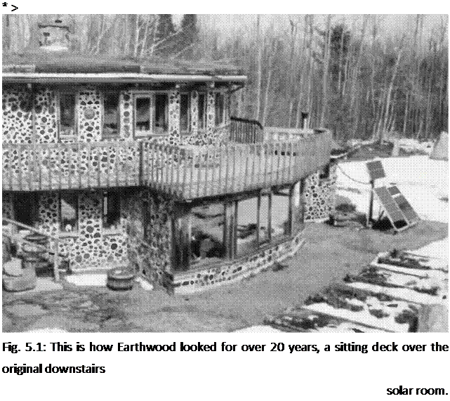
We built a downstairs solar room within a year of Earthwood’s completion in 1981. (Fig. 5.1). The room shared a common wall with the curved cordwood masonry wall of the home, the curvature flattened somewhat by a six-foot-wide (1.8-meter-wide) sliding glass door. The east and west walls feature cordwood, a door, and a small window. The long well-posted south wall is mostly thermalpane glass. A six-by-ten girder — or girt — supported the radial four-by-eight ceiling joist system which extended through the solar room. These joists also supported an outdoor sitting deck of two-by-six pressure-treated planking. Between the ceiling joists, we had installed corrugated fiberglass panels, gently sloped to the south. Rainwater dripping through the deck boards fell onto the panels and was carried away, where it dripped harmlessly onto a crushed stone walkway below. For insulation, we installed extruded polystyrene to the underside of the ceiling joists.

All of this worked fine for a few years, but mice found their way into the space over the insulation, as they are wont to do in the country, and, after a while, the corrugated fiberglass began to leak slightly. After twenty years, the insulation was smelly and in bad shape, a combination of mouse mess and moisture. Something had to be done, whether we built a new room over the top or not.

Подпись: * > Fig. 5.1: This is how Earthwood looked for over 20 years, a sitting deck over the original downstairs solar room. Jaki and I tore out the rigid insulation and the one-by boards that supported it, only to discover that the four-by-eight joists were in bad shape. One or two of them might have been saved, but we decided to replace the lot. The new ceiling joists would be left uncovered — insulation would not be necessary with a finished room upstairs — and we wanted the room to look nice. New tongue-in-groove planking might as well be supported by fresh-smelling and unstained ceiling joists. Building the new sunroom also meant reclaiming the old one, doubling the advantage of space gained.

Adjusting Reference Lines

It is common that concrete foundations or slabs are not the exact dimensions that are shown on the plans. These need to be identified and corrected.

Common sense and experience are the best decision-making tools for approaching and correcting errors. Once you have your footprint sketch with the dimensions and square checks on it, you’ll be able to determine if there are any errors.

If a diagonal line is too long, then some of the lines at the end of the diagonal must come
in to make the diagonal the right length. (See “Square Correction" illustration.) Check the wall dimensions lines to see which lines can be shortened. Once you’ve determined the best way to make adjustments, speak to the superintendent about your suggestions. Typically, a fix will involve moving the wall in or out on the concrete foundation.

Depending on the finish, there is a certain tolerance that will allow for moving the walls without
affecting the appearance. It is common to have finish material that overhangs the foundation, so moving the wall out slightly may not be noticeable. It is also common to have the sheathing on the outside of the foundation, so that if the wall needs to come in, it can be adjusted in the thickness of the sheathing without affecting the look of the finish.

If corrections would cause visible errors in the finished building, then consider alternative measures. An example of a visible error would be if the concrete finish wall sticks out past the siding on the finished exterior wall. There are three methods that can be used to address errors in the foundation. These are as follows:

• Correct the foundation wall. This is the best solution, but often cost-prohibitive.

• Change the dimensions of the building. This is easy, but very often causes problems later on. Make sure to check that the change does not affect truss span if using roof trusses.

Also, check to see that the change does not affect dimensions of items such as bathtubs or cabinets. If a change is made, make sure it is made on all copies of the plans.

• Do not correct the errors. Correcting the errors might cause more problems or imperfections in the building than the errors will.

The “Footprint Sketch Dimensions" illustration is made on the job site. It will help determine how to best adjust your reference lines to make the building square. In this example, four dry lines are established to form a square. The diagonal distances that should be the same are then checked. Because they are different, the reference lines will need to be moved to make the diagonals the same. By comparing the actual and the planned dimensions of the walls that the reference lines are measured from, you can determine which reference lines should be moved. When you move a reference line, the other lines are affected.

If you have all the information down on your footprint sketch, you can come pretty close to knowing exactly how much to move each line, and keep making adjustments until you are comfortable with your accuracy. Once your reference lines are established, you can set all the other lines in the building from them. The measurements in circles on the sketch show the distance that the reference lines would be first moved. It is difficult to determine exact amounts because of the proportions, but if you study the footprint for a little while, you can come pretty close.

Checking level using a rotary laser.