Plan panel installation

It’s smart to plan an installation sequence when there are a number of walls to finish with drywall. Determining which walls to cover first, and how panel layout will work, saves time and aggravation. Here are some tips to help you plan the installation sequence for walls:

HANG PANELS HORIZONTALLY. By installing 12-ft. panels horizontally, you greatly reduce the number of joints in a wall. The top panels

should be hung first. Don’t worry if the bot-

*

tom panel doesn’t extend all the way to the subfloor; this small gap will be covered by the baseboard trim. For rooms with 9-ft.-high walls, use 54-in.-wide drywall panels instead of the standard 48-in.-wide panels.

START ON CLOSETS FIRST. Check to see whether there are any closets that must be drywalled before working on long walls. Sometimes it’s easier to get large drywall pieces into a closet through a wall rather than through the closet door. Don’t bother cutting and installing small pieces of drywall to com­pletely cover a closet. You can do that later

PROPER DRYWALL INSTALLATION ON 2×4
INTERSECTING WALLS USING 2×6 BACKING


with scrap pieces cut from the long sheets. At this stage, you just want to have an easier time getting big pieces into the closets.

WORK FROM THE OUTSIDE IN. I like to drywall exterior walls before interior walls. Leaving the interior wall framing open when you start gives you greater freedom to maneuver the panels. To maximize this freedom, drywall the interior hallways last.

PAY ATTENTION TO BACKING AT WALL INTER­SECTIONS. As shown in the top illustration at right, backing can sometimes determine which wall should be covered with drywall first. When 2x6s have been used for backing where 2×4 walls intersect, there will be only a 1-in.-wide nailing surface for attaching dry – wall. In this situation, always install the inter­secting walls drywall after the other wall has been covered. Butt the intersecting wall’s panel tightly against the adjoining wall panel to make a solid corner.

Install the panels

As mentioned earlier, the top panels should be installed first. It’s important to butt the top edge of each wall panel snugly against the ceil­ing drywall. To make installation easier, you can start a few nails near the top of a sheet before you raise the panel into position.

Although I drive a few nails just to hold a panel in place, I like to use screws in the rest of the sheet on both ceilings and walls. Screws hold better, resist popping when framing lum­ber shrinks, and can be installed quickly once you get into the rhythm of using a screw gun.

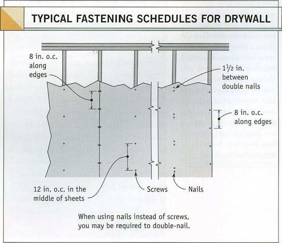
If you use nails in the middle of a panel, code may require that the panels be double-nailed (see the bottom illustration at right).


PLAN VIEW


Уг in.


Plan panel installation

2×6

backing


WRONG

You’d only have a V2-in.-wide nailing surface if you install drywall on the intersecting wall first.


RIGHT

If you install drywall on the exterior wall first, you will have a 1-in.-wide nailing surface.


Intersecting wall


ж


Plan panel installation

Подпись: Tool Talk MAKING A DRYWALL-PANEL LIFTERПодпись:Подпись: bottom course of drywall Подпись: Helping HandПодпись: Check for covered wall outlets. When installing drywall, it's easy to overlook electrical outlets and fasten a panel right over these small boxes. As you're installing panels, look in the usual places to make sure the outlets haven't been covered. Check for receptacles every 6 ft. or so along walls near the floor and above kitchen counter- tops. Also check for light switches near doorways.

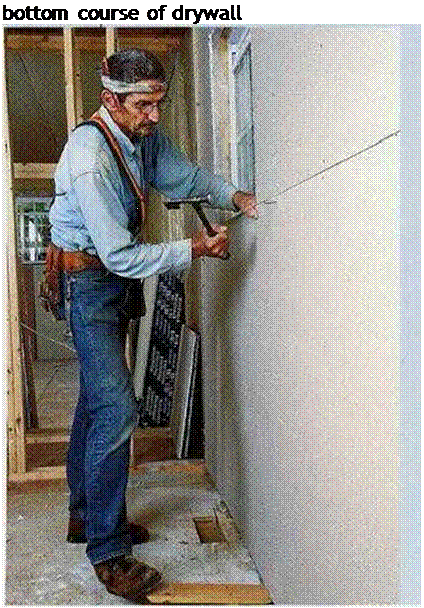
panels. By wedging the beveled edge of the tool under a bottom panel and stepping on the outboard end, you can lever the bottom panel against the bottom edge of the top panel and hold it there until you drive a few fasteners. Although you can buy a panel lifter, it’s easy to make one. Cut a piece of 1×4 about 16 in. long, then cut a taper on the flat face at one end. If the drywall must be lifted more than % in., add a piece of 1×2 to the bottom of the lifter.

When fastening a panel, work from the center to the outside edges. If you do use nails, drive the first set, then go back later and drive the second set, making sure the drywall is tight against the wall framing. When driving nails, it’s always advisable to push the panels tightly against the wall.

When hanging the bottom row of drywall, stagger the end or butt joints, just as you did on the ceiling. The bottom panels can be placed against the wall, then raised and held in place against the top sheet with a drywall lifter, allowing you to concentrate on fastening the sheet (see the sidebar above). Long sheets can be raised with a drywall lifter at each end.

Try to keep butt joints away from the cen­ter of the wall so that the joints will be less obvious. Also, have a sheet break over a door or window rather than right at the edge of a king stud or trimmer. A joint at the edge of a
door or window increases the likelihood of a crack in the drywall as the wood dries. Run panels all the way across doors and windows when you can, then cut them out later with a saw or router. You can also run a panel past an outside corner, then cut it flush with a utility knife after the panel has been fastened in place. This eliminates the need to measure and mark the panel.

Install 3-bead

Window trimmers and headers are often wrapped in drywall. The same is true of trim­mers and headers in closets where bifold or bypass doors will be installed. In these loca­tions, drywall can replace the wood jamb as the finished surface. This is a good place to use up some of the scrap you’ve created. I try to select straight factory edges to go against the window frame. But other builders install vinyl J-bead trim where the drywall meets the window frame (see the illustration on the fac­ing page). Nail the J-bead to the trimmer, then slip the drywall into the J-channel. This is an easy way to obtain a clean, straight, durable drywall edge.

I also install drywall about 2 in. up the attic access hole and cap it with J-bead. This leaves a trim surface on which the lid can rest. The lid can be made from a piece of drywall with several layers of rigid-foam board glued to the back for insulation.

EN 12697-12 Method

This EN 12697-12 method test is conducted on cylindrical specimens prepared in a laboratory (in a gyratory compactor, using a Marshall hammer) or cored from a slab cut out of a pavement. Specimens of 100 ± 3 mm, 150 ± 3 mm, or 160 ± 3 mm in diam­eter may be tested. When testing specimens 100 mm in diameter (compacted using a Marshall hammer, for instance), only mixtures with a gradation not larger than 0/22 mm can be tested. The set of specimens (minimum of six) of an asphalt mixture is divided into two groups. Both groups should be prepared at approximately the same time (within 1 week or less of each other). Half of the specimens are stored without conditioning, while the other half are subjected to conditioning in water. Specimens are compressed in an indirect tensile test using EN 12697-23. The compression test may be conducted at a selected temperature within a range from 5-25°C.

The standard introduced an index called the indirect tensile strength ratio (ITSR) as a measure of the water resistance of an asphalt mixture, expressed in percent. Apart from the ITSR index, the type of failure, the degree of coating of an aggregate with a binder in a brittle fracture, and the type of aggregate breakage should be given in a test report.

AASHTO T 283 Method

The AASHTO T 283 method involves conducting tests on a comparable set of speci­mens in an original (unconditioned) state and after conditioning and then comparing the results. In some literature this test is also called the modified Lottman test.

Appropriately prepared specimens are divided into two sets. One set is designed for testing without conditioning, while the other is subjected to conditioning in water and freezing. Both the original and conditioned specimens are tested with an indi­rect tension apparatus. The ratio of the conditioned tensile strength to the strength of the original specimens is called tensile strength ratio (TSR). TSR is usually required to be greater than 70% or 80% (most often 80%).

Modelling Hypotheses

The pavement was modelled in 3D, considering visco-elastic behaviour for the bi­tuminous material, and the non-linear elastic Boyce model (Eq. 9.10) for the un­bound granular material and the soil. The material parameters for the bituminous layer were determined from complex modulus tests and the in-situ temperature of the bituminous layer was taken into account in the modelling. The parameters for the unbound granular material (UGM) and for the subgrade were determined from repeated load triaxial tests. For the UGM, tests were performed at 3 different wa­ter contents: 2.3%, 3.8% and 4.8%, corresponding to the water content variations observed on the site.

11.4.5.1 Modelling of the Pavement Response for Different Water Contents

A series of calculations was performed for the 3 load levels and the 3 moisture contents of the UGM at a constant loading speed of 68 km/h.

Figures 11.12 and 11.13 show comparisons between measured and calculated maximum longitudinal strains at the bottom of the bituminous layer (exx BB), and maximum vertical strains at the top of the UGM layer (ezz GNT), for the 3 load levels. The results show that:

The model predicts relatively well the strains in the granular layer (ezz GNT), and their non-linear increase with load level. The strains in the bituminous layer (exx BB) are slightly over-predicted.

The water content of the granular layer has a strong influence on the vertical strains in the UGM layer. Increasing w from 2.3 to 4.8% increases the strains by about 60%. The calculations with w = 3.8% lead to the best predictions, close to the mean of the experimental measurements.

The calculations with the 3 water contents led to a range of variation of the verti­cal strains in the UGM layer similar to the scatter of the experimental measurements.

Figures 11.14, 11.15 and 11.16 present additional examples of prediction of sig­nals of longitudinal and transversal strains at the bottom of the bituminous layer

Fig. 11.14 Comparison of experimental and predicted longitudinal strain exx at the bottom of the bituminous layer – load 65 kN

(exx and eyy), and vertical strains at the top of the UGM layer (ezz), for the load of 65kN. The results show that CVCR (with w = 3.8% for the UGM) predicts well the strain signals (strain variations when the load moves in the x direction). The experimental curves of exx and eyy at the bottom of the bituminous concrete are non-symmetrical, due to the viscosity of the material, and this is well predicted by the visco-elastic model.

Fig. 11.15 Comparison of experimental and predicted transversal strain eyy at the bottom of the bituminous layer – load 65 kN

x (m)

-2 -1.5 -1 -0.5 0 0.5 1 1.5 2

Fig. 11.16 Comparison of experimental and predicted vertical strain ezz at the top of the granular layer – load 65 kN

POLE TYPES

Poles are available in a number of materials. The advantages and disadvantages of each follow.

Steel. Steel poles are available in galvanized, painted, powder-coated, and weathering types, plus a combination of powder coating over galvanizing. Galvanized is the most popular of the steel types because of the comparatively low cost and extended life. Painted poles are used primarily when a color is desired, but they require continual maintenance. The powder coating over galvanizing serves the same purpose and requires little maintenance. Weathering steel poles offer enhanced aesthetics but pro­visions must be made for the rusty runoff.

Aluminum. Aluminum poles are popular because of their resistance to corrosion and the resultant low maintenance cost. They have an added advantage of being lighter in weight than most other types. Aluminum poles operate well as breakaway designs when impacted at the design height. Since they are less rigid than steel posts, however, aluminum poles can result in an increased probability of improper breakaway operation when impacted higher than the design height. Aluminum poles are also considerably more expensive than most other types.

Stainless Steel. Stainless steel poles are corrosion-resistant and relatively light­weight. Their high rigidity results in dependable breakaway operation upon impact. They are, however, considerably more expensive than the other pole types.

Fiberglass. Fiberglass-reinforced plastic (FRP) poles are approved for breakaway use both in the anchor base and in the direct burial series. Shaft lengths are currently limited to 47 ft (14.3 m), which means 39 ft (12 m) height for the direct burial series and the full 47 ft (14.3 m) height for the anchor base series. Advantages of FRP poles include no rust, no corrosion, no rot, lightweight, no additional breakaway device required, no maintenance, no electrical shock, and, for the direct burial series, no need for concrete foundation. FRP poles come in many decorative styles and several standard colors.

Wood. Wood is perhaps the least expensive of pole types, particularly in areas where trees are plentiful. They can be treated to resist deterioration from the environment and damage due to insects. The use of existing utility poles for luminaire placement has the advantage of reducing the number of poles on the roadside. The huge mass of wood poles, however, makes it difficult to design them as breakaway, and thus, wooden poles should not be installed on high-speed facilities.

Concrete. Concrete poles are popular in regions where cement and concrete aggre­gates are plentiful. One advantage to concrete poles is that they can be economical. Concrete poles cannot, however, be designed effectively to safely break away upon impact. They are extremely heavy even when made by prestressing concrete. Impacts with concrete poles result in extensive damage to vehicles and severe injury to occu­pants. Prestressed concrete poles, therefore, should not be used within the traversable area, unless shielded, on facilities with design speeds over 30 mi/h (50 km/h). Concrete posts can be a functional and economical type of support on local urban streets if proper consideration is given to placement.

Rejuvenating

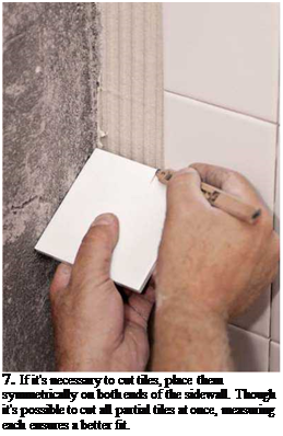
Подпись: 7. If it's necessary to cut tiles, place them symmetrically on both ends of the sidewall. Though it's possible to cut all partial tiles at once, measuring each ensures a better fit. Подпись: earlier. (This is also a good time to draw plumbed lines at either end of the back wall, indicating where cut tiles begin.) Next, use your story pole on the sidewalls, to see if it's necessary to cut tiles for them and, if so, where to place those tiles. In most layouts, a full column of tiles is placed along the outside edges of sidewalls because they are visually conspicuous; cut tiles are consigned to the corners. But if the back will have no cut tiles, consider putting full tiles in the inside corner of each sidewall. Also draw plumb lines to indicate the outside edges of sidewall tiles. Finally, you may want to draw additional layout lines to subdivide the back wall and anticipate tile cuts around the soap dishes, the tub spouts, the shower mixing valves, and so on. As with floor-tile installations, pros often begin setting tub surrounds in the middle of a tile field, where control lines intersect, setting a quadrant of full tiles at a time, then going back later—often, the next day—to cut and set partial tiles and trim pieces. It's also advisable to leave plastic tile spacers in place till the thinset cures. After pulling out the spacers with needle-nose pliers, you're ready to grout. Grout Joints and Caulking

If your grout is moldy, use a soft-bristle plastic brush to scrub the joints either with household cleaner, a weak bleach solution, or a tile-specific cleaner like Homax® Grout and Tile Cleaner. Wear rubber gloves and goggles, and always brush such solutions away from your face. If the mold returns, try installing a ventilator fan to reduce the moisture in the room. If the grout is intact but dingy, scrub, rinse, and allow it to dry before applying a grout colorant, which will both color and seal the grout. Follow the manufacturer’s instructions.

However, if tiles are loose; if surfaces flex; or if you see water damage around fixtures, at the base of a tub or shower, or along the backsplash of a counter, the substrate has probably deteriorated and should be replaced. In other words, you’ll need to tear out tiles and substrate.

There’s an interim condition, often caused by applying grout that was too thin or by over-sponging it, in which tile is intact but grout is worn or crumbling. In that case, use a grout saw to cut out the old grout, taking care not mar the tile edges. As you’ll realize quickly, this is a tedious job. Vacuum out the debris, scrub the joints with a cleaning solution, rinse well, and then use a grout float to apply polymer – modified grout, which will adhere better. It’s possible to regrout only part of a sur­face, but matching old and new grout color can be difficult, so it’s better to regrout the entire surface. Wait 72 hours, before sealing the grout joints.

Removing hardened caulk along the tub can be a chore. Chiseling it out is per­ilous because tub enamel and tile chip easily. Fortunately, acetone dissolves caulk. To use the acetone, cut cotton clothesline to the length of the caulk seam, wet the clothesline with acetone, and place it next to the caulking before covering both with duct tape. Left overnight, the acetone will soften the caulk. Caution: Acetone is volatile and thus flammable, and nasty to handle and breathe. Don’t use acetone around pilot lights, open flames, and the like. Wear rubber gloves and a respirator mask with cartridges.

Подпись: g TILESSupportin

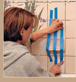
image831It’s smart to tape specialty tile pieces in place until their thinset has hardened. That’s especially true for heavy pieces, such as the soap niche shown, and for pieces with a relatively small bonding surface, such as bullnose edge trim. Caveat: Wait until the field tiles have bonded securely before taping to them.
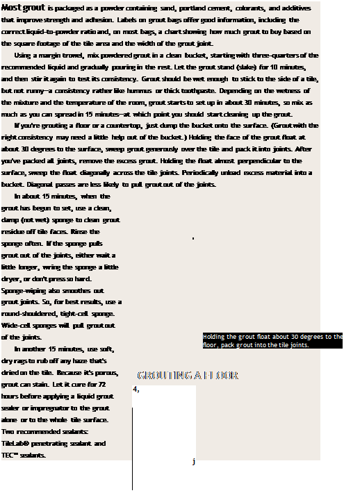
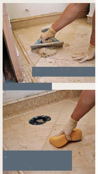
Getting Grout Right


Rejuvenating

In about 15 minutes, when the grout has begun to set, wipe the tile with a clean, damp sponge. Rinse and wring the sponge often. To avoid pulling grout out of joints, sweep the sponge diagonally across tile joints, using a sponge with tight pores.


image832

DURABILITY: WATER AND FROST RESISTANCE

Pavement durability is a broad term. Water and frost resistance of asphalt mix­tures have a disadvantageous effect on the mechanical performance of a course. Undoubtedly, the composition of a mixture—the type of aggregate, gradation of the mix, the type and quantity of binder, the presence of additives and the content of air voids—has an impact on this resistance. More information on this issue may be found in different publications (e. g., Kanitpong and Bahia [2003]; Santucci [2002])

The most common assessment methods for water and frost resistance of asphalt mixtures can be divided into the following two groups:

• Standardized methods

• Method AASHTO T 283

• Method EN 12697-12

• Non-standardized methods (devised in research centers for particular or local use)

A description of other methods for testing durability of asphalt mixtures and more details of this subject can be found in various papers (Chen et al., 2004; Hicks et al., 2003; Judycki and Jaskula, 1999; Martin et al., 2003; Ulmgren, 2004).

Experimental Pavement

The experimental pavement structure is presented in Fig. 11.11. It had a length of 28 m, a width of 6 m and consisted of:

• a bituminous concrete wearing course, with an average thickness of 85 mm;

• a granular base (0/20 mm crushed gneiss) with an average thickness of 430 mm;

• a subgrade soil consisting of 2.5 m of mica-schist with a low modulus (around 30 MPa).

Asphalt concrete (85 mm)

Fig. 11.11 Structure of the LCPC experimental pavement

The instrumentation installed in this experimental structure included:

• strain gauges to measure longitudinal and transversal strains at the bottom of the asphalt layer;

• displacement transducers to measure vertical strains in the top 100 mm of the granular layer and of the subgrade;

• vertical pressure transducers at the top of the subgrade;

• thermocouples in the asphalt layer; and

• tensiometers, to measure suction in the granular base and in the subgrade.

The pavement was subjected to dual wheel loads. Different load levels (45, 65 and 75kN), and different loading speeds (3.4-68km/h) were applied during the experiment.

Location of Poles

The location of a lighting pole is partially dictated by the lighting scheme selected by the designer for a section of roadway. Using the conventional (cobra head) type luminaires requires the pole to be close to the travelway and therefore, unless it is behind a barrier, most likely to be struck by an errant vehicle. A median barrier-mounted pole is less likely to be struck, but occasionally an out-of-control vehicle will get high enough on the barrier to impact the pole. When this occurs, the danger to oncoming traffic will be increased if the pole is of a breakaway design. Because of this possibility, median-mounted poles are normally not designed as a breakaway type. The lighting scheme that incorporates offset and/or high mast luminaires is the least likely to create a hazard on the roadside, since the poles can be located 40 to 50 ft (12 to 15 m), or farther, from the travelway. In addition to reduced accident rates, this type of lighting reduces maintenance costs due to pole knock­downs.

Pole locations are influenced by the location of sign structures, overpasses, guardrail, roadway curvature, gore clearances, overhead power lines, drainage pipes, drainage structures, underground utilities, and the shoulder slopes, in addition to the luminaire capabilities. The lighting designer must evaluate the eventual consequences of safety, aesthetics, maintenance, and economics when selecting the pole locations. Safety considerations for lighting pole locations include

• Poles should be placed outside the clear zone whenever practical.

• Pole locations should consider the hazards in servicing the lighting equipment.

• Poles should be located to provide adequate safety clearance in the gore areas of exit and entrance ramps.

• Poles should be placed to minimize interference with motorists’ view of the sign, and the luminaire brightness should not seriously detract from sign legibility at night.

• Poles should not be placed where overhead signs will cast distracting shadows on the roadway surface at night.

• Poles on the inside radius of superelevated roadways should have sufficient clearance to avoid being struck by trucks.

• Poles should never be placed on the traffic side of guardrail or any natural or manu­factured deflecting barrier.

• Where poles are located in exposed areas, they should have an approved breakaway feature or device.

• Poles along the freeway should be located at least 4.6 m and preferably 6.1 m or more from the edge of the travelway and include a breakaway device unless located behind a barrier or guiderail or otherwise protected.

• Poles behind flexible or yielding type rails or barriers should provide the necessary clear distance for rail or barrier deflection. The design deflection distance of the particular barrier being used should be checked to ensure that vehicles impacting the barrier will not continue into the lighting support.

• Installing poles on the median, instead of the roadside, should be considered where median width is sufficient (on landscaped medians) and on top of properly designed concrete safety shapes present on narrow medians. Among the advantages with median-mounted poles are that one-half the number of poles are required, the quan­tities of conduit and cable are reduced, house sidelight is minimized, and visibility on the high-speed lanes is improved.

Clear zone is not a constant distance but varies on the basis of the design ADT, the design speed, and the slope, either positive or negative, of the shoulder. Clear zone dimensions are given in the AASHTO Roadside Design Guide [13]. (See Chap. 6.)

ROADSIDE SAFETY

The primary purpose of roadway illumination is to increase safety by enhancing night­time visibility. The net safety benefit from increased visibility is influenced by the hazard posed by the roadway lighting or luminaire support acting as a fixed object. If roadway illumination is not warranted, or if it is installed wrong, there is a strong pos­sibility that traffic hazards will be increased rather than reduced by providing illumi­nation. The AASHTO publication Roadside Design Guide requires the lighting designer not only to produce an effective, efficient lighting system but also to consider removing the hazards inherent in such a system [13]. The Roadway Design Guide stresses that safety should be enhanced by considering the following, in decreased order of desirability:

• Remove the hazard from the right-of-way

• Locate the hazard in a place less likely to be struck

• Provide a breakaway support

• Provide a barricade

The most common approach to meeting the safety requirement has been to provide a breakaway structure for the light poles. There are a number of devices that have been tested and approved by the Federal Highway Administration for this purpose, including

FIGURE 7.66 Highway lighting design at typical cloverleaf interchange. Conversions: 93 m = 300 ft, 152 m = 500 ft.

transformer bases, frangible couplings, slip bases, and various schemes applicable to a particular type of pole such as fiberglass and aluminum. All these devices will perform as prescribed, but it is up to the designer to use the proper device in the particular situation encountered for the project. The FHWA approval process evaluates only the structural breakaway performance of a tested device, not the structural strength or the possible elec­trical hazard introduced when a pole is struck. The lighting designer must become familiar with the structural load limitations of each tested device in order to match the weight, height, and wind loading demands of the luminaires with the strength of the device being considered. The designer should also consider methods to mitigate or elimi­nate the possibility that damaged electrical wires will be exposed after a pole is knocked down. In urban areas or other locations where pedestrians or cyclists may be in the area where a breakaway pole would fall if struck, breakaway supports are not recommended.