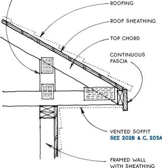
TRUSS WITH OVERHANGING EAVE
Exposed or Boxed-ln Eave
|
ENGINEERED HEEL TIED TO WEB SYSTEM OF TRUSS ALLOWS DEEP CEILING INSULATION SEE 198-199
|
|
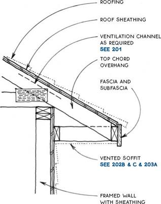
TRUSS WITH SOFFITED EAVE
TRUSS WITH SOFFITED EAVE
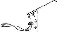
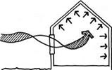
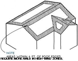
Because roofs are the highest part of a building and are the least weighted down by other parts of the building, they are the most vulnerable to the effects of wind. In areas prone to high winds, the design and detailing of roofs is one of the most critical concerns for the longevity of a building. The bracing of buildings to resist lateral wind forces is discussed in Chapter 3 (see 77 & 82).
Wind generally moves horizontally to impose lateral forces on buildings, much as earthquakes do. But wind flows in complex shifting patterns around a building, creating pressures on some surfaces and suction on others. Thus it can create vertical forces that actually lift the roof off a building.
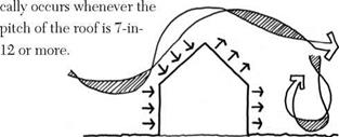
These vertical forces can be created in three ways. First, they may be produced as a negative pressure (suction) if developed on the leeward side of a building. In the case of a pitched roof, this condition theoreti-
A second way for wind to exert a vertical force on a roof is for the wind to catch a protrusion such as an eave or rake overhang. In this case, the force of the wind is localized at the edge of the roof.
Finally, wind can lift the roof structure from the inside of the building. This generally occurs as a weak point in the shell of the building such as a window or garage door giving way to the pressure of the wind. The wind suddenly enters the structure, pressurizing it and forcing the roof up.
To resist the force of high winds on roofs, several strategies may be employed. Some involve design decisions to minimize the impact of high winds in the first place, others involve strengthening what is built to minimize damage.
Design strategies—One basic strategy to increase a roof’s chance of survival in high winds is to keep the roof pitch low. High-pitch roofs extend higher into the sky, where wind velocity is greater, and present a greater surface area than do low-pitched roofs. Pitches between 2:12 and 7:12 are recommended for high-wind areas.
The shape of the roof also has a large impact on its durability in a windstorm. Generally, hip roofs fare the best because their geometry makes them self-bracing, and they have low eaves with no tall walls. Gable roofs present a weak point at the gable end itself, which is a tall vertical surface.
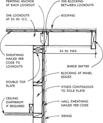
The width of overhangs at both eave and rake are important considerations for high-wind zones. Many buildings have been destroyed by winds that catch the underside of the eave and lift it off the building. Eaves of 8 in. or less are recommended for high-wind areas unless special measures are taken to anchor them.
Anchoring strategies—Assuming the building is shaped appropriately to withstand the force of high wind, it is still necessary to reinforce it beyond typical code standards. Framing members must be anchored to resist uplift and overturning, sheathing must be stronger, and fasteners must be increased. These measures are illustrated on the following page.
ROOF FRAMING FOR HIGH WIND
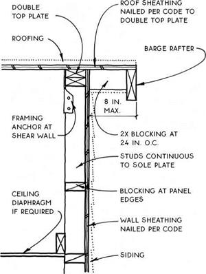

HIGH-WIND RAKE
Balloon Frame to Sheathing
HIGH-WIND RAKE
Balloon Frame with Lookouts
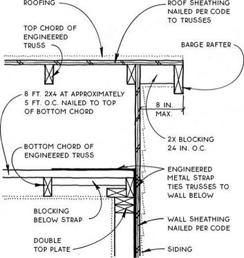


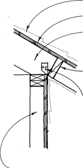 NOTE
NOTE
TOENAiLiNG (OR MORE FRAMiNG ANCHORS) TiE ROOF FRAMiNG TO DOUBLE TOP PLATE TO RESiST SHEAR FORCES PARALLEL AND PERPENDiCULAR TO WALL.
Platform Frame
Roof sheathing attaches to the surface of the rafters or trusses to form the structural skin of the roof.
It spans the rafters to support the roofing and, in the case of panel sheathing such as plywood or OSB, it acts with the walls to resist horizontal loads. Roof-sheathing material must be coordinated with the roofing itself, since each type of roofing has special requirements.
At exposed roof overhangs, the sheathing must be rated for exposure to the weather. The everyday sheathing used on the body of a roof is not rated for weather exposure, so when exposed eaves and/or rakes occur at the perimeter, a different (more expensive) weather-rated grade of plywood or OSB must be used. Solid board sheathing may also be used at these exposed locations.
The two basic types of sheathing are solid sheathing and open sheathing.
Solid Sheathing— Solid sheathing provides a continuous surface at the plane of the roof. This type of sheathing is necessary for composition roofing and built-up roofing, which have no structural capacity themselves. Metal, tile, and shingle roofing may also be applied to solid sheathing. For economic and structural (lateral-load) reasons, solid sheathing is almost always plywood, OSB, or other structural panels (see 163).
The structural panels act as a diaphragm to transfer lateral loads at the plane of the roof to the walls. When an exposed ceiling is desired, solid sheathing may
also be constructed of solid-wood tongue-and-groove boards. Tongue-and-groove sheathing, however, does not act as a diaphragm, so other methods of providing lateral-load stability, such as diagonal bracing, must be employed.
Open sheathing—Open sheathing, also called skip sheathing, is composed of boards spaced apart (see 166). This type of roof sheathing is used under wood shingles and shakes, which usually require ventilation on both sides of the roofing material. Open sheathing may also be chosen for economic reasons, but only if used with roofing systems such as metal or tile, which have the structural capacity to span between sheathing boards. Alternative methods of providing a roof diaphragm, such as diagonal bracing, must be used with open sheathing.
Combinations, of course, are also possible and often appropriate. For example, solid sheathing at exposed overhangs is often combined with open sheathing on the rest of the roof.
Recommendations—Sheathing recommendations for roofs by roofing types are as follows:
Composition and built-up roofing must be applied to solid sheathing because these roofing materials do not have the structural capacity to span between the boards of open sheathing.
Wood shingle and shake roofing is best applied over open sheathing because the spacing between the open sheathing allows the roofing to breathe from both sides, prolonging its life. Shingle and shake roofs may also be applied to solid sheathing at exposed eaves and rakes and similar locations. In some regions, the common practice is to place a moisture barrier over open sheathing to keep out wind-driven rain. In very windy areas, solid sheathing is often used. Consult with local codes and builders for the accepted practice.
Metal and tile roofing may be applied to either solid or open sheathing. Both roofing materials have the strength to span across open sheathing, but there is no advantage for either in having them breathe from both sides.
 ROOF SHEATHING
Introduction
NOTE


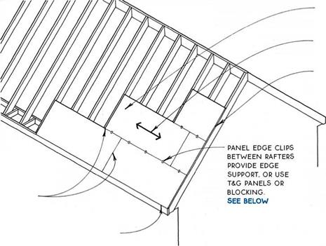
 most manufacturers specify a 1/8-in. space
BETWEEN THE EDGES OF pANELS TO ALLOW FOR
expansion. panels sized
FOR THIS Spacing ARE AVAILABLE. the gap may BE OMITTED IN VERY DRY climates., check WITH local codes & builders FOR accepted practice IN your area.
Panel installation—Low cost and ease of installation make plywood or OSB panels the sheathing of choice for most modern roofs. The system provides a structural diaphragm and is appropriate for all but wood shingle or shake roofing, which requires ventilation.
The standard panel size is 4 ft. by 8 ft., so rafter or truss spacing that falls on these modules is most practical. Care must be taken to protect panel edges from the weather by the use of trim or edge flashing (see 169C). Sheathing at exposed overhangs must be exterior or exposure 1-rated and must be thick enough to hold a nail or other roof fastener without penetration of the exposed underside.
Recommended fastening—Recommended fastening is 6 in. o. c. at edges and 12 in. o. c. in the field (6 in. in the field for supports at 48 in. o. c.). For sheathing spans greater than 24 in., tongue-and – groove edges, lumber blocking, or panel edge clips are required at edges between supports. Use two clips for spans of 48 in.
|

12 / 0 5/i6 in. 12 in.
16 / 0 5/i6 in. to 3/8 in. 16 in.
24 / 0 3/8 in. to У2 in. 24 in.
32 / 16 15/32 in. to 5/8 in. 32 in.
48 / 2 4 23/32 in. to 7/8 in. 48 in.
|
Notes—Values in the table above are based on APA – rated panels continuous over two or more spans with the long dimension of the panel perpendicular to supports. Verify span with panel rating. (For the APA rating stamp, see 48.)
Spans are based on a 30-lb. live load and 10-lb. dead load, the minimum rated by the APA—The Engineered Wood Association. Check local codes and with design professionals for higher loading such as greater snow loads or higher dead loads of concrete tiles or other heavy roofing. These ratings are minimum. For a more solid roof, reduce spans or increase thickness.
|
SOLID ROOF SHEATHING
Plywood & Non-Veneered Panels
|
|

NOTE


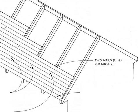
JOiNTS MAY BE MADE AT MiD-SPAN FOR SOME END-MATCHED DEckiNG. VERiFY NAiLiNG WiTH MANUFACTURER’S SpEcS. TOENAiLiNG AT MiDspan iS REquiRED for longer spans. VERiFy with manufacturer.
T&G sheathing (decking) is most often used for exposed ceiling applications. It can also be used selectively at exposed eaves or overhanging rakes. Rafters are spaced at wide centers since the decking will span more than 24 in. in most cases (see the table at right). Because this sheathing material does not provide a diaphragm at the plane of the roof, other means of bracing the roof against horizontal loads must usually be employed. For example, the roof may be braced with metal straps applied to the top of the sheathing or with a layer of plywood or OSB over the decking.
Insulation for an exposed ceiling must be located above the sheathing. Insulation will vary with climate and with roofing material. Rigid insulation is usually the most practical because of its thin profile, but it is more expensive than batt insulation. Batts are often chosen for colder climates, where the thickness of either type
|
EXPOSED T&G DECKiNG SPANS 1
|
|
Nominal thickness
|
Approximate span
|
|
2 in.
|
6.0 ft.
|
|
3 in.
|
10.5 ft.
|
|
4 in.
|
13.5 ft.
|
|
5 in.
|
17.0 ft.
|
of insulation (rigid or batts) requires adding a second level of structure above the decking to support the roof.
This table assumes a 30-lb. live load for Douglas – fir or southern pine species. The table is for comparison and approximating purposes only. The actual span capacity depends on roof pitch, species, live-load values, and end-joint pattern.
 SOLID ROOF SHEATHING
Exposed T&G Decking


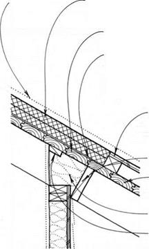


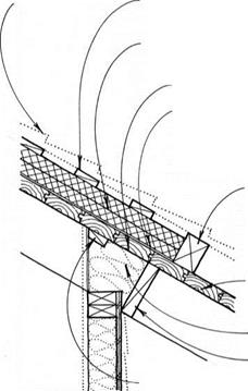
RIGID INSULATION OVER TEMPERATURE-CONTROLLED SPACE
T&G EXPOSED DECKING
insulation frieze block
NAILING BLOcK FOR FINISH wALL


Metal or composition roofing may be applied directly over rigid insulation on T&G sheathing. For this construction, fasteners must be sized to penetrate through the insulation but not through the decking.
Preformed metal roofing—Preformed metal roofing may be applied directly to the insulation over a layer of 15-lb. or 30-lb. felt. If the insulation is more than ЗУ2 in. thick, wooden nailers equal to the thickness of the insulation and parallel to the decking are recommended to provide a stable surface for roof fasteners. Nailers should be located 3 ft. to 5 ft. o. c., depending on the profile of the metal roofing.
Composition roofing—Composition roofing may also be applied directly if the insulation board is strong enough to withstand the rigors of the roofing process. Most asphalt-shingle manufacturers, however, will not honor their warranty unless the shingles are applied to a ventilated roof. Unventilated shingles can get too hot and deteriorate prematurely. The addition of vertical furring strips and sheathing over the insulation with vents at the top and bottom of the assembly will satisfy the requirement for ventilation.
EXPOSED T&G DECKING AT EAVE
Metal or Composition Roof
Wood or tile roofing requires another layer of material over the insulation. In some cases, it may be more economical to substitute nonrigid insulation.
Wood shingles or shakes—Wood shingles and shakes last longer it they are allowed to breathe from both sides, so they should be raised on furring strips above the level of the insulation. The furring strips may be nailed through the rigid insulation to the decking, or they may be attached directly to the decking between rows of insulation. The spaces and cracks between the shakes or shingles will usually provide adequate ventilation.
Despite the advantages of breathing, shingles should be installed over solid sheathing and underlayment in areas with extreme wind-driven rain or snow or if the roof pitch is as low as 3-in-12 or 3l/2-in-12.
Ceramic or concrete tiles—Ceramic and concrete tiles, like shingles, commonly require furring strips.
The furring strips should be spaced according to the length of the tiles (see 187B, 188, and 189).
EXPOSED T&G DECKING EAVE
Wood or Tile Roof
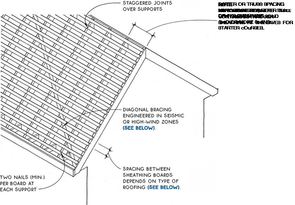
Open, or skip, sheathing is usually made with 1×4 or 1×6 boards nailed horizontally to the rafters with a space between the boards. Since this sheathing material does not provide a diaphragm at the plane of the roof, other means of bracing the roof against horizontal loads must be employed. Let-in wooden bracing or metal strap bracing applied to the top or bottom surface of the rafters will suffice in most cases. This bracing must be engineered in seismic or high-wind zones or for very large roofs. Bracing may sometimes be omitted on hip roofs because the shape of the roof provides the bracing.
Spacing for open sheathing depends on the type of roofing. The ability of the sheathing to span between
supports depends on the spacing and on the type of roofing applied over it. Check with local codes and with roofers for accepted local practices.
Wood shingles or shakes require spacing equal to the exposure of the shingles or shakes—usually about 5 in. for shingles to 10 in. for shakes. The sheathing is usually 1×4.
Concrete tiles, depending on the type, may be installed on open sheathing spaced in the 12-in. to 14-in. range. The roofing material is heavy, so 1×6 or 1×8 or 2×4 sheathing is practical.
Preformed metal roofing is lightweight and runs continuously in the direction of the rafters. In most cases, 1×6 sheathing at 24 in. o. c. is adequate.
@ OPEN ROOF SHEATHING
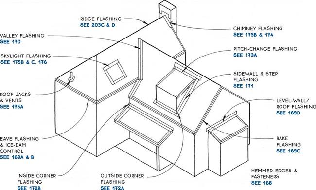
Flashing is a necessary component of most roofing systems. Flashing makes the roof watertight at edges, openings, and bends in the roof where the roofing material cannot perform the job alone.
Flashing materials and details must be coordinated with the roofing material to make a durable and waterproof roof. Although design principles are transferable from one type of roofing to another, proportions of materials may vary. For example, the details drawn in this section show a thin-profile roofing material such as asphalt or wood shingles, but flashing for thicker roofing materials such as tile or shake will have different proportions. Some of these special flashings can be found with the details for the particular roofing type.
You may want to use different flashing materials for roofs than for walls, because roofs are constantly exposed to the weather and, in most cases, are replaced much more frequently than walls. (For a discussion of wall flashing materials, see 102.) Moreover, roof flashing itself is not always replaced at the same time as the roof. Chimney or wall flashing may not be easily changed when the building is reroofed, so it should be made of materials like copper or stainless steel, which can last as long as the building. Valley or pitch-change
flashing will be easy to replace at the time of reroofing if the original roof is removed. This flashing may be made of material with a life span equivalent to the roof itself.
The flashing and its fasteners must be compatible with each other and with the roofing material itself. For example, flashing and fasteners for metal roofs must be compatible with the roofing metal to avoid galvanic corrosion. Flashing may be isolated from other materials with 30-lb. felt or bituminous paint.
The basic principle of roof flashing is to have the roofing, the flashing, and other materials overlap one another like shingles. Water running down the surface of the roof should always be directed by the flashing across the surface of the roof. Gravity will then work to direct water down the roof, away from the gaps covered by the flashing. This way, only wind-driven rain can force water through the roofing to the waterproof underlayment (see 177), which acts as a second line of defense. Each detail may have local variations to account for such weather-related factors. All flashing materials, therefore, should be discussed with local sheet-metal contractors or roofers.
 ROOF FLASHING
Introduction


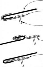
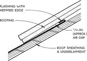
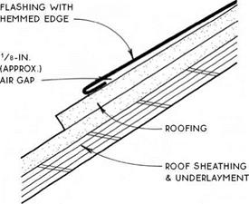
Hemmed edges—One very important detail for roof flashing is the hemmed edge, which folds back on itself about V2 in.
— –
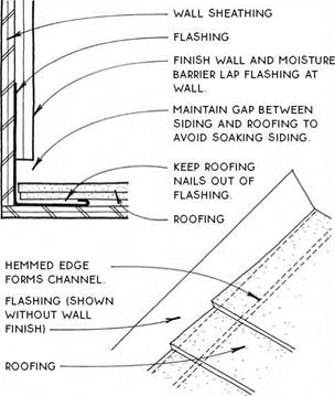
This fold makes the flashing thicker at the edge, which, aside from forming a stronger and neater edge when exposed, helps control the flow of water on roofs, as shown in the drawings on this page. Tucked under roofing, the tumed-up hemmed edge creates an air gap that prevents moisture from migrating between the roofing and flashing by capillary action.
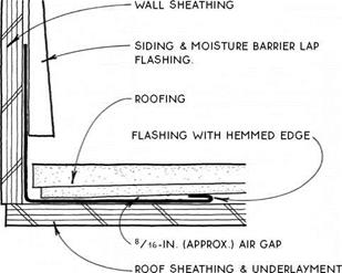
A hemmed edge also works when it is horizontal, as in sidewall flashing (see 171A & B), where the hemmed edge not only resists capillary action but also forms a barrier to water running down the flashing and thus keeps it from running onto the roof sheathing.
Turned down and lapped over roofing, the hemmed edge creates an air gap under the flashing that discourages capillary action. The hemmed edge can also form a seal on smooth surfaces such as skylight glass, which is only made more complete by the presence of water adhering by surface tension to the two surfaces.
Fasteners—Flashing is usually nailed to the structure. Nails are located at the edge of the flashing to avoid punctures in the flashing where it is designed to keep moisture from entering. Care must be taken to select nails that will not cause galvanic corrosion.
Another method of attaching flashing is the cleat, a small metal clip usually made of the same material as the flashing itself. Cleats fasten flashing to the roof without puncturing the flashing and allow for expansion and contraction of flashing metal without dislodging of
used to make concealed
FLASHiNG
 ROOF FLASHING
Hemmed Edges & Fasteners
ROOFiNG

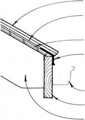
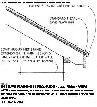
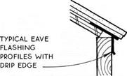
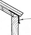 FELT uNDERLAYMENT LAPS OVER METAL EAVE FLASHiNG.
SHEATHiNG
METAL EAVE FLASHiNG WiTH DRIP LAPS FASCiA
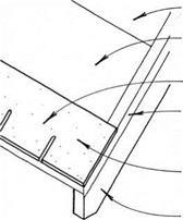


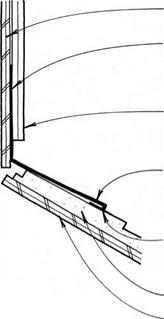

(& gutter).
 LEVEL WALL FLASHING


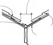
Valleys on roofs, like valleys in the landscape, collect the runoff of all the slopes above them. To handle such a concentration of water, valleys must be carefully flashed. Except when using roofing materials that can bend, such as asphalt shingles or roll roofing, valleys are usually flashed with metal flashing.
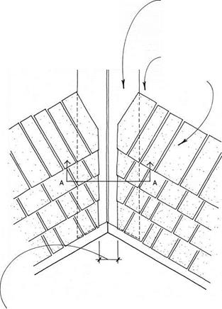
Open valley flashing is the most common and may be used with virtually all roofing materials. An open valley allows the runoff water to flow within the confines of the exposed metal flashing rather than over the roofing material itself.
|
NOTE
BITUMINOUS SHEET WATERPROOFING LAPS VALLEY FLASHING IN LOCATIONS WITH SEVERE WEATHER. SEE SECTION A-A AT LOWER RIGHT.
|
|
VALLEY FLASHING EXTENDS FULL LENGTH OF VALLEY.
|
|
■VALLEY BETWEEN ROOFING IS WIDER AT EAVE THAN AT TOP. ESPECIALLY IN AREAS OF EXTREME COLD. TYPICAL VALLEY IS 5 IN. TO 6 IN. WIDE AT TOP AND INCREASED AT Vs IN. PER LINEAR FOOT OF VALLEY.
|
NOTES
FOR VALLEY FLASHING OF ASPHALT SHINGLES.
SEE 183B & C
FOR ROLL ROOFING WITHOUT FLASHING. SEE 181B
Cleats at 2 ft. o. c. fasten valley flashing to the roof without puncturing the flashing and allow for expansion and contraction of flashing metal without dislodging fasteners (see 168). Without cleats, flashing is wider and is nailed at the outer edges.
|
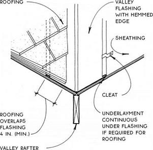
iN LOCATiONS WiTH SEVERE WEATHER, BiTUMiNOUS SHEET WATERPROOFiNG iS LAPPED OVER VALLEY FLASHiNG AT Both Sides FOR LENGTH OF
valley.
|
1-IN. cRIMp IN FLASHING IF ROOF
planes discharge unequal amounts
OF RAINWATER DuE TO
unequal pitches or unequal areas OF watershed.
Section A-A
Sidewall flashing is a single-piece flashing installed before the roofing to create a flashing channel against the wall (see 171B). This type of flashing is adequate for most situations and allows easy reroofing.
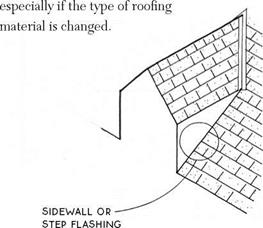
 Step flashing is a multiple-piece flashing that is woven in with the courses of roofing material (see 171C). This flashing is best for severe weather conditions. It may present some reroofing difficulties,
|
|
|
|
Posted by admin on 23/ 11/ 15
When J. D. was 51 years old he consulted Dr. Elliott complaining of insomnia, asthma, and fatigue. It became clear from an exhaustive environmental history that J. D.’s symptoms began during the time he lived downwind from a location where aerial spraying was carried out seasonally for pest control. The repeated pesticide exposures apparently had left the patient feeling debilitated, without his usual zest for life, and with multiple medical problems, including allergies and sensitivities to a wide range of substances.
As part of his treatment program, J. D. was advised to reduce his exposure to toxins in his home. Since he was on a limited budget owing to his decreased earning capacity, he concentrated his cleanup efforts primarily on the bedroom, intending to focus on the rest of the house later. Given the time he spent in bed, J. D. realized that his bed should be the healthiest place in the house. He had recently purchased a mattress made of artificial foam. The synthetic fibers were emitting formaldehyde fumes as the mattress aged, probably contributing to the tight feeling in his chest upon waking. Fortunately, J. D. was able to sell his boxspring mattress and purchase an organic cotton futon, which he placed in an untreated wooden frame. His formaldehyde impregnated, wrinkle-free sheets and polyester bedding were exchanged for 100 percent organic cotton pillows, sheets, and blankets. Because of his concern about possible dust mites in the mattress, he used an organic cotton barrier cloth, woven so tightly that it was impenetrable to these insects. He laundered his bedding frequently in unscented, nonchlorinated detergent.
After J. D. recovered financially from replacing his bedding, his next project was to pull up the old carpet in the bedroom. Although the carpet was several years old and no longer outgassed toxicfumes, it was still a reservoir for dust, dirt, and microorganisms in spite of frequent vacuuming. J. D. wanted a floor that was attractive, health enhancing, and easy to clean. He chose to install presealed cork flooring because it resembled wood yet felt soft to the bare foot. On the floor he placed two untreated wool scatter rugs that could be easily taken up and cleaned.
The heating system in J. D.’s house is forced
good support and absorbency in a chemical – free environment. Untreated wool will repel dust mites, mold, and mildew. The mattress base should be a European-style wood-slat foundation, which allows the natural mattress to breathe and gives the same height and look as a conventional box spring. People with sensitivities to natural latex would need to test a mattress with latex before making a costly purchase as most mattresses are nonreturnable.
Permanent-press bedding is treated with formaldehyde that remains in the fabric after washing. Wool blankets may be mothproofed with harmful chemicals. Even pure cottons, unless organically grown, are heavily sprayed with pesticides. Healthy choices for bed sheets include organic natural fibers in cotton, cotton flannel, silk, hemp, or linen. Blankets, duvets, and comforters are available in organic down, silk, wool, or cotton.
air. The ductwork had been cleaned on a regular basis and electrostatic air filters were used on the return air ducts. Nevertheless, J. D. decided to close off the vents to his bedroom and use an electric ceramic heater. In addition, for the bedroom he bought a portable air filter that contained a HEPA filter for dust, mold spores, and pollen and a charcoal filter for fumes. The electric motor in the air filter was sealed to avoid toxic emissions and the unit itself was housed in a metal box.
J. D. did not know whether he was sensitive to electromagnetic fields. Since there would be little time or expense involved, he decided to take the necessary measures to reduce EMFs. He discarded his electric blanket, replaced his digital alarm dock with a battery operated one, moved his telephone into an adjacent room, and plugged in his television at the other side of the bedroom so that the screen was more than eight feet from his head.
The curtains on the windows were replaced with naturally finished wooden louvers, which were handsome and easy to clean. The room was cleaned once a week with a simple solution of vinegar and water. He was careful not to introduce toxic odors such as air fresheners, fabric softeners, colognes, and other artificially scented household products. When he occasionally needed to dry- clean his clothes, he left them on the back porch for a few days to air out the toxic chemicals found in dry-cleaning fluid. He was careful to remove his shoes before entering his sanctuary.
J. D.’s efforts paid off. He noted a definite improvement in his overall health. He was now able to get a full night of uninterrupted sleep and awake feeling refreshed, without the tight sensation in his chest. His energy increased and he was able to think more clearly. J. D. gradually regained his enthusiasm for life and has become a great proponent of the benefits of bedroom sanctuaries.
Discussion
We spend an average of eight hours a day in our bedrooms. Sleep is an important time for rest and recovery for all of us, whether we are sick or in the best of health. Designing our bedrooms with special care can create a healing environment where our bodies can mend from the daily barrage of exposures we all experience to varying degrees.
There is some confusion about the various terms used to describe cotton products. According to the Pesticide Action Network, conventionally grown cotton accounts for nearly 25 percent of the worlds insecticide use. Organic cotton is grown without the use of synthetic pesticides or fertilizers and with farming practices that increase soil fertility. Natural or green cotton products use conventionally grown cotton but are free of harsh chemical bleaches, dyes, and sizing elements such as formaldehyde. “100% cotton” indicates that no other fibers have been used in the fabric but does not mean that the fabric is organic or naturally processed.
Sources for organic beds and bedding include:
• Casa Natura: Consultant and retail source for natural and organic beds, bedding, and linens
Posted by admin on 23/ 11/ 15
The safety provided by wearing course mixtures is of primary importance. The antispray properties of some mixes enhance safety by preventing the buildup of water mist behind vehicles. After rainfall (or melting snow), drops of water are raised up from a pavement by vehicle tires, especially the tires of large, fast-moving vehicles. Consequently, a certain amount of water in the form of mist remains suspended in the air surrounding fast-moving vehicles (Figure 12.7). Then it settles on windscreens, reducing visibility.
The generation of water mist and splash may be decreased by enabling quick water discharge after rainfall (through transverse cross-falls and having no ruts to hold water), a suitable depth of macrotexture, or a high content of air voids in a course. The last condition refers to open-graded friction course or porous asphalt. Water discharge through the whole thickness of a course is out of the question in the case of SMA. It is possible only through spaces among coarse aggregates sticking
|
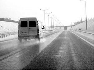
figure 12.7 Water mist picked up by vehicles driving along a wet SMA pavement is reduced. (Photo courtesy of Krzysztof Blazejowski.)
|
up from the surface of the course; hence, the proper SMA macrotexture is all important (Figure 12.8). Investigations conducted in the United States have proved that SMA courses reduce water splash in comparison with AC pavements; nevertheless, water remains longer on the SMA course where it can be held in the surface voids (Schmiedlin and Bischoff, 2002). The issues of SMA macrotexture were discussed in the Section 2.7 devoted to antiskidding properties.
Furthermore, macrotexture that reduces the water film on the surface of a wearing course is also of significance to the improvement in visibility of road marking after or during rainfall. Moreover, at night the light reflection (“glistening”) of vehicles travelling in the opposite direction is reduced. Figure 12.9 shows an image
|
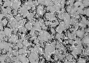
FIGURE 12.8 Water discharge through small channels around SMA coarse aggregates. (Photo courtesy of Krzysztof Blazejowski.)
|
|

FIGURE 12.9 Differences in pavement abilities to discharge water—the SMA course (near) and the old dense asphalt concrete (far). The light reflection off the wet SMA course is substantially less than that off the asphalt concrete course. (Photo courtesy of Krzysztof BlaZejowski.)
|
of wearing course surfaces made of SMA and AC after rainfall and their light reflections (during the daytime). The difference in the way water is discharged as a result of the surface macrotexture is clearly noticeable.
Posted by admin on 23/ 11/ 15
The transport model of pollutant leaching from the secondary road construction material was developed by the Environmental Research Group from the University of New Hampshire, USA (Apul et al., 2003). Water flow in a Minnesota highway embankment was modelled in one dimension for several rain events and calibrated to the field condition (Fig. 11.20). The test facility consists of 40 and 152m-long
|
Number of load cycles, N
Fig. 11.19 Comparison of maximum rut depths measured on the experimental pavement and predictions with ORNI (rutting of UGM and subgrade, different temperatures)
|
hot mix asphalt and Portland cement concrete test sections with varying structural designs. Each test section is instrumented to monitor strength and hydraulic properties. The hydraulic properties of the embankment were predicted from water content measurements made in the embankment, a Portland cement concrete pavement with an asphalt shoulder. The hypothetical leaching of Cadmium from coal fly ash was probabilistically simulated in a scenario where the top 0.50 m of the embankment was replaced by coal fly ash. The groundwater table was set at 1.9 m below ground level (b. g.l.), which is within the range (1.3-4.6m b. g.l.) observed at test site. An entire year’s precipitation data repeated 10 times was input as the variable flux boundary condition. The molecular diffusion coefficient of Cadmium in free water
|
Fig. 11.20 (a) Cross section of MnROAD test Section 12; (b) conceptual model of the MnROAD embankment (Apul et al., 2003). Reproduced by permission of ISCOWA
|
was input in the model as a constant (6.2 x 10⁻⁵ m2/day) and tortuosity factor was calculated within the finite element code, HYDRUS2D, as a function of the water content.
The probability distributions of unsaturated hydraulic properties of the embankment were determined from parameter posterior probabilities obtained from embankment infiltration simulations. The probability distributions were used to fit to the four parameters of the van Genuchten SWCC model (see Chapter 2, Section 2.7.3). Weighted moment equations were applied to calculate the means and standard deviations for the normal distributions. Saturated permeability and saturated water content were assigned joint log-normal distributions. To account for the variability of partition coefficient, kd, uniform distributions were assigned. In the study kd was considered as lumped parameter. The temporal and spatial variability of kd that would be expected in the field was incorporated in the modelling approach by probabilistically varying kd values of the subgrade and the coal fly ash for each simulation.
The average percentage of initial available mass leached after 10 years, as observed 0.01 m below ash, is presented, idealised, in Fig. 11.21, for a point a short way into the ash layer (point marked on Fig. 11.20). No significant Cadmium fluxes were observed 0.25 m below the coal fly ash or at the groundwater table depth. After 10 years, the fraction of initial available mass leached was 5 x 10⁻⁶ percent at 0.25 m below the coal fly ash, and 0% at the groundwater table depth (at the 90th percentile of uncertainty). The cumulative release at the 90th percentile of uncertainty and the appropriate probability distributions, was 2.65 x 10⁻³ mg Cd/kg ash after 10 years. The mean of the release estimate was 1.15 x 10⁻³ mg Cd/kg ash. Further details
|
Proportion of initially available mass leached
Fig. 11.21 Cumulative probabilities of percentages of initial available mass leached (as observed 0.01m below coal fly ash) after 1, 5 and 10 years. (Apul et al., 2005). Courtesy of D. Apul
|
are available from Apul et al. (2005) but it is clear that infinitesimal leaching occurs in real pavement/earthworks sections arranged in a similar way to the construction studied in Minnesota.
11.5 Conclusions
The partial differential equations that govern solid mechanics, water transfers, heat transfers and pollutant transfers have been restated. The specificities of the finite element method when dedicated to such non-linear phenomena and their coupling have been summarised. Then a number of numerical simulations have been presented. They cover moisture transfers, freezing, mechanical strains and permanent deformations. It appears that, for the most part, realistic numerical modelling is today available, at least for advanced research teams. But progress is still needed, for example to couple changes of moisture level and changes of the mechanical behaviour.
Posted by admin on 23/ 11/ 15
We had several conversations about the use of the new space, where the door and windows would go, and the like. We agreed that we wanted plenty of south-facing windows and that they would have to be of some opening style with a screen option. We found some excellent Caradco™ double-hung windows at a good price, but what really sold Jaki on them was that both the upper and lower sashes could be rotated 180 degrees for easy cleaning. After all, there would be no easy access to the windows exterior on the second story.
A nagging question was whether or not we would be able to maintain the same i:i2 roof slope in an upstairs addition and still have sufficient headroom. I checked this with my tape measure and found that there would be plenty of headroom, even at the southern end of the extended five-by-ten roof rafters. We proceeded to the design stage.
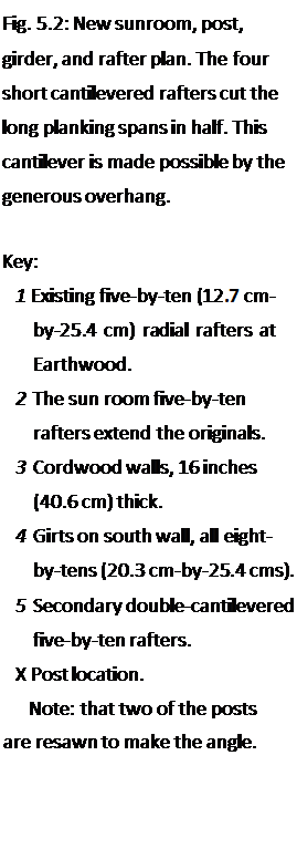
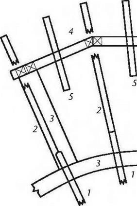
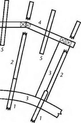
Before tearing the pressure-treated boards off, I used a black crayon to lay out the new room on the outside deck, a great aid in planning. We could visualize and mark all the components in their actual positions. Then, on paper, and using a scale of one-half-inch to the foot, I drew the post-and-beam support structure (Fig. 5.2), and a second plan at the same scale, this one for the replacement four – by-eight system which would serve as the floor support for the new addition. (Fig. 5.3). Note that the primary difference between the upstairs rafter plan and the downstairs ceiling joist plan (apart from timber dimensions) is the way the two different structures support the long planking spans which occur as the extended radial rafters get further apart.
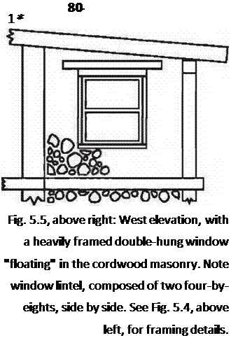
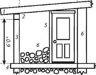
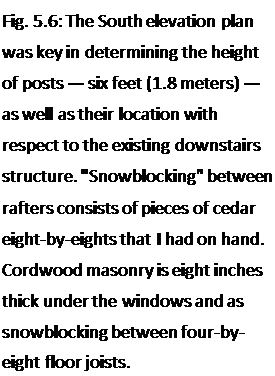
I also drew elevations of all three new sides of the new room, so that I could figure out the windows and door, as well as the post, height. Drawing the extended rafters in scale, and at the correct pitch, showed the post height, and these figures could be checked on site with actual measurements. (Figures 5.4, 5,5 and 5.6). I submitted my plans, along with the $15 fee, to the towns building inspector, and got a permit, an important step.
 The plans also made it easy to generate a materials list, which, in April, I brought to two sawmills for bid. We accepted the slightly higher bid because of quicker and more reliable delivery. This gave the timbers more drying time, and the decision seems to have been a good one, as we have not experienced egregious The plans also made it easy to generate a materials list, which, in April, I brought to two sawmills for bid. We accepted the slightly higher bid because of quicker and more reliable delivery. This gave the timbers more drying time, and the decision seems to have been a good one, as we have not experienced egregious
Fig. 5.3: The floor joists for the new room (which are also the ceiling joists for the old one) have four transverse headers to support one end of the short secondary joists. A self-supporting cantilever was not possible at this level in the way that it was for the roof
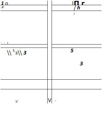   rafters. rafters.
Key:
1 Existing four-by-eight (Ю. І cm – by-20.3 mm) radial joists at Earthwood.
2 Eight-by-eight (20.3 cm-by-
20.3 cm) cedar girts newly installed at top of existing cordwood wall.
3 Replacement four-by-eight joists, married to house joists.
4 Secondary four-by-eight joists cut planking span in half.
5 Headers, all four-by-eights.
6 South wall girts or girders, all eight-by-tens (20.3 cm-by-25.4 cms).
7 Cordwood walls, 16 inches (40.6 cm) thick. Cordwood walls under south-facing windows (see Fig. 5.6) are 8 inches (20.3 cm) thick.
 |
|
Fig. 5.4: East elevation, with door.
Key:
1 Five-by-ten (12.7 cm-by-25.4 cm) rafter.
2 Eight-by-ten (20.3 m-by-25.4 cm) girt or girder.
3 Eight-by-eight (20.3 cm-by – 20.3 m) post.
4 Eight-by-eight cedar girt.
5 Four-by-eight (10.1 cm-by-20.3 cm) doorframe.
6 Typical cordwood masonry infilling.
|
|

E____ □____ D
Key:
1 Primary five-by-ten (12.7 cm-by-25.4 cm) rafters
2 Secondary (short) five-by-ten rafters
3 Eight-by-ten (20.3 cm-by-25.4 cm) girts
4 Eight by eight (20.3 cm-by-20.3 cm) posts, six feet long
5 Six-by-eight (15.2 cm-by-20.3 cm) posts, cut at an angle to make the bend in the south wall (See Fig. 5.2)
6 Eight-by-eight cedar girt
7 Existing lower story framework
8 Two-by-six (3.8 cm-by-14.0 cm) tongue-and-groove planking
9 Eight-by-eight beam pieces as snowblocking
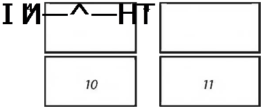
10 42-inch-wide by 48-inch-high (107cm by 122 cm) double-hung windows
11 46-inch-wide by 48-inch-high (117cm by 122cm) double-hung windows
wood shrinkage. The heavy timbers, as listed, cost about $760. This list is given as an example only. Adjustments were made, so it may or may not serve as an accurate materials list to build a similar sunroom. The “purpose” column matters little to the sawyer, but will be helpful to you when you try to figure out what all these pieces are for.
 The flooring and roofing two-by-six tongue-and-groove planks are not included. We needed about 850 board feet of these, which cost us $773. The flooring and roofing two-by-six tongue-and-groove planks are not included. We needed about 850 board feet of these, which cost us $773.
|
7
1
1
4
1
7
8
6
4
1
2
2
4
|
Timber Schedule for Earthwood Sunroom
(all white pine except as noted)
|
Dimensions
|
Length
|
|
5" x 10" (12.7×25.4 cm)
|
10′ (3 m)
|
|
8" x 10" (20.3×25.4 cm)
|
12′ (3.6 m)
|
|
8" x 10" (20.3×25.4 cm)
|
14′ (4.3 m)
|
|
8" x 8" (20.3×203 cm)
|
14′ (4.3 m)
|
|
6" x 8" (15.2 x 20.3 cm)
|
14′ (4.3 m)
|
|
4" x 8" (10.1 x 20.3 cm)
|
10′ (3 m)
|
|
4" x 8" (10.1 x 20.3 cm)
|
8′ (2.4 m)
|
|
1" x6" (2.5 x 15.2 cm)
|
8′ (2.4 m)
|
|
111 x 10" (2.5×25.4 cm)
|
12′ (3.6 m)
|
|
Iм x 12" (2.5×30.5 cm)
|
10′ (3 m)
|
|
2" x 8" (5.1 x 20.3 cm)
|
12′ (3.6 m)
|
|
(The following pieces shall 1
|
|
8" x 8" (20.3 x 20.3 cm)
|
10" (3 m)
|
|
2" x 8" (5.1 x 20.3 cm)
|
8" (2.4 m)
|
Purpose
Rafters (2 cut in half)
Main (center) south wall girt
Right and left south wall girts (cut into 2 @ 7′).
Posts (when cut in half)
Posts (when cut in half)
Floor joists (2 cut in half)
Doorframes (1 for lintel, 1 extra)
Cordwood key pieces and other Broaden lower story girders Finish interior of lower story posts South wall window framing n white cedar)
East and west downstairs wall girts West wall window framing
An eraser is one of your most valuable tools. Figure out the structure and jointing details on paper, ahead of time. Erasing and redrawing a few lines at the design stage can save major headaches later on. If you can’t visualize the situation from paper plans, build a scale model, a great way to figure out how things are connected. If you can’t build the model, maybe you shouldn’t try to build the real thing.
I have deliberately described the order of events we followed, because it is typical of any building project, large or small. It all starts with conceptualization of the project, which should involve all of the interested parties. This is followed by more detailed drawings, securing a building permit, and, finally, the pricing and procurement of materials. After all that is done…
| |


![K-out-of-ДО parallel systems Подпись: d [ps,sys(t)] dt M Y^CM,j [Ps(t)]j [1 j =K](/img/1312/image1124.png)




 NOTE
NOTE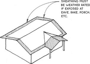


 most manufacturers specify a 1/8-in. space






 FELT uNDERLAYMENT LAPS OVER METAL EAVE FLASHiNG.





 Step flashing is a multiple-piece flashing that is woven in with the courses of roofing material (see 171C). This flashing is best for severe weather conditions. It may present some reroofing difficulties,


 The plans also made it easy to generate a materials list, which, in April, I brought to two sawmills for bid. We accepted the slightly higher bid because of quicker and more reliable delivery. This gave the timbers more drying time, and the decision seems to have been a good one, as we have not experienced egregious



 The flooring and roofing two-by-six tongue-and-groove planks are not included. We needed about 850 board feet of these, which cost us $773.