IMPACT PERFORMANCE CRITERIA

The following criteria are necessary to ensure satisfactory impact performance of

luminaire supports.

• Use only designs that have been approved as crashworthy by the FHWA.

• The FHWA has established upper limits on the support mass and height of luminaire supports. These limits are applicable even when the breakaway characteristics have proven acceptable by crash testing. The maximum acceptable support weight (mass) is 1000 lb (454 kg), and the maximum luminaire support height is 60 ft (18.3 m). These values are increased from the limits of 600 lb (272 kg) and 50 ft (15.2 m) cited a few years ago. Any further increases in these limits should be based on full-scale crash testing and an investigation of vehicle characteristics beyond those recommended in NCHRP Report 350 [13, 19].

• Breakaway devices are designed to operate by being subjected to horizontal forces (device placed in shear). The devices are designed for this to occur when impacted at a typical bumper height of about 20 in (510 mm). Locating luminaire supports where they will be impacted at a different height will result in forces directed parallel to the support and thereby loading the devices in tension and compression. This results in improper operation of the breakaway device and possibly severe impacts and injuries to vehicle occupants. Superelevation, slope rounding, offset side slopes, curves, curbs, vehicle departure angle, and speed can all influence the striking height of a typical bumper. Negative side slopes should be limited to 1:6 between the roadway and the luminaire to help ensure that errant vehicles strike the support at an acceptable height [13].

• Use a wiring system that allows all circuit components to be shielded from impact, preferably underground, and that ensures that all electrical energy potentially available at the pole foundation surface is limited by the current-limiting fuses. Conductors pro­tected only by a circuit breaker should be not be accessible in the pole base.

• The major cost of a luminaire assembly is the pole, foundation, and breakaway devices. Select luminaires for performance and for a design flexibility that allows more selection of pole locations to produce a lighting system with fewer potential hazards.

• As a general rule, a pole will fall in line with the path of an impacting vehicle. The mast arm usually rotates so that it is pointing away from the roadway when resting on the ground. Consideration, however, must be given to the fact that falling poles may endanger pedestrians and may pose a danger to other motorists.

• A maximum 4-in (100-mm) stub height must be maintained to prevent vehicle snagging. Quick-disconnect electrical circuitry should also be used to facilitate the breakaway mechanism, to reduce the hazard of electrical shock from exposed wiring after impact, and to ease repairs.

• Foundations should be properly sized for surrounding soil conditions. Foundations that move through the soil upon impact place the breakaway mechanisms in bending rather than shear, resulting in improper actuation.

• Curbs, regardless of their shape or height, will elevate an impacting vehicle. The rise in height begins approximately 18 in (460 mm) from the curb and can extend as far as 10 ft (3050 mm). When possible, therefore, luminaire supports should be placed 10 ft (3050 mm) from the curb. If this is not possible, then they should be located closer than 3 ft (610 mm) from the curb. Luminaire poles placed between 3 and 10 ft (610 and 3050 mm) behind curbs increase the chances of improper break­away operation.

• If a luminaire support is placed behind a barrier, it may not be necessary to provide a breakaway feature. In general, if the support is within the design deflection dis­tance of the barrier, then either the barrier should be stiffened or a breakaway pole support should be used.

• Some agencies place luminaire assemblies on top of concrete median barriers. High-angle impacts, or impacts by large trucks or buses, can cause a luminaire mounted on top of a barrier to be struck. Breakaway design is not recommended for this type of installation because of the risk that a downed pole might pose to oppos­ing traffic.

• If a luminaire support is to be placed on top of a concrete barrier, then the barrier must be adapted to fit the pole base. Concrete safety-shape types are typically designed with an approximately 6-in-wide (150-mm) top surface. Since luminaire bases are typically 8 to 12 in (200 to 305 mm) in width, it is necessary to either widen the barrier top to 12 in (305 mm), or flare the barrier in the area of the luminaire.

• Design alternatives should be investigated with the goal of reducing the number of luminaires used along a section of roadway. Higher mounting heights can signifi­cantly reduce the total number of supports needed. Tower or high mast lighting can be used to effectively illuminate major interchanges. This method reduces the num­ber of poles and locates the supports much farther from the roadway.

• It should be noted that some agencies are experiencing problems with the failure of aluminum T-bases due to environmental loads. It is believed that this kind of failure, such as shown in Fig. 7.79, is initially caused by minor impacts from mowing units and other maintenance equipment. This causes small cracks at the bottom flange of the T-base that grow under environmental loads. The result is eventual separation of the bottom flange from the T-base as in Fig. 7.80.

FIGURE 7.79 Failure of luminaire support without impact.

FIGURE 7.80 Separation of bottom flange from T-base.

HOW MANY TURNS?

How many turns does it take to operate a double-disk valve? it depends on the size of the valve. Refer to Figure 11.14 for the answers to how many turns

HOW MANY TURNS?

FIGURE 11.14 ■ The number of turns required to operate a double-disk valve.

HOW MANY TURNS?

FIGURE 11.15 ■ Number of turns required to operate a metal – seated sewerage valve.

HOW MANY TURNS?

it takes to operate a valve. If you want to know how many turns it takes to op­erate a metal-seated sewerage valve, look at Figure 11.15.

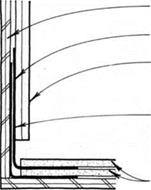
SIDEWALL FLASHING


WALL SHEATHiNG

FLASHiNG

FiNiSH WALL AND MOiSTURE BARRiER LAP FLASHiNG AT WALL.

KEEP SiDiNG NAiLS OUT OF FLASHiNG TO ALLOW VERTiCAL ADJUSTMENT WHEN REROOFiNG.


FLASHiNG ExTENDS 3 IN. (Min.) up WALL AND 4 IN. (Min.) ONTO ROOF.


FLASHiNG LApS 2 iN. (Min.) AT sidewalls


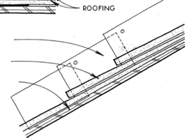
step

FLASHiNG (before IT is covered ву next course OF ROOFING)


NAIL NEAR TOp EDGE ABOVE pREViOuS FLASHiNG.

ROOF cOuRSES LAID OVER EAcH cOuRSE OF STEp FLASHiNG


FLASHiNG


ROOFING


SHEATHiNG


NOTES

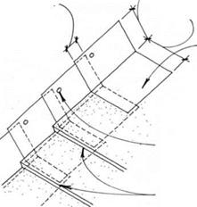
STEp-FLASHiNG piEcES ARE 2 IN. LONGER THAN ROOF cOuRSING exposure AND ARE INSTALLED WITH THE ROOFING MATERIAL, ONE cOuRSE AT A TIME. ExTERIOR WALL FiNiSH AND MOISTuRE BARRiER WILL LAp STEp FLASHiNG. FLASHiNG DIMENSIONS DEpEND ON ROOFING MATERIAL AND piTCH.


SIDEWALL FLASHINGSIDEWALL FLASHINGSIDEWALL FLASHINGSIDEWALL FLASHING

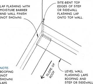
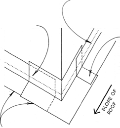
Подпись: BOTTOM EDGES OF FLASHINGS LAP ROOFING.Подпись: STEP OR SIDEWALL FLASHING LApS WALL FLASHING. Подпись: NOTE ROOFING (NOT SHOWN) LAPS SIDEWALL oR STEP FLASHING. SIDEWALL FLASHINGПодпись:Подпись: FLASHING.SIDEWALL FLASHING

LAP FLASHiNG WITH MOiSTURE BARRIER AND WALL FINISH (NOT SHOWN). –

LEVEL wALL

flashing, see 169D,

notched for step or

SIDEWALL FLASHING
vertical leg of step or sidewall

FLASHING ExTENDS

below corner, as allowed By

SIDING.

Lapped Flashing for Moderate Weather


Lapped Flashing for Moderate Weather


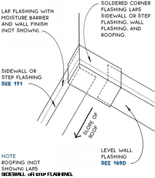
Подпись: SOLDERED CORNER FLASHING WRApS LEVEL WALL FLASHING. Подпись: LAP FLASHING WITH MOISTURE BARRIER AND WALL FINISH (Not SHoWN).SIDEWALL FLASHINGПодпись:

bottom EDGES of soldered corner flashing

AND LEVEL WALL FLASHING LAp

roofing.

SIDEWALL

of step

FLASHING

laps

soldered

corner

FLASHING.

note

roofing (not shown) laps

SIDEWALL oR STEp FLASHING AND

soldered corner

FLASHING.

Подпись: Soldered Flashing for Extreme WeatherSoldered Flashing for Extreme Weather

Подпись: Lapped Flashing for Moderate Weather

дЛ OUTSIDE CORNER FLASHING

INSIDE CORNER FLASHING

Lapped Flashing for Moderate Weather

Подпись:Подпись:SIDEWALL FLASHING

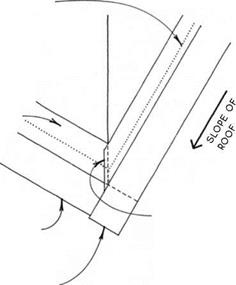
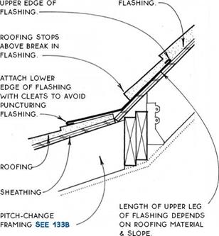
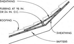
The flashing detail at left applies to both reduced pitch (shown) and increased pitch. Reduced pitch – change flashing can be avoided in favor of a cleaner detail by bending asphalt shingles or by soaking or steaming and bending wood shingles. The pitch change can also be made gradual by adding a strip of sheathing at the bend in the roof (see below) so that stiffer roofing materials such as wood shingles and shakes, tiles and slates can make the transition without flashing.

EXTRA

SIDEWALL FLASHING

PIPE THREADS

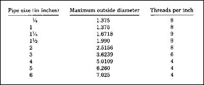
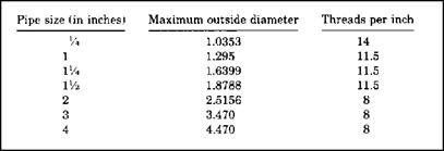
Pipe threads come in different styles. Some are compatible, and others are not. You could encounter straight pipe threads, tapered pipe threads, or fire­hose coupling straight threads. To understand the types of pipe and hose threads, let me give you some illustrations to consider. The tables in Figures 11.11, 11.12, and 11.13 show you how many threads per inch to expect with different thread types. Fire hose threads are not compatible with any other type of threads. The same is true for garden hose threads. But, some threads are compatible with other types. If you have a female NPT thread pattern, it is compatible with male threads of an NPT type. The proper sealant to mate these threads is a thread seal. American Standard Straight Pipe (NPSM) threads on female threads can be mated to either NPSM male threads or NPT male threads. To seal such a connection, a washer seal should be used.

PIPE THREADS

FIGURE 11.11 ■ Threads per inch for national standards.

PIPE THREADS

FIGURE 11.12 ■ Threads per inch for American Standard Straight Pipe.

PIPE THREADS

FIGURE 11.13 ■ Threads per inch for garden hose.

Female threads that are NPSH can be coupled with male threads of NPSH, NPSM, or NPT types. In any of these cases, a washer seal should be used. Threads of a garden hose type are mated with a washer seal. But, what happens when you are trying to find compatible matches for a male thread pattern? If you have an NPT male thread, it can be mated to NPT, NPSM, or NPSH threads. When NPT is mated to NPT, a thread sealant should be used. Washer seals are used to mate NPSM or NPSH female threads to male NPT threads. A male NPSM thread can mate with female thread types of NPSM or NPSH. A washer seal should be used for these connections. Garden hose threads, whether male or female, can only be coupled to garden hose threads, and this is done with a washer seal.

Methods for Computing Reliability of Complex Systems

Evaluation of the reliability of simple systems, as described in the preceding section, is generally straightforward. However, many practical hydrosystems engineering infrastructures, such as water distribution systems, have neither series nor parallel configuration. Evaluation of the reliability for such com­plex systems generally is difficult. For some systems, with their components arranged in a complex configuration, it is possible to combine components into groups in such a manner that it appears as in series or in parallel. For other systems, special techniques have to be developed that require a certain degree of insight and ingenuity from engineers. A great deal of work has been done on developing techniques for evaluating the reliability of complex systems. This section describes some of the potentially useful techniques for hydrosystems reliability evaluation.

7.4.1 State enumeration method

The state enumeration method lists all possible mutually exclusive states of the system components that define the state of the entire system. In general,
for a system containing M components, each of which can be classified into K operating states, there will be KM possible states for the entire system. For example, if the state of each of the M components is classified into failed and operating states, the system has 2M possible states.

Once all the possible system states are enumerated, the states that result in successful system operation are identified, and the probability of the occurrence of each successful state is computed. The last step is to sum all the successful state probabilities, which yields the system reliability. This method becomes less and less computationally attractive, as one can imagine, when the number of system components and/or the number of states for each component gets larger.

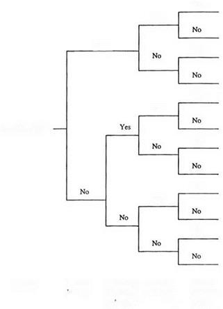
The tree diagram, such as that in Fig. 7.8, is called an event tree, and the analysis involving the construction of an event tree is referred to as event – tree analysis. As can be seen, an event tree simulates not only the topology of

Yes

Yes

Yes

Yes

Yes

Yes

Land flooded

Yes

Yes

Yes

Yes

Methods for Computing Reliability of Complex Systems

Sabotage Excess


Event


Methods for Computing Reliability of Complex Systems

Rood


(human, leakage


overtops


Methods for Computing Reliability of Complex Systems

Подпись: leveeanimal)

Figure 7.8 An example event tree for land flooding relating to levee performance.

a system but, more important, the sequential or chronologic operation of the system.

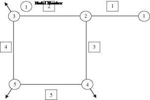
Example 7.12 Consider a simple water distribution network consisting of five pipes and one loop, as shown in Fig. 7.9. Node 1 is the source node, and nodes 3, 4, and 5 are demand nodes. The components of this network subject to possible failure are the five pipe sections. Within a given time period, each pipe section has an identical failure probability of 5 percent due to breakage or other causes that require it to be removed from service. The system reliability is defined as the probability that water can reach all three demand nodes from the source. Furthermore, it is assumed that the states of serviceability of each pipe are independent.

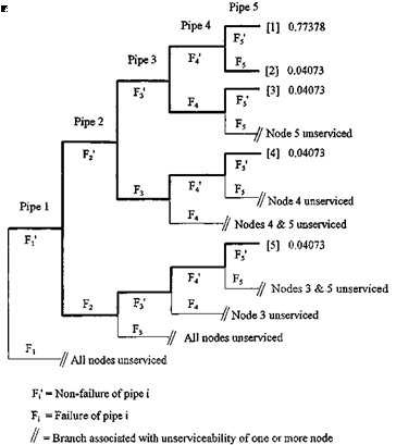
Solution Using the state enumeration method for system reliability evaluation, the associated event tree can be constructed to depict all possible combinations of com­ponent states in the system, as shown in Fig. 7.10. Since each pipe has two possible states, that is, failure F or nonfailure F’, the tree, if fully expanded, would have 25 = 32 branches. However, knowing the role that each pipe component plays in the network connectivity, exhaustive enumeration of all possible states is not necessary.

For example, referring to Fig. 7.10, one realizes that when pipe 1 fails, all demand nodes cannot receive water, indicating a system failure, regardless of the state of the remaining pipe sections. Therefore, branches in the event tree beyond this point do not have to be constructed. Applying some judgment in event-tree construction in this fashion generally can lead to a smaller tree. However, for a complex system, this may not be a trivial task.

Methods for Computing Reliability of Complex Systems

The system reliability can be obtained by summing up the probabilities associ­ated with all of the nonfailure branches. In this example, there are five branches, as

1 Pipe Number

indicated by the heavy lines in the tree, for which all users can have the water deliv­ered by the system. Therefore, the system reliability is

Подпись: = УУ P ( B[m])Подпись:Methods for Computing Reliability of Complex Systems
5

ps, sys = P ( и B[m] m=1

where P (B[m]) is the probability that the branch B[m] of the event tree provides full service to all users. The probability associated with each branch resulting in satisfactory delivery of water to all users can be calculated as the following:

P (B[1]) = P (F1) P (F2) P (F3) P (F4) P (F5)

= (0.95)(0.95)(0.95)(0.95)(0.95) = 0.77378 P (B[2]) = P (F1) P (F2) P (F3) P (F4) P (F5)

= (0.95)(0.95)(0.95)(0.95)(0.05) = 0.04073 P (B[3]) = P (F1) P (F2) P (F3) P (F4) P (F,5)

= (0.95X0.95X0.95X0.05X0.95) = 0.04073

P (B[4]) = P (F[) P (F2) P (F3) P (F4) P (F5)

= (0.95)(0.95)(0.05)(0.95)(0.95) = 0.04073 P (B[5]) = P (F1) P (F2) P (F<3) P (F4) P (F5)

= (0.95)(0.05)(0.95)(0.95)(0.95) = 0.04073

Therefore, the system reliability is the sum of the preceding five probabilities associ­ated with the operating state of the system, which is

ps, sys = 0.77378 + 4(0.04073) = 0.93668

Routine versus Demand Maintenance

Maintenance activities usually fall into one of two categories: demand or routine. Demand-responsive maintenance is response to random occurrences such as luminaire failures—i. e., lamps, fuses, ignitors, ballasts—or pole knockdowns. Routine mainte­nance is scheduled activities such as group lamp replacement or luminaire cleaning that are intended to produce a certain level of performance of the lighting system and eliminate some of the demand maintenance [18].

7.30.2 Maintenance Guidelines

A comprehensive discussion of roadway lighting maintenance is presented in “Design Guide for Roadway Lighting Maintenance,” IESNA DG-4. In addition to the factors affecting maintenance, this guide includes information for establishing a maintenance management system that will be helpful to agencies attempting to upgrade maintenance activities.

MAINTENANCE CONSIDERATIONS

Maintenance must be considered from the earliest design stages of a lighting project. Top-quality materials should be specified and then arranged or located to protect the components from the potential hazards of the environment, whether these be rain, mois­ture, ultraviolet degradation, or threat of vehicular impact. After a system is installed and tested for operation and for component integrity, proper maintenance procedures can produce continued high performance of the roadway lighting system. If the lighting system is not properly maintained, the responsible authorities may expose themselves to potential liability—plus increased costs if expendable items are not replaced as they reach the end of their service life, because they can cause other components to fail.

7.30.1 Maintenance Operations

There are many reasons to routinely maintain a lighting system. The first reason is that only through good maintenance can the system continue to perform as designed. No matter how much knowledge and skill goes into the design, and how much care is put into the installation inspections and final system testing, the system will not provide the performance expected of it if regular maintenance is not performed. In addition to the legal liabilities of a substandard lighting system, the condition of the system reflects the civic concern of the responsible agency. A lighting system containing faults such as burned out lamps, dirty luminaires, or knocked-down poles reflects a poor attitude that is very noticeable. Another factor is that the electrical energy costs are more or less constant even though the light on the roadways may be significantly reduced, so the economic efficiency is decreased.

Standby redundant systems

Подпись: Figure 7.7 Standby redundant systems.
Standby redundant systems

A standby redundant system is a parallel system in which only one compo­nent or subsystem is in operation (Fig. 7.7). It is a special case of K-out-of-M system with K = 1. If the operating component fails, then another component is operated. This type of system is different than the parallel system described in Sec. 7.3.2, where all components are concurrently operating because standby

Standby redundant systems Подпись: (7.61)

units do not operate. The system reliability for a system with M components out of which M — 1 units are on standby is the probability that at most M — 1 components fail. This probability can be expressed by

Подпись: MTTF = Подпись: 0 Подпись: Ps,sys(t) dt Подпись: 0 Standby redundant systems Подпись: (7.62)

Note that this equation is valid under the following assumptions: The switching arrangement is perfect, the units are identical, the component failure rates are constant, the standby units are as good as new, and the unit failures are sta­tistically independent. The mean time to failure of the system can be obtained, according to Eq. (5.18), as

Equation (7.62) is intuitively obvious in that the system’s operation is the result of a relay of a series of components. As one component fails, the second one comes to operation until failure occurs. Therefore, the system MTTF is the sum of the MTTFs of individual components.

Example 7.11 As an example of a standby redundant system, assume an exponential failure distribution for two identical pumps, one operating and the second on standby, with identical failure rates of X = 0.0005 failures/h. The standby unit is as good as new at time t = 0. The system reliability for t = 1000 h is

ps, sys(t = 1000) = [1 + (0.0005)(1000)]e—(00005)(1000) = 0.9098

Test Results

Figure 12.10 shows the results from tests of water permeability of an SMA mix­tures with gradations 0/4.75, 0/9.5, and 0/12.5 mm (Cooley and Brown, 2003). All instances concern U. S. SMA, previously described in Chapters 6 and 7.

Figure 12.10 clearly shows the relationship between the maximum aggregate size of the SMA and the probability of its being permeable. The larger the maximum aggregate size of the SMA, the higher the probability of its being permeable. Thus the size of the maximum particle is a decisive factor for permeability of an SMA

Подпись: 03 4 5 6 7 8 9 10 11 12 13 14 15 Air void content, % v/v FIGURE 12.10 Water permeability of SMA mixtures with gradation 0/4.75, 0/9.5, and 0/12.5 mm, depending on the size of the selected breakpoint sieve—the degree of gap gradation. (From Cooley, L.A. Jr. and Brown E.R., Potential of Using Stone Matrix Asphalt [SMA] For Thin Overlays. National Center for Asphalt Technology, Auburn University, NCAT Report 03-01, April 2003. With permission.)

mixture and so is the gradation within the coarse aggregate fraction (driven by the breakpoint sieve using the U. S. definition). An increase in this factor is followed by the growth of the size of internal pores, and consequently, the probability of their con­nection (Cooley and Brown, 2003). It has been stated in research (Cooley et al., 2002) that SMA mixtures are characterized by a higher potential for permeability than AC mixtures with the same content of air voids. Investigations of permeable pavements in Florida in the United States led to a definition of permeable mixtures as those mixtures with field permeabilities greater than 100 x 10-5 cm/sec[71] (Choubane et al., 1998). SMA mixtures may be prone to this excessive permeability, particularly those with a nominal maximum aggregate size greater than 10 mm.

ACCEPTANCE TESTS

Before any lighting system is accepted as complete, or preferably before the electricity is turned on, several tests should be conducted to ensure the quality of the components:

Insulation tests. The contractor should measure the conductor insulation resistance to ground of each lighting circuit using a 500-V megohm-range type instrument. A record should be made of each phase conductor’s resistance to ground. The circuits should measure a minimum of 250,000 Q resistance to ground before the power is turned on. The test should be arranged to test splices and all components of the circuit. Ground resistance test. Using an instrument designed for the purpose, the con­tractor should measure the resistance of each ground rod. A written record of the value should be signed and given to the inspector. Any ground rod with a resis­tance of 25 Q or less is acceptable. Additional ground rods, up to a maximum of three at each location, should be installed to reach the 25 Q.

High mast lowering test. Each high mast lighting assembly should be tested by completely raising and lowering the luminaire ring once. Further testing of the latching operation for top latch devices is necessary. Each luminaire ring should be unlatched, lowered a minimum of 6 ft (2 m), then raised and relatched a total of five times to demonstrate its acceptability.

Photocontroller test. The control circuit of the lighting system should be demon­strated to show it operates properly in both manual and automatic modes. The

Voltage tests. The supply voltage at the lighting control center should be measured and recorded. With the luminaires energized and at full brightness, the voltage at the last luminaire of the circuit should be measured to ensure no more than a 10 percent voltage drop is present.