PITCH-CHANGE FLASHING

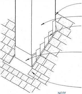
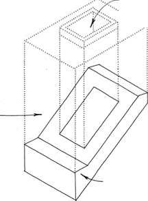
Подпись:PITCH-CHANGE FLASHINGwall sheathing on framing of wood flue

STEp FLASHiNG WOVEN WITH ROOFiNG COuRSES

(shown before it is lapped with moisture barrier & SIDING), SEE 171C,

OR

ALTERNATIVE SIDEWALL FLASHiNG, SEE 171B.

BASE FLASHiNG WRApS CORNERS, ExTENDS uNDER SHINGLES AT SIDES 4 IN. (MIN.) & LApS SHINGLES AT BASE 4 IN. (MIN.)

OR

ALTERNATIVE OuTSIDE CORNER FLASHiNG AT BOTH CORNERS, SEE 172A,

COMBINED WITH ABuTTiNG ROOF FLASHiNG,

SEE 169D.

Подпись: ROOFiNG LApS BASE FLASHiNG 4 IN. (MIN.) THIS FLASHiNG IS ALSO AppLICABLE FOR ANY WOOD-FRAMED pROTRuSiON THROuGH THE ROOF SuCH AS DORMERS, SEE 135 & 149B, OR SKYLIGHTS, SEE 175-176.
Подпись: NOTE FOR CLARiTY, WALL FiNiSH iS NOT SHOWN.

CHIMNEY FLASHING

Wood-Framed Flue

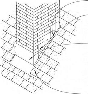
The flashing for a masonry chimney is best made of permanent materials such as copper or stainless steel. The flashing fits to the roof using the same principles as flashing for wood-framed flues (see 173B). The top edge of this flashing is then lapped with a counterflashing that is set into the mortar joints between masonry units. Because of the com­plex shapes, many of the pieces in chimney flashing cannot be folded but must be soldered or welded.

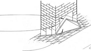
Подпись: STEP FLASHiNG WOVEN WiTH ROOFiNG COURSES SEE 171C COUNTERFLASHiNG SET iN MORTAR 1 iN. (MiN.) AT TOP EDGE, LAPS ITSELF 2 IN. (MIN.) & LAPS STEP OR OTHER SIDE OF FLASHING 4 IN. (MIN.). SOLDERED BASE FLASHiNG WRAPS CORNERS, IS SET IN MORTAR 2 IN. (MiN.) AT TOP EDGE, EXTENDS UNDER SHINGLES AT SIDES 4 IN. (MiN.) AND LAPS SHINGLES AT BASE 4 IN. (MiN.). THIS CAN ALSO BE MADE WiTH TWO piECES-A BASE FLASHiNG WiTH COUNTERFLASHiNG SET IN MORTAR. ROOFiNG LApS BASE FLASHiNG 4 IN. (MIN.). Подпись: Side & BasePITCH-CHANGE FLASHINGA chimney located in the slope of the roof will require a cricket (also called a saddle), a ridged connection

between chimney and roof that directs water

Подпись: COUNTERFLASHING SET IN MORTAR & CUT TO SLOpE OF CRICKETПодпись: SOLDERED COUNTERFLASHiNG CONTINUOUS AROUND CORNER LApS CRICKET.Подпись: STEP FLASHING (NOT VISIBLE) WOVEN WiTH ROOFiNG COURSES. SEE 171CПодпись: Side & CricketPITCH-CHANGE FLASHINGaway from the chimney. Most crickets may be formed with exterior-grade plywood; larger crickets may need to be framed like a typical roof. The entire surface of the cricket is flashed, as shown in the drawing below.

Подпись: FLUEПодпись: CHIMNEYПодпись: FLASHiNGПодпись: Through-Pan FlashingPITCH-CHANGE FLASHINGSOLDERED CRICKET WRApS CORNERS, EXTENDS UNDER ROOFiNG 6 IN. (MiN.) AND TURNS Up AGAINST CHIMNEY 4 IN. (MIN.).

In severe climates, a through-pan flashing that extends continuously through the chimney should be considered. Through-pan flashing prevents water from migrating through the masonry to a level below the flashing. It is made of lead or copper and is pen­etrated only by the flue. It is wrapped down at the edges, where it acts as counterflashing. The continuous flashing through the chimney does weaken the masonry bond, so this flashing should not be used in earthquake or hurricane zones.

PITCH-CHANGE FLASHINGPITCH-CHANGE FLASHING

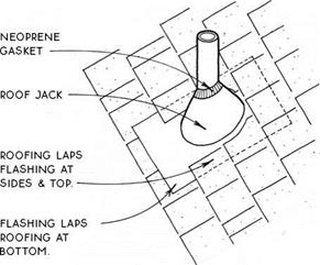
Modern roof jacks are typically fitted with neoprene gaskets sized to seal plumbing vents and other roof penetrations. Jacks are woven in with roofing mate­rials where possible. Jacks for metal roofs pose special problems.

MANAGING A FRAMING TEAM

This chapter is intended for advanced framers who are becoming “lead framers," or starting to manage a framing crew. Keep in mind that the lead framer’s productivity is defined by the productivity of the crew. If you’re taking on the job of lead framer, you’ll need to think about the information your crew needs and how to teach and manage them most effectively. Earlier chapters in this book will help you train your crew in the specific steps of various framing tasks. But there are other aspects to managing a crew. It’s the lead framer’s job to get the building framed on time and within budget. The lead framer must also be sure that the expected quality standards are met, and that the building is structurally sound, visually aligned, and ready for inspectors and for other trades—all of this while maintaining a safe and congenial workplace. To meet all of these goals is an impressive accomplishment. The purpose of this chapter is to help you get there.

Management techniques have been developed over the years by studying and applying methods that work. The trend has been away from the dominating “command" approach and toward the cooperative “team" approach. This chapter deals with some organizational tasks, as well as with relationships and motivation. Developing good working relationships and instilling motivation is probably the most important and the most difficult task of a leader. A construction project manned by crews of skilled craftsmen who take pride in their work and get along with each other is bound to be successful. Assembling and directing such crews can only be accomplished by a leader who has developed good management skills.

Managing a framing team is a task like no other.

The job changes every day and is always full of new surprises. The lead framer should be good at multi-tasking. A typical day might include trying to make sense of plans that don’t provide enough information, dealing with an owner or general contractor who is focused more on cost and schedule than the details of framing, and organizing a group of framers who have different levels of knowledge and experience into an effective team.

The most valuable tools you can have in managing a crew are common sense, framing knowledge, the ability to evaluate a situation objectively, and an understanding of your crew’s abilities and personalities. You probably already have a preferred management style, based on what you have learned in your experience in the field. This chapter will help you better understand that management style and improve upon it.

INSTALLING J-CHANNEL AROUND WINDOWS

INSTALLING J-CHANNEL AROUND WINDOWSHelping Hand

Dispose of waste drywall. Before you send waste dry – wall to a landfill, contact the Gypsum Assoriation (see Resources on p. 278) to see whether there’s a recycling facility in your area. Local builders may also know of recycling possibilities that can help reduce the amount of construction material sent to landfills.

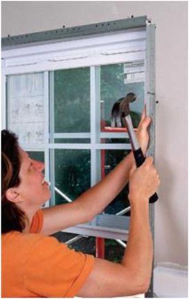
Using J-channet around a window makes a dean joint between the drywall and the window frame.

INSTALLING J-CHANNEL AROUND WINDOWSПодпись:

corner beads are designed to be nailed or stapled in place. Use tinsnips to cut floor-to – ceiling beads. Cut them at least Zi in. short, but hold them tightly against the ceiling. Starting at the top and working down, fasten the bead to the corner stud (below the top plates) with pairs of nails or screws opposite each other every 8 in. to 10 in. A pneumatic stapler also works well. Make sure all the beads are straight and lie flat against the wall.

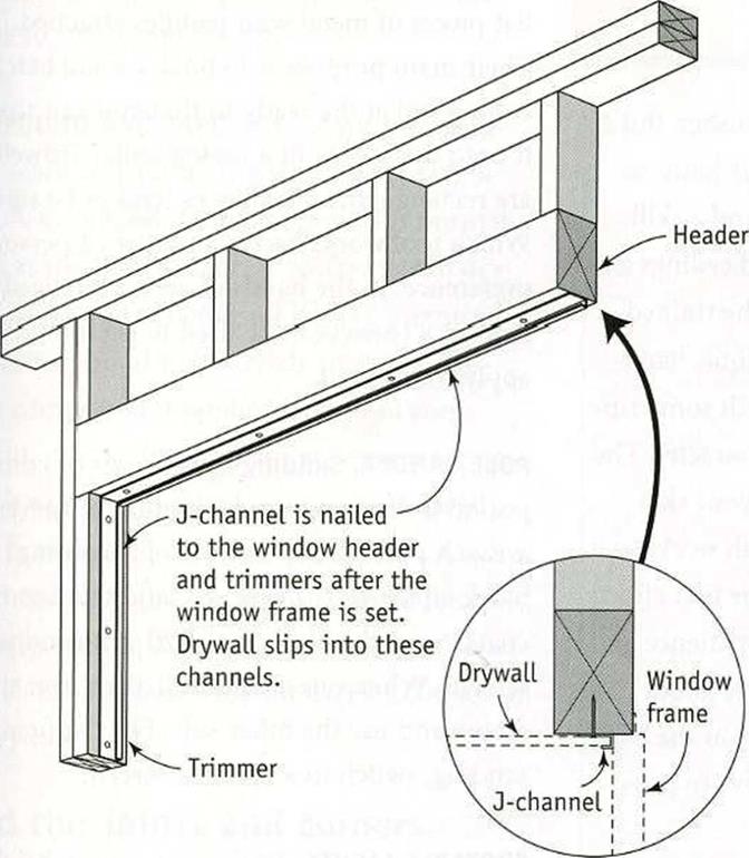
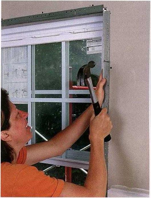
Beads around windows and doors are attached just like those on corners. The header beads are cut square on both ends and then nailed in place. The side trimmer pieces are also cut square and butt into the top piece (see the photo at right).

Подпись: Helping HandПодпись: Reuse joint compound buckets. These rugged, plastic buckets are great for storing tools and materials. Wash out any remaining joint compound with water.STEPS Mud, Tape, and Finish the Drywali

I am not a professional drywali finisher. But I have taped enough wall and corner joints to know that this job is both an art and a skill. Some finishers can leave walls and ceilings as straight and smooth as glass. To the trained eye, my work looks more like antique, hand­made glass—generally flat, but with some rip­pling and variations that give it character. The thing to remember, regardless of your skill level, is that taping drywali is finish work, so it needs to look good. Although your first efforts aren’t likely to be masterful, with patience and know-how you can learn to achieve good, solid work. This section will give you the basic know-how. The patience you111 have to pro­vide yourself.

Tool up for finishing drywali

Although professional drywali finishers rely on an assortment of equipment, including stilts to speed ceiling work, you can achieve very good results with just a few tools. You’ll find them at well-stocked hardware stores, home centers, and drywali-supply outlets.

TAPING KNIVES. Mud applicators are called knives, even though they look more like over­grown spatulas. A 5-in.-wide knife is good for applying joint compound (referred to as mud). Wider knives are used to smooth and feather the edges of mud, tapering it so thin that it will be as undetectable as possible once the paint is applied. If you’re new to drywali work, start with 5-in., 8-in., and 12-in. knives for best results.

TROWELS AND HAWKS. These tools are simply flat pieces of metal with handles attached. Their main purpose is to hold a small batch of compound at the ready so that you can scoop it onto the wall with a taping knife. Trowels are rectangular, while hawks tend to be square. Which tool works best is a matter of personal preference. In the hands of an experienced worker, a trowel can be used to both hold and apply compound.

POLE SANDER. Sanding finish coats of com­pound is often necessary to smooth uneven areas. A pole sander consists of a sanding block attached to a pole. To sand the first two coats, cover the block with 120-grit sanding screens. When one side is dull, turn over the screen and use the other side. For the final sanding, switch to a 150-grit screen.

PORTABLE LIGHTS. With one or more bright, halogen-type work lights, you’ll have a much easier time finding flaws in the top coat.

DUST MASK AND GOGGLES. Don’t begin to sand drywali compound without donning safety gear.

Do the prep work

Before you start taping and mudding, make sure that all fasteners are below the surface of the drywali. You can do this by running your hand or a wide drywali knife over the fasten­ers in the walls and ceiling. If any fasteners are proud of the surface, they will show when you apply the first coat of mud.

You may need to do a bit of repair work around electrical-outlet boxes. If the fit around these boxes is sloppy, use a fast-setting (as opposed to a slow-drying) joint com­pound that’s available at supply stores. Mix a batch and fill the gaps with a small putty

knife. If the gaps are quite narrow, use latex caulk to seal around them.

COMPOUND AND TAPE. Part of your prepara­tion work is making sure you have the right supplies on hand. Joint compound is normally used as the bed for tape. If you’re new to dry – wall work, you’re better off buying premixed joint compound that is ready to apply. Top­ping compound is applied over joint com­pound; it has a finer, creamier consistency so that it can be smoothed out nicely. It’s avail­able in premixed and powdered forms. You’ll also need enough tape to cover all the joints between panels, including the inside corners. Buy about 400 ft. of tape for every 1,000 sq. ft. of drywall.

Mud the joints and corners

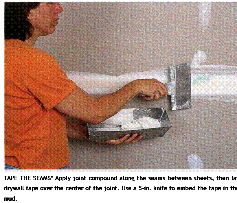
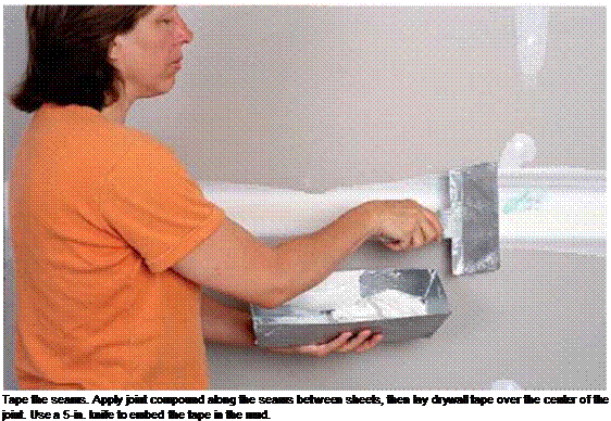
The long edges of drywall panels are tapered, allowing the seams between adjacent panels to be filled with joint compound and taped to create a level surface. Begin by using a 5-in. knife to apply mud about % in. thick along the entire seam. Roll out the tape from corner to corner, center it on the joint, press it lightly in place, and then pull it tight and straight.

Once the tape is in place, drag the knife over the top, applying enough pressure to embed the tape as you go (see the photo at left on p. 230). Make sure the tape is flat, wrinkle- free, and embedded in about % in. of mud. Be careful not to create mud buildup in the cor­ners. Clean any excess compound from along the edges of the tape with your knife.

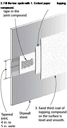
Подпись: TAPING AND MUDDING JOINTS 2. Fill the low spots with Подпись: 1. Embed paper topping compound. Tape and drywall compound hide the joints and make them strong. INSTALLING J-CHANNEL AROUND WINDOWSПодпись:Inside corners and wall-ceiling joints are taped a bit differently than flat joints in a ceil­ing or wall. Use a 4-in. or 5-in. knife to apply an S^-in.-thick layer of joint compound on each edge of the corner. Next, fold the tape at the crease and press it into the corner, flatten-

Подпись:

ing it as you go. Working on one edge at a time, press the tape against the drywall and into the mud with the taping knife.

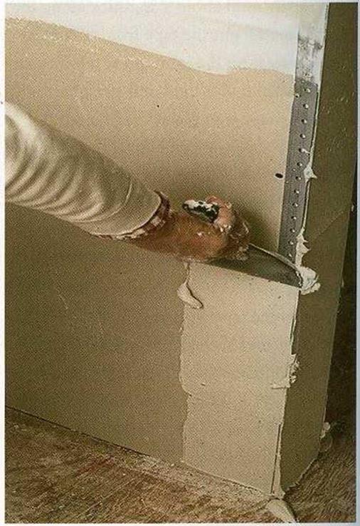
Outside corners covered with corner bead are easier to do (see the photo at right below). Using the same 4-in. or 5-in. knife, press mud along the length of the corner. The outside edge of the comer bead acts as a guide for your knife as you pull off excess mud.

The ends of a drywall sheet are not tapered like the edges are. For this reason, you should use less mud to cover the tape at the butt joints, where the ends of adjoining sheets meet. Otherwise, you can create an obvious bump in the wall. Cover the tape lightly with mud, and feather the edges away from the

MUD THE CORNER BEADS. Apply joint compound generously along each side of a corner bead. To level off the compound, run the taping knife over the rounded outside edge of the bead. [Photo by Charles Miller, courtesy Fine Homebuilding magazine, ® The Taunton Press, Inc.]
center of the joint so any bumps that result will be slight.

In hot, dry climates, joint-compound applications dry rapidly. Mud that dries too fast may not bond well and can crack. Try mudding a couple of joints in a room and then applying tape right away, rather than mudding every joint first. You may need to close up the house to retain moisture and cre­ate a slower drying time. You can also use an easy-to-sand setting compound that hardens with little shrinkage and is basically unaffected by hot, dry conditions.

Its a different story in cold and humid areas. Builders in those regions often have to close up the house, turn up the heat, and open the windows a bit to let out moisture. Portable propane heaters work well to help things dry, but they exhaust additional moisture into the air. If you’re using them, leave a window open so moist air can escape. Kerosene heaters also work well, but it may take a while for the smell to leave the house.

INSTALLING J-CHANNEL AROUND WINDOWS

RETAINING WALLS

A. J. Siccardi, PE.

Formerly, Staff Bridge Engineer
Colorado Department of Transportation
Denver, Colorado

S. C. (Trever) Wang, Ph. D., P. E.

Senior Engineer

Colorado Department of Transportation
Denver, Colorado

Retaining walls are an important element in highway construction. They are most fre­quently constructed in the highway environment to retain a mass of earth. They are also used to enable the highway designer to establish grade lines for roadways at dif­fering elevations when such roadways are in close proximity to one another and are to be constructed within limited rights-of-way, as is generally the case in densely populated urban locations.

Until 1972, when the first Reinforced Earth wall in the United States was built in California, retaining walls utilized in highway construction were usually plain gravity or reinforced concrete walls. Now, the use of mechanically stabilized earth (MSE) walls has become widespread in construction throughout the United States. Because early walls included metal strap reinforcement as the primary mechanism for stabilizing the soil, corrosion of the reinforcement and lack of long-term durability were a major impediment to immediate acceptance. Currently, the utilization of metal reinforcing requires the addition of sacrificial galvanizing materials selected to ensure the design life of the structure.

More recent earth reinforcement systems utilize geosynthetic materials, which are deemed inert to attack by deicing salts used on the highways. Salts are a primary inducer of corrosion in metal reinforcement. Long-term creep characteristics of geosynthetic reinforcements, however, must be carefully considered. There are also increasingly more specialty-type walls, such as the soil nail type for both temporary and permanent wall locations, especially for slope stabilization where slope materials are appropriate for nailing. Each of these wall types is discussed briefly in this chapter.

The material in this chapter is drawn from many sources, including personal experi­ence, but primarily from the following sources: (1) Section 5, “Retaining Walls,” American Association of State Highway and Transportation Officials (AASHTO), Standard Specifications for Highway Bridges, 17th ed., 2002; and (2) Subsection 5 of the

Colorado Bridge Design Manual, “Earth Retaining Wall Design Requirements,” Colorado Department of Transportation. A list of references is given at the end of the chapter.

Retaining walls can also be designed by the Load and Resistance Factor Design (LRFD) method as given by AASHTO in LRFD Bridge Design Specifications. This is a method of proportioning structural elements by applying factors to both the loads (load factors) and the nominal strengths (resistance factors). The specified factors are based on the mathematical theory of reliability and a statistical knowledge of load and material characteristics. The load factors are multipliers (typically greater than 1.0) that take account of the variability of different types of loads, such as earth loads and live loads. Resistance factors (typically 1.0 or lower) account for inaccuracies in theory and variation of properties. Although AASHTO’s goal is to use LRFD for all new construction, the traditional methods are currently the choice of most retaining wall designers and, hence, are the focus of this chapter.

Apply the second and third coats

Drywall compound must be applied in sev­eral thin coats because thick applications tend to shrink and crack. Also, thin coats can be feathered or tapered very gradually so that they’re invisible (or nearly so) after the drywall surface is painted. Before applying the second coat, remove any lumps, high spots, or ridges of hardened compound left from the first coat. This can be done with a drywall knife or a pole sander. Be careful not to oversand, or you could damage the paper face of the drywall.

Apply topping compound over the dimples around the fasteners, just as you did with the first coat. Be even more careful as you level the compound, and use a 10-in. or 12-in. knife. Along seams, apply topping compound with a 5-in. knife, then use a 12-in. knife to remove the excess (see the top photo on p. 229). Again, take your time. The second coat should conceal the tape. Using a wider knife, feather the mud away from the center of the joints to make them harder to detect. This is especially important
at butt joints. It takes some practice to get this coat right. Go over the joints more than once, if necessary, pulling the knife with a steady, even pressure to leave a smooth surface.

The same can be done along inside corners, using a 5-in. knife to mud and smooth one side of the corner at a time. This takes some skill, because it’s difficult to keep the knife from marking the finished side as you mud the op­posite side. For this reason, some tapers like to use a different procedure. They apply mud on one edge at a time, smooth it, and then let it dry. Once one side of the corner is dry, they return and do the other side.

Before applying the third coat of compound, lightly sand the second coat. Hit the corners, dimples, and seams with a 120-grit screen on a sanding pole to remove any bumps, trowel marks, or ridges. The third coat should be little more than a light application of topping compound to hide any imperfections and feather the seams a bit wider. To make the topping compound easier to manipulate, thin it with a little water.

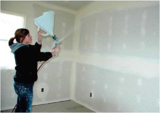
Apply the second and third coatsThe drywall in many houses, especially in the West and Southwest, is textured by using air to blow on a solution of drywall mud. [Photo by Don Charles Blom]

Pollution Mitigation

Mihael Brencic% Andrew Dawson, Lennart Folkeson, Denis Francois and Teresa Leitao

Abstract There is often a risk of pollution entering or moving in the road environ­ment. This may give rise to problems of various severities dependant on the local environment around and under the pavement. Therefore the risks have, first, to be assessed and then appropriate action taken to minimise the movements and/or the impacts. This chapter describes the criteria to be applied when considering pollution mitigation schemes and the constraints that must be taken into account. Both traffic considerations (which often form the driver for pollution supply) and economic con­siderations are included in the coverage of the chapter together with some comments on site sensitivity. In particular, the chapter provides a framework for considering alternative mitigation strategies against a background of the benefits and limitations of each. Pollution mitigation measures are only mentioned where they are identifi – ably different from conventional drainage measures which are covered more fully in Chapter 13.

Keywords Pollution control ■ impact mitigation ■ flow disruption ■ site sensitivity

12.1 Introduction

Roads and road traffic can act as serious sources ofvarious types ofpollution. Pollu­tants spread to the environment through different pathways, with different transport agents and mechanisms. Once pollutants are transported away from the road and traffic sources they can reach various environmental compartments where they can have detrimental effects. Pollution from roads and traffic must be managed and its harmful affects prevented at all stages, especially in environmentally sensitive areas.

The objective of this chapter is to describe general principles of prevention and mitigation of pollution that originate from road and traffic operation and that can influence the water environment. Consideration was taken mainly of mitigation of [27] deleterious effects caused by seepage water. Pollution prevention and mitigation is associated with several constraints that can be classified in five major groups; site sensitivity and vulnerability, risk and hazard to pollution, traffic characteristics, economic and legislation constraints.

In the second part of the chapter general principles of mitigation methods are described. A new classification of mitigation approaches based on the pollutant fate model that consist of the chain sources – pathways – targets is described. Classifi­cation is described based on the ex-situ and in-situ mitigation methods and descrip­tions of intervention and non-intervention mitigation measures are also introduced.

The content of this chapter is very much connected with the next chapter “Rec­ommendation for the control of pavement water” where design and technical mea­sures for pollution prevention are described.

Path enumeration method

This is a very powerful method for system reliability evaluation. A path is defined as a set of components or modes of operation that leads to a certain outcome of the system. In system reliability analysis, the system outcomes of interest are those of failed state or operational state. A minimum path is one in which no component is traversed more than once in going along the path. Under this methodologic category, tie-set analysis and cut-set analysis are two well-known techniques.

Cut-set analysis. The cut set is defined as a set of system components or modes of operation that, when failed, cause the failure of the system. Cut-set analysis is powerful for evaluating system reliability for two reasons: (1) It can be pro­grammed easily on digital computers for fast and efficient solutions of any general system configuration, especially in the form of a network, and (2) the cut sets are directly related to the modes of system failure and therefore iden­tify the distinct and discrete ways in which a system may fail. For example, in a water distribution system, a cut set will be the set of system components including pipe sections, pumps, storage facilities, etc. that, when failed jointly, would disrupt the service to certain users.

Подпись: pf ,sys — P ( U Cm 1 — P m=1 Подпись: I U m=1 Path enumeration method Подпись: (7.63)

The cut-set method uses the minimum cut sets for calculating the system failure probability. The minimum cut set is a set of system components that, when all failed, causes failure of the system but when any one component of the set does not fail does not cause system failure. A minimum cut set implies that all components of the cut set must be in the failure state to cause system failure. Therefore, the components or modes of operation involved in the minimum cut set are effectively connected in parallel, and each minimum cut set is connected in series. Consequently, the failure probability of a system can be expressed as

in which Cm is the mth of the total I minimum cut sets, Jm is the total number of components or modes of operation in the mth minimum cut set, and Fmj represents the failure event associated with the j th components or mode of operation in the mth minimum cut set. In the case that the number of minimum

cut sets I is large, computing the bounds for probability of a union described in Sec. 7.2.3 can be applied. The bounds on the failure probability of the system should be examined for their closeness to ensure that adequate accuracy is obtained.

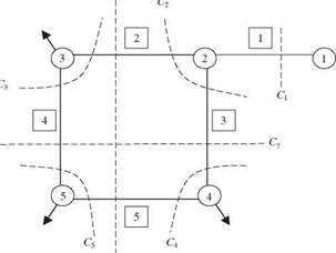
Example 7.13 Refer to the simple water distribution network shown in Fig. 7.9 in Example 7.12. Evaluate the system reliability using the minimum cut-set method.

Solution Based on the system reliability as defined, the minimum cut sets for the example pipe network are

C1 : F1 C2 : F2 П F3 C3 : F2 П F4 C4 : F3 П F5

C5 : F4 П F5 C6 : F2 П F5 C7 : F3 П F4

where Cm is the mth cut set, and Fk is the failure state of pipe link k. The seven cut sets for the example network listed above are shown in Fig. 7.11. The system unreliability pf, sys is the probability of occurrence of the union of the cut set, that is,

Pf, sys = P U Cm

m=1

The system reliability can be obtained by subtracting pf, sys from 1. However, the computation, in general, will be very cumbersome for finding the probability of the

C6

Path enumeration method


Nodal number


Pipe number


Path enumeration methodPath enumeration method

Cm = The mth cut set

union of large numbers of events, even if they are independent. In this circumstance, it is computationally easier to compute the system reliability as

Ps, sys = 1 — P ( U Cmj = P ( n Cm m=1 J m=1

Since all the cut sets behave independently, all their complements also behave in­dependently. The probability of the intersection of a number of independent events, according to Eq. (2.5), is

Подпись: m=1ps, sys = p( n C’r^j = ^ P(C’m) m=1 /

Подпись: whereP (C1) = 0.95 P (C2) = P (C3) = ••• = P (C’7) = 0.9975

Hence the system reliability of the example water distribution network is ps, sys = (0.95)(0.9975)6 = 0.9360

Path enumeration method Path enumeration method Подпись: mj Подпись: (7.64)

Tie-set analysis. As the complement of a cut set, a tie set is a minimal path of the system in which system components or modes of operation are arranged in series. Consequently, a tie set fails if any of its components or modes of operation fail. All tie sets are effectively connected in parallel; that is, the system will be in the operating state if any of its tie sets are functioning. Therefore, the system reliability can be expressed as

in which T m is the mth tie set of all I tie sets, Jm is the total number of compo­nents or modes of operation in the mth tie set, and F’mj represents the nonfailure state of the j th component in the mth tie set. Again, when the number of tie sets is large, computation of exact system reliability by Eq. (7.64) could be cum­bersome. In such a condition, bounds for system reliability could be computed.

The main disadvantage of the tie-set method is that failure modes are not directly identified. Direct identification of failure modes is sometimes essential if a limited amount of a resource is available to focus on a few dominant failure modes.

Example 7.14 Refer to the simple water distribution network as shown in Fig. 7.9. Use tie-set analysis to evaluate the system reliability.

Solution The minimum tie sets (or path), based on the definition of system reliability given previously, for the example network are

T1 : F1 n F2 n F’4 n F5 T 2 : F1 n F3 n F4 n F5 T 3 : F1 n F2 n F3 n F4 T 4 : F1 n F2 n F3 n F5

where T m is the mth minimum tie set, and F j is the nonfailure of the j th pipe link in the network. The four minimum tie sets are shown in Fig. 7.12. The system reliability, based on Eq. (7.64), is

Ps, sys — P(T 1 U T2 U T3 U T4)

= [P(T1) + P(T2) + P(T3) + P(T4)] – [P(T1, T2) + P(T1, T3)

+ P(T1, T4) + P(T2, T3) + P(T2, T4) + P(T3, T4)]

+ [P(T1, T2, T3) + P(T1, T2, T4) + P(T1, T3, T4) + P(T2, T3, T4)] – P(T1, T2, T3, T4)

Since all pipes in the network behave independently, all minimum tie sets behave independently. In such circumstances, the probability of the joint occurrence of multi­ple independent events is simply equal to the multiplication of the probability of the individual events. That is,

P (T1) — P (F1) P (F2) P (F4) P (F,5) — (0.95)4 — 0.81451

Подпись: —©

Path enumeration method Подпись: <D

Ъ————© ъ

и

Подпись: Яи

T4 = F1 п F 2 n F 3 п F 5

lm = The mth tie set

FJ = Nonfailure state of pipe section j

Similarly,

P (T 2) = P (T 3) = P (T 4) = 0.81451

Note that in this example the unions of more than two minimum tie sets are the intersections of the nonfailure state of all five pipe sections. For example, T1 U T 2 =

(F1 П F2 n F4 П F5) U (F1 n F3 П F4 П F5) = (F1 n F2 n F3 n F4 П F5). The system reliability can be reduced to

Pssys = [P(T1) + P(T2) + P(T3) + P(T4)] – 3P(F1 n F2 n F3 n F4)

= 4(0.81451) – 3(0.95)5 = 0.9367

In summary, the path enumeration method involves the following steps (Henley and Gandhi, 1975):

1. Find all minimum paths. In general, this has to be done with the aid of a com­puter when the number of components is large and the system configuration is complex.

2. Find all required unions of the paths.

3. Give each path union a reliability expression in terms of module reliability.

4. Compute the system reliability in terms of module reliabilities.

Do the prep work

Before you start taping and mudding, make sure that all fasteners are below the surface of the drywall. You can do this by running your hand or a wide drywall knife over the fasten­ers in the walls and ceiling. If any fasteners are proud of the surface, they will show when you apply the first coat of mud.

You may need to do a bit of repair work around electrical-outlet boxes. If the fit around these boxes is sloppy, use a fast-setting (as op­posed to a slow-drying) joint compound that’s available at supply stores. Mix a batch and fill the gaps with a small putty knife. Place small pieces of drywall tape over the mud and apply a smooth coat on top of the tape.

If the gaps are quite narrow, use latex caulk to seal around them.

COMPOUND AND TAPE. Part of your preparation work is making sure you have the right supplies on hand. Joint compound is normally used as the bed for tape. If you’re new to drywall work, you’re better off buying
premixed joint compound that is ready to apply. Topping compound is applied over joint compound; it has a finer, creamier consistency so that it can be smoothed out nicely. It’s available in premixed and powdered forms. You’ll also need enough tape to cover all the joints between panels, including the inside corners. Buy about 400 ft. of tape for every 1,000 sq. ft. of drywall.

Mud the joints and corners

The long edges of drywall panels are tapered, allowing the seams between adjacent panels to be filled with joint compound and taped to cre­ate a level surface. Begin by using a 5-in. knife to apply mud about /4 in. thick along the entire seam. Roll out the tape from corner to corner, center it on the joint, press it lightly in place, and then pull it tight and straight.

Once the tape is in place, drag the knife over the top, applying enough pressure to embed the tape as you go (see the photo below). Make sure the tape is flat, wrinkle-free, and embedded in about /4 in. of mud. Be careful not to create

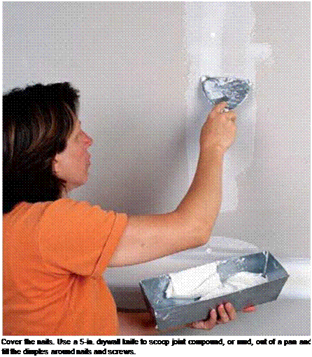
Подпись: Tape the seams. Apply joint compound along the seams between sheets, then lay drywall tape over the center of the joint. Use a 5-in. knife to embed the tape in the mud. Clean up as you IIP go. When left lying around, scrap pieces of drywall crumble eas­ily, making a paper and powder mess that can be tracked all over a job site. Avoid this by cleaning up drywall as you go. Stack usable pieces so they are easily accessible.
Подпись:

mud buildup in the corners. Clean any excess compound from along the edges of the tape with your knife.

Inside corners and wall-ceiling joints are taped a bit differently than flat joints in a ceiling or wall. Use a 4-in. or 5-in. knife to apply an l/S-in.- thick layer of joint compound on each edge of the corner. Next, fold the tape at the crease and press it into the corner, flattening it as you go. Working on one edge at a time, press the tape against the drywall and into the mud with the taping knife.

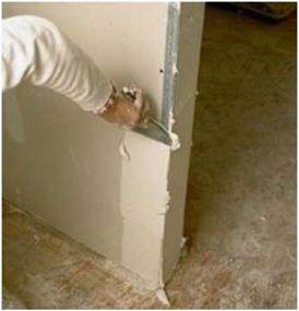
Outside corners covered with corner bead are easier to do (see the photo below). Using the same 4-in. or 5-in. knife, press mud along the length of the corner. The outside edge of the corner bead acts as a guide for your knife as you pull off excess mud.

The ends of a drywall sheet are not tapered like the edges are. For this reason, you should use less mud to cover the tape at the butt joints, where the ends of adjoining sheets meet. Otherwise, you can create an obvious bump in the wall. Cover the tape lightly with mud, and feather the edges away from the center of the joint so any bumps that result will be slight.

In hot, dry climates, joint-compound ap­plications dry rapidly. Mud that dries too fast may not bond well and can crack. Try mudding a couple of joints in a room and then applying

Do the prep work

tape right away, rather than mudding every joint first. You may need to close up the house to retain moisture and create a slower drying time. You can also use an easy-to-sand setting com­pound that hardens with little shrinkage and is basically unaffected by hot, dry conditions.

It’s a different story in cold and humid areas. Builders in those regions often have to close up the house, turn up the heat, and open the windows a bit to let out moisture. Portable propane heaters work well to help things dry, but they exhaust additional moisture into the air. If you’re using them, leave a window open so moist air can escape. Kerosene heaters also work well, but it may take a while for the smell to leave the house.

Mud the corner beads. Apply joint compound gen­erously along each side of a corner bead. To level off the compound, run the taping knife over the rounded outside edge of the bead. [Photo by Charles Miller, courtesy Fine Homebuilding magazine © The Taunton Press, Inc.]

AND FINISH THE DRYWALL

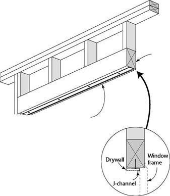
Подпись: HeaderПодпись:AND FINISH THE DRYWALLПодпись:Подпись: Using J-channel around a window makes a clean joint between the drywall and the window frame.Подпись: Dispose of waste drywall. Before you send waste drywall to a landfill, contact the Gypsum Association (see Resources on p. 279) to see whether there's a recycling facility in your area. Local builders may also know of recycling possibilities that can help reduce the amount of construction material sent to landfills.

straight, finished edge. Both metal and vinyl corner beads are designed to be nailed or stapled in place. Use tinsnips to cut floor-to-ceiling beads. Cut them at least V2 in. short, but hold them tightly against the ceiling. Starting at the top and working down, fasten the bead to the corner stud (below the top plates) with pairs of nails or screws opposite each other every 8 in. to 10 in. A pneumatic stapler also works well. Make sure all the beads are straight and lie flat against the wall.

Beads around windows and doors are at­tached just like those on corners. The header beads are cut square on both ends and then nailed in place. The side trimmer pieces are also cut square and butt into the top piece (see the photo at right).

I am not a professional drywall finisher, but I have taped enough wall and corner joints to know that this job is both an art and a skill. Some finishers can leave walls and ceilings as straight and smooth as glass. To the trained eye, my work looks more like antique, handmade glass—generally flat, but with some rippling and variations that give it character. The thing to remember, regardless of your skill level, is that taping drywall is finish work, so it needs to look good. Although your first efforts aren’t likely to be masterful, with patience and know­how you can learn to achieve good, solid work. This section will give you the basic know-how. The patience you’ll have to provide yourself.

AND FINISH THE DRYWALL

Install corner bead. This metal trim is nailed over drywall-covered outside corners. The flanges and nails will be covered by several coats of compound. Drive nails in both flanges every 8 in. to 10 in.

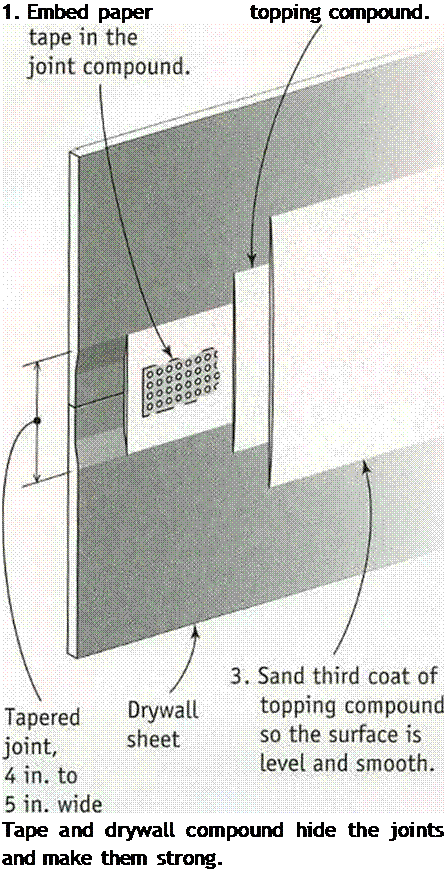
Подпись: ІІІІІІ1ШІІІІІІІІІІШІІІІІІІІІІІІІШІІШШШМІІІІІІІШІІШІІІІІ1ІІІІІІШІІ1ІІІІІІІІШІІІШШІШІІІШІШІІІІІІІІІІІШІІІШШШШІІІІІШІІІШІІІ TAPING AND MUDDING JOINTS Подпись: 2. Fill the low spots with 1. Embed paper topping compound. AND FINISH THE DRYWALL

Tool up for finishing drywall

Although professional drywall finishers rely on an assortment of equipment, including stilts to speed ceiling work, you can achieve very good results with just a few tools. You’ll find them at well-stocked hardware stores, home centers, and drywall-supply outlets.

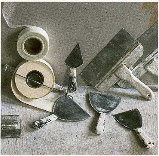
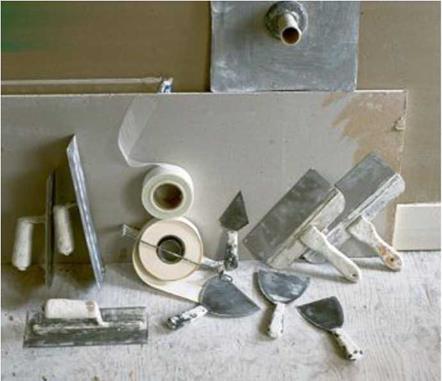
TAPING KNIVES. Mud applicators are called knives, even though they look more like overgrown spatulas. A 5-in.-wide knife is good for applying joint compound (referred to as mud). Wider knives are used to smooth and feather the edges of mud, tapering it so thin that it will be as undetectable as possible once the paint is applied. If you’re new to drywall work, start with 5-in., 8-in., and 12-in. knives for best results.

TROWELS AND HAWKS. These tools are simply flat pieces of metal with handles attached. Their main purpose is to hold a small batch of compound at the ready so that you can scoop it onto the wall with a taping knife. Trowels are rectangular, while hawks tend to be square. Which tool works best is a matter of personal preference. In the hands of an experienced worker, a trowel can be used to both hold and apply compound.

POLE SANDER. Sanding finish coats of compound is often necessary to smooth uneven areas. A pole sander consists of a sanding block attached to a pole. To sand the first two coats, cover the block with 120-grit sanding screens. When one side is dull, turn over the screen and use the other side. For the final sanding, switch to a 150-grit screen.

PORTABLE LIGHTS. With one or more bright, halogen-type work lights, you’ll have a much easier time finding flaws in the top coat. DUST MASK AND GOGGLES. Don’t begin to sand drywall compound without donning safety gear.

Use tape and knives for their respective tasks.

Tape—either paper or plastic—is used to cover the joints. Different-size knives are used to apply and level drywall compound. [Photo by Charles Miller, cour­tesy Fine Homebuilding magazine © The Taunton Press, Inc.]

Tape and drywall compound hide the joints and make them strong.

Подпись: Reuse joint- compound buckets. These rugged, plastic buckets are great for storing tools and materials. Wash out any remaining joint compound with water.

From fear of the Yellow River to the first grand irrigation projects (7th to 5th centuries BC)

The first large dike construction projects on the lower course of the Yellow River date from the spring and autumn period, more precisely the first half of the 7th century BC. The duke Huan de Qi is said to have brought together the “nine rivers” described by Sima Qian into a single course and probably tried to drain the swampy plain.[388] Soon after came the first realignment of the river course mentioned in Chinese history. In 602 BC the river adopted a new course some hundred kilometers to the east (Figure 8.2). Fortunately, the region affected by this first event was probably not very populated. The north of the allu­vial plain does not begin to see real development until the beginning of the warring states period (in the 5th and 4th centuries BC) when the Qi enters a new era of great prosperity. This will become one of the most active agricultural regions under the Qin and the Han.

The Yellow River is intensely present in Chinese thought during the feudal period; it is worshipped like a god. In some places a young girl is sacrificed to the river each year, such as at Ye, on the ancient course of the river that flows toward the north[389] in the Handan region (Figure 8.3). The girl is chosen by witches of the cult of the river, adorned as for marriage, placed on a wedding bed, then launched onto the river where the bed floats for a brief time, then sinks to drown the sacrificial maiden.[390] A certain Ximen Bao, a disciple of Confucius, was responsible for ending this practice. This end occurred under the enlightened reign of the duke Wen of the Wei kingdom (424 – 387 BC), a period during which this kingdom reached its apogee. We cannot resist the temp­tation to share the account of this event:

“Ximen Bao, having arrived in Ye, called together the notables and asked to learn about the custom that was desolating the county; marrying girls to the Lord of the River; the ceremony was described to him; he asked that he be told, without fail, of the day the festival would take place. When the day came, he and his soldiers went to the site of the sacrifice and announced that he came to be sure that a beautiful girl was chosen for the Lord. He looked at the girl chosen for sacrifice and declared to the grand wizard and to the elder of the country that the girl was not at all beautiful: he then sent the wizard to warn the Lord of the River that there was a mistake, that another would be chosen and that the ceremony was put off. The soldiers then threw the grand wizard into the river. Ximen Bao waited for a moment and, when the grand wizard did not come back from his mission, he threw an apprentice wizard into the river, then, when he did not return, a second apprentice, and finally a third. He then had the elder thrown into the river, and he did not return either. [….] Ximen Bao

From fear of the Yellow River to the first grand irrigation projects (7th to 5th centuries BC)

Figure 8.3 The basins of the Yellow River and the Blue River, from the time of the Warring States up to the early Han Empire. The underlined upper-case names refer to these states after 350 BC. The underlined names in italics refer to the regions, more ancient, of the Spring and Autumn period. Grand irrigation projects of the feudal period:

Irrig 1: between the Jiang and the Yellow Rivers (Ximen Bao)

Irrig 2: Zhengguo canal and derivation canals (Zheng Guo)

Irrig 3: Min basin – Figures 8.5 and 8.6 (Li Bing)

then stopped the ceremony and no one dared speak of resuming it.”[391]

Ximen Bao is also known for the development of irrigation in the Ye region, on the lower slopes of the Thaihang mountains. Around 410 BC he had dug what amounts to a canal fed by the Jiang (an earlier tributary of the Yellow River), rising toward the north­east on a course parallel to and above that of the ancient bed of the Yellow River. Secondary canals then provided for gravity irrigation of all the region between this der­ivation and the Yellow River, a region that becomes particularly prosperous according to Sima Qian.[392]

Further to the south the first dam-reservoir known in China is constructed around 585 BC, in the state of Chu. It is intended to support irrigation, and is attributed to the minister Sun Shuao. The earthen dam is reinforced with layers of straw and wooden stakes. The dam was originally called the Shaobei (dam of the Peony flower), but it is known today as the Anfengtang, for it is still in service. It blocks a large valley of rather gradual relief into which flow two southern tributaries of the Huai, coming down from the mountains that separate the valley of the Hua from that of the Yangtze.[393] [394]