MECHANICALLY STABILIZED EARTH WALLS

8.5.1 Types of MSE Walls

Mechanically stabilized earth (MSE) walls are made up of several elements—specifically, the reinforcement of a soil mass through the use of steel strips, steel or polymeric grids, or geotextile sheets, capable of withstanding tensile forces, and a facing material. Figure 8.25 depicts different types of geosynthetic reinforced walls. The walls depicted range from a sloping geotextile wrapped face, usually used for the more temporary

Vertical cast-in-place Vertical masonry facing

concrete/masonry facing

FIGURE 8.25 Facings for geotextile-reinforced walls.

conditions, to stabilized soil masses faced with more long-term cast-in-place concrete or masonry block facings.

The advantages of MSE walls over the more conventional reinforced concrete walls include

1. Inherent flexibility to accommodate reasonable differential settlements

2. Lower total cost

3. Less construction time

4. Inherent capability to provide drainage to avoid buildup of hydrostatic forces

The reinforcement elements are characterized as extensible or inextensible. Extensible reinforcements can deform without rupture to develop deformations greater than can the soil in which they are placed. Such reinforcements include polymeric geotextiles and geogrids. Inextensible reinforcements cannot deform to deformations greater than the soil they reinforce. Metallic-strip or grid reinforcements are included in this category.

A summary of the available MSE systems in terms of the reinforcement and facing panel details is included in Table 8.4. The summary includes the major proprietary systems available. Figure 8.26 includes data regarding the geometries and some mechanical properties of the different reinforcement types available for use in MSE walls with geotextile reinforcements.

Reinforced Earth was invented by Henri Vidal, who first published results of his studies in 1963. After a brief period of skepticism, the first significant projects were constructed in 1967. The use of Reinforced Earth then spread rapidly, and by the early 1970s many significant projects were in place in several countries. These included the 23-m-high Peyronnet wall on the Nice-Menton Highway and the coal and ore loading facility at the port of Dunkirk, in France; the major retaining walls built along California Route 39 and along Interstate 70 through Vail Pass in the Colorado Rocky Mountains, in the United States; the Henri Bourassa Interchange in Quebec City, Canada; the several retaining walls on the Bilbao-Behobia Expressway in Spain; and the 11-km-long wall built on the St. Denis coastal road on Reunion Island in the Indian Ocean. Subsequently, Reinforced Earth has been accepted by civil engineers in all of the world’s industrialized nations, and its uses have been greatly diversified. Predominant applications are high­way and railway retaining walls and bridge abutments.

As indicated in Table 8.4, several other systems have been used since the introduction of Reinforced Earth. The Hilfiker retaining wall, which uses welded wire reinforce­ment and facing, was developed in the mid-1970s, and the first experimental wall was built in 1975 to confirm its feasibility. The first commercial use was on a wall built for the Southern California Edison Power Company in 1977 for repair of roads along a power line in the San Gabriel Mountains. In 1980, the use of welded wire wall expanded to larger projects, and, over the years, numerous walls have been completed in the United States.

Hilfiker also developed the Reinforced Soil Embankment (RSE) system, which uses continuous welded wire reinforcement and a precast-concrete facing system. The first experimental Reinforced Soil Embankment system was constructed in 1982. The first use of RSE on a commercial project was in 1983, on State Highway 475 near the Hyde Park ski area northeast of Santa Fe, New Mexico. At that site, four reinforced soil structures were constructed totaling 17,400 ft2 (1600 m2) of wall face. Many addi­tional RSE systems have been constructed since.

A system using strips of steel grid (or “bar mat”) reinforcement, VSL Retained Earth, was first constructed in the United States in 1981 in Hayward, California. Since then, numerous VSL Retained Earth projects have been built in the United States.

TABLE 8.4 Reinforcement and Face Panel Details for Several Reinforced Soil Systems Used in North America

Reinforcement

System name detail

System name

Reinforcement

detail

Typical face panel detail*

Maccaferri Terramesh system (Maccaferri Gabions, Inc., 43A Governor Lane Blvd., Williamsport, MD 21795) Geotextile reinforced system

Continuous sheets of galva­nized double-twisted woven wire mesh with PVC coating.

Continuous sheets of geotex­tiles at various vertical spacings.

Rock fill gabion baskets laced to reinforcement.

Continuous sheets of geotex­tiles wrapped around (with shotcrete or gunite facing). Others possible.

*Many other facing types are possible with any specific system.

Source: From J. K. Mitchell and B. R. Christopher, “North American Practice in Reinforced Soil

Systems,” Proceedings, Specialty Conference on Design and Performance of Earth Retaining Structures, Geotechnical Division, American Society of Civil Engineers, 1990, with permission.

The mechanically stabilized embankment, a bar mat system, was developed by the California Department of Transportation on the basis of its research studies starting in 1973 on Reinforced Earth walls. The first wall using this bar mat type of reinforce­ment system was built near Dunsmuir, California, about 2 years later. Here, two walls were built for the realignment and widening of highway I-5. Since then, California has built numerous reinforced soil walls of various types.

Another bar mat reinforcing system, the Georgia stabilized embankment system, was developed more recently by the Georgia Department of Transportation, and the first wall using its technology was built for abutments at the I-85 and I-285 inter­change in southwest Atlanta. Many additional walls have been constructed using this system.

Polymeric geogrids for soil reinforcement were developed after 1980. The first use of geogrid in earth reinforcement started in 1981. Extensive marketing of geogrid products in the United States was started about 1983 by the Tensar Corporation. Since then, many projects have been constructed using this type of reinforcement.

The use of geotextiles in reinforced soil walls started after the beneficial effect of reinforcement with geotextiles was noticed in highway embankments over weak sub­grades. The first geotextile reinforced wall was constructed in France in 1981, and the first structure of this type in the United States was constructed in 1974. Since about 1980, the use of geotextiles in reinforced soil has increased significantly.

The Zhengguo irrigation canal, in the basin of the Wei

Later on, probably around 250 BC, the king of the state of Hann felt menaced by the expansion of the Qin. He sought to deflect the warlike ideas of the Qin by turning his dangerous neighbor’s energy toward peaceful projects:

“The state of Hann, learning that the state of Qin was fond of undertaking large projects, dis­patched a water engineer named Zheng Guo to go to Qin and persuade the ruler to construct a canal from a point of the Jing river west of Mt Zhong to the pass at Hukou, and from there along the Northern Mountains east into the Luo River, a distance of over 300 li. Ostensibly the purpose of the project was to provide irrigation for the fields, though in fact Zheng Guo and the rulers of Hann hoped thereby to wear out the energies of the state of Qin so that it would not march east to attack Hann. Zheng Guo succeeded in getting the project started, but halfway through the real nature of the mission came to light. (…)

“The Qin ruler, deciding that this (the argumentation of Zheng Guo that the canal would ben­efit to the Qin) was sensible, in the end allowed him to go ahead with the canal. When it was finished, it was used to spread muddy, silt-laden water over more than 40,000 qing of land which up until this time had been very brackish, bringing the yield of the land up to one zhong

per acre (mu). As a result the area within the pass was converted into fertile land and no

longer suffered from lean years; Qin became rich and powerful and eventually was able to

3 5

conquer all the other feudal lords and unite the empire.”33

This canal, put into service in 246 BC, is more than 150 km long, and links the Jing to the Luo in Shaanxi (Figure 8.8). It is called the Zhengguo canal in honor of its builder, and supplies numerous secondary canals that provide gravity irrigation for the entire lower region. The canal has been rebuilt several times, even recently, with new intakes further up the course of the Jing to account for the progressive degradation of the river bed and the sediment deposits in the canal itself.

The irrigation system in the Min valley, Sechuan

In 316 BC the Qin occupy the land of Shu, in the southwest, as far as the middle course of the Yangtze river. They developed the basin of the Min River, a tributary of the Yangtze in the Sechuan depression. In the region of present-day Chengdu, they implement a gigan­tic program of irrigation works. Sima Qian mentions this project – all too briefly:

“In Shu, Li Bing, the governor of Shu, cuts back the Li Escarpment to control the ravages of

the Mo (Min?) River and also opened up channels for the Two Rivers through the region of 33

Chengdu.”

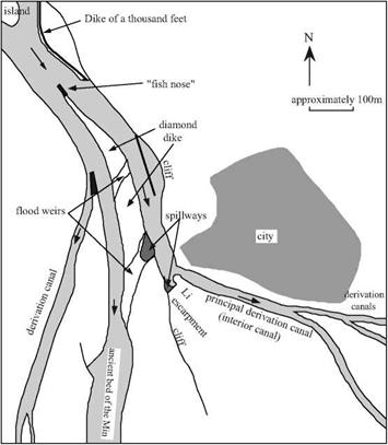
The crown jewel of this project is a remarkable intake structure on the Min (Figure 8.4),[398] near the city of Dujiangyan (earlier Guanseian). It includes a main dike (the dike of a thousand feet) that directs the current toward a structure built of large stone blocks, called the fish nose, that divides the river flow into two portions. The resulting two main channels are separated by the diamond dike whose crest is above the level of the floods, then by overflow structures that make it possible to spill floodwaters from the left chan­nel (whose bed is higher) toward the right channel, which occupies the ancient river bed.

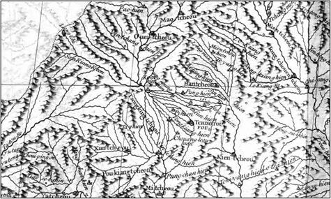
The left channel, or interior channel, is cut into rock across the hill that is some sixty meters in height, and on which the city of Dujiangyan is situated. Sima Qian speaks of the part of this hill that is isolated by the cut called the escarpment of Li. Further down­stream, along this same channel, numerous intake structures direct irrigation water toward Chengdu and the plain of Sechuan (Figure 8.5).

Подпись: Figure 8.4 The intake structure on the Min River at Dujiangyan, origin of the irrigation system of the Chengdu plain at Sechuan (after Needham, Ling, Gwei-Djen, 1971).
The irrigation system in the Min valley, Sechuan

It was surely Li Bing, the designer of the project, who also planned for its mainte­nance. During the low-water period from mid-October to the end of March the canals are cleaned out and the heights of weirs and dikes are brought back to their original lev­els. This maintenance requires that the two arms of the river be alternately dewatered with portable wood dams. In addition at regular intervals the fish nose, the main struc-

ture separating the two channels, is maintained.

Li Biing, along with his son who finished these works, is viewed as a benefactor by the inhabitants of the region. He becomes immortal; at the very top of the escarpment of Li, a Taoist temple is consecrated to him.

The irrigation system in the Min valley, Sechuan

Figure 8.5 The irrigation canals of the Chengdu region, detail from a map established by the Jesuits of the 18th century (Du Halde, 1735 – ancient archives of ENPC).

Fundamental Drainage Considerations

The drainage system employed in a road construction will depend on factors such as:

• The importance of the road;

• The amount of traffic;

Fig. 13.2 A horizontal alignment designed to lead water away from sensitive areas

• The zone (rural or populated);

• The sensitivity of the groundwater; and

• The sensitivity of streams, rivers and lakes.

Drainage systems can be classified as follows:

• Surface systems – these involve ditches and open channels in the surface of the ground;

• Subsurface systems – these are not directly accessible from the surface. Water is collected from water in the ground’s pore space and conveyed in trenches and pipes. Subsurface systems can be divided into shallow (interceptor) drains that collect percolating water above the water table and deep (water table lowering) drains.

In a very permeable soil, separate drainage may not be necessary, only provision of some capacity for immediate runoff and for snow and snowmelt.

Open channel drainage systems are favoured because of their low cost (compared with capacity), easy rehabilitation and maintenance. However, deep open ditches and steep inner road slopes can be dangerous for wandering vehicles, especially on a road with high traffic speeds. Steep slopes may also increase cracking along the centre of narrow roads, and, possibly, increase erosion and the need for channel cleaning.

Subsurface systems have advantages in special circumstances and can be efficient tools in road rehabilitation projects, especially when there is limited space available, limited support of slopes or a need to use deep drainage.

The correct depth for the drainage depends on the pavement thickness, the road layout (cutting or embankment), the type of subsoil and the climatic conditions (intensity of runoff, frost depth and snowmelt conditions). The drainage depth is usually the depth of all the layers of the road structure that contribute to the bearing capacity of the pavement.

Fig. 13.3 Drainage economics

The design of drainage is a part of the design of the whole road, so all aspects of the road can have an effect on it. Drainage design is, simply described, the action of finding an optimum balance between the total costs (investment and maintenance costs) compared to the possible advantages and disadvantages (pavement life, traffic safety, easy maintenance and wider environmental aspects) – Fig. 13.3.

Considering all these aspects, there are a number of steps which, in general terms can be considered fundamental. They are listed in the Portuguese Road Drainage manual as follows (IEP, 2001):

1st Step – Gather all the relevant information:

• Road importance (traffic flow values, status and whether a “lifeline” road);

• Geometric characteristics of the road (layout and profiles);

• Drainage areas and existing drainage systems;

• Geology;

• Meteorological data (precipitation, temperature, frost, etc.);

• Hydrological and hydrogeological conditions in the area surrounding the road (ground-water conditions); and

• Identification of specific constraints (technical, social, economic or envi­ronmental);

2nd Step – Identify critical/sensitive areas:

• Vulnerable areas with particular conditions, geological, environmental or ecological;

• Areas with a high frost formation probability;

• Specific areas of the road, such as high and low level points;

• Extreme gradient and cross fall situations; and

• Cutting/embankment transition areas.

3rd Step – Adopt standard/typical layouts, where possible, for road segments with similar characteristics.

4th Step – Define the basic data for the water flows in each layout, using existing methods, tables and software to perform necessary calculations.

5th Step – Analyze the possible and adoptable solutions, based on standard drawings and typical dimensions used in each region or country.

6th Step – Perform the hydraulic calculations so as to obtain drainage sizes. If the estimated amount of water is small, exact hydraulic calculations may not be needed.

7th Step – Consider the location of the discharge points, as well as the need to design retention and/or treatment basins, which may be associated with individual drainage systems.

Roads are normally constructed with two types of drainage systems, the surface and the subsurface drainage systems, each taking care of their separate sources of water and moisture.

Requirements for Airfield Pavements

Requirements concerning wearing courses of airfield pavements are defined as fol­lows (namely, in the regulations of the U. S. Federal Aviation Agency (FAA) Advisory Circular AC No. 150/5370-10B):

• Be impermeable to water and suitably protect intermediate course.

• Provide surface free of foreign object damage (FOD) (i. e., loose particles).

• Resist loads from aircrafts.

• Be smooth, with uniform surface.

• Maintain required antiskid properties.

• In specific areas should be resistant to spillage of fuel, hydraulic and deic­ing fluids, or other solvents.

Guidelines on specifications for pavements on civil installations are contained in

International Standards and Recommended Practices, AERODROMES. Annex 14 to the Convention on International Civil Aviation, Volume I—Aerodrome Design and Operations by the International Civil Aviation Organization (ICAO). The ICAO regulations regarding civil aerodromes mainly define the features of pavements affecting air traffic safety—minimum level of friction, sufficient smoothness, lack of presence of any loose particles (i. e., FOD) or grains bigger than 3 mm resting on the pavement.

The rules of the FAA and ICAO govern the methods and frequencies of testing the friction and macrotexture. Methods of permanent measurement of the friction factor described in both documents will not be referred to here. Measurements of macro­texture are usually carried out either with calibrated sand (sand patch test) or with the application of special greases (NASA grease smear method). The minimum sur­face texture depth recommended by the ICAO is 1.0 mm. It is worth noting here that the essential task of macrotexture is to enable water discharge from the pavement so that a layer of water does not build up between a wet runway and an aircraft’s tire (hydroplaning).

Bearing in mind that a newly paved, ungritted SMA layer is marked by a high degree of slipperiness, some problems with achieving the intended level of friction may develop. On the other hand, gritting, even when followed by sweeping with mechanical brooms to remove unbonded grains, gives rise to a real threat to air­planes due to FOD; thus gritting has generally been ruled out. So the proper level of friction to be obtained by an adequate grain size distribution and the application of coarse aggregate with a high polished stone value (PSV) index.

Requirements for asphalt mixes for airfields mainly comply with specifications for highway engineering in some countries; however in other countries, special tech­nical requirements have been drawn up specifically for airfields. They differ from those for highway applications. But, in each case the ICAO specifications for the finished pavement should be satisfied.

One should also remember that binders applied to specified parts of airfield pave­ments should be checked for resistance to fuel and deicers because of the destructive actions of these substances. Some manufacturers of road binders offer special prod­ucts for such applications. Also some research has been done in this area (Steernberg et al., 2000). The following two documents in a series of European Standards estab­lished adequate methods of testing:

• EN 12697-41, Asphalt Mixtures—Test Methods for Hot Mix Asphalt—Part 41: Resistance to Deicing Fluids

• EN 12697-43, Asphalt Mixtures—Test Methods for Hot Mix Asphalt—Part 43: Resistance to Fuel

According to EN 13108-20, the aforementioned tests of resistance to deicing fluids and fuels are specifically applicable to SMA used on airfields.

Choose an exterior finish

Wood siding, such as shingles or clapboard, is often better off when finished with stain rather than with paint. Solid-color exterior stain gives wood a paintlike appearance, hut it does not crack or peel the way paint can. To let more of the wood grain show through, use semitransparent stain, which is available in many wood tones and colors.

Whether you choose paint or stain, make sure you buy a good-quality finish that is rec-

SET THE NAILS. Before paint­ing any trim, use a hammer and nail set to drive all nails about Vs in. below the surface of the wood. Fill the holes with wood putty and sand them smooth.

Подпись:Choose an exterior finish

ommended for the use you have in mind. For example, you don’t want to paint a deck with porch enamel or use interior trim paint on exterior wood. The pressure-treated lumber used on many decks needs a penetrating sealer or stain rather than paint. Upright pressure – treated porch posts can be painted or stained with a solid color once the wood is clean and dry. Find out which brands and formulations knowledgeable painters and paint suppliers in your area recommend.

Do the prep work for exterior finishes

Exterior siding and trim must be painted on all sides, not just on the surfaces that will be
exposed to the weather. Back-prime the trim before installation. On doors and windows with wood casings, make sure you back-prime all casings before installing the unit.

Take the time to fill all nail holes with exterior-grade wood putty. Don’t caulk under the lap between siding boards or where siding meets trim because you don’t want to trap water behind the siding. There is no need to caulk or seal under the lap between siding boards because any moisture that gets behind the siding can drain out between the laps. Always use a good-quality, long-lasting, paint- able, exterior-grade caulk. Mask and cover any decks or railings to protect them from drips and spills. Cover the foundation or walkways to keep paint from staining the concrete. Take the time to do it right. There is no excuse for being sloppy with paint. Drops of paint on a wood deck or concrete foundation will look bad for years to come.

Apply exterior paint

Much can be done with exterior paint to give a house a classy style. There is an old house in our neighborhood that has just been repainted lavender with light-violet trim. Now, this may not be your choice of colors, but it brightens up our neighborhood in a nice way. 1 like it bet­ter than the Coos Bay gray that makes so many buildings look like army barracks. A good

Choose an exterior finish

You can’t have too many volunteers when it’s time to paint. . .

We use brushes and rollers of all different sizes. . .

Painting a new house is great because you don’t n to worry about getting paint on carpets and furniture People with rollers paint the walls and ceilings qu but it’s just as satisfying to work on trim with a brus

Choose an exterior finishChoose an exterior finish

PAINTING DOORS

Подпись: Turn the door over to paint the other side.Choose an exterior finishПодпись: Drive 16d nails temporarily into the top and bottom of the door. Rest the nails on sawhorses and paint one side of the door, then the other.

choice of colors can make a home warm and inviting. Some paint dealers have a computer program that shows you what different color combinations will look like on your house.

Give your house a virtual paint job to test out various color schemes.

Once you have selected the color, try rolling paint on lap siding with a roller that matches the width of the laps. Once the paint has been rolled on, it must be brushed in to make sure every crack and crevice is covered properly. Take special care when painting the bottom edges of siding. These edges must be well coated because it is where moisture and ice gather.

Latex paint dries rapidly in hot weather, so don’t roll on too much paint before you go back over it with a brush. Remember, too, that most paints require a wall temperature of at least 50°F or so for good adhesion, so don’t paint if the weather is cooler than that.

Completely paint or stain the siding before you tackle the exterior trim, just as you did on the interior. Use a good brush and a steady hand to leave a neat-looking job. Doors get a lot of use, so it’s best to give them at least a couple of coats on top of the primer. The metal-clad exterior doors that are often used unaffordable houses come with a prime coat. You may want to use a higher gloss paint on doors because it is easy to clean.

Instead of trying to paint doors in place, take them down and remove all the hardware. Put the hardware for each door in a small plastic bag, label the bag, and store it in a kitchen drawer. Label the door, too. The top edge is a good place to write the door’s loca­tion. Drive nails or screws into the top and bottom edges, then set the door across a pair oi sawhorses (see the illustration above). After painting one side, flip over the door and paint the other side. Set the door aside, resting it on the nails, while you paint another door. Wait


until the first coat is dry, then apply a second coat, brushing out any streaks or drips. When you’re done, remember to put a bit of caulk in the top nail holes so water can’t enter.

Door jambs are also easier to paint when there’s no door in the way. On some exterior entries, weatherstripping is installed on the door; on others, it’s installed on the jamb. Either way, it’s usually best to remove weather­stripping before painting instead of trying to paint around it. Getting paint on weather­stripping can prevent it from sealing properly. If the weatherstripping is damaged or difficult to reinstall, just buy new material. It is gener­ally inexpensive and is important for sealing the interior of the house from the elements.

Once you are finished painting, use a small piece of cardboard to scrape all unused paint into one can. Save some paint for later touch-up work. A contractor I know takes leftover cans of latex paint, stirs them together, and uses the mixture as back-primer for the next job. Some cities have a site where you can drop off paint for recycling. Otherwise, take unused paints, stains, and solvents to a hazardous-waste facil­ity. Give the earth a break. Don’t dump toxic materials on the ground or down the sink.

і

Design Procedures for a Cantilever Retaining Wall

A typical cantilever retaining wall is illustrated by the insert sketch in Fig. 8.21. This rigid-type wall can be constructed with or without a base shear key (see Fig. 8.20) depending on an analysis for resistance to sliding, as discussed later.

The specifications of the owner will govern the selection and use of backfill materials behind retaining walls. In most cases, clean backfill materials having an internal friction angle of at least 34° are assumed in the design of retaining walls, subject to the fol­lowing considerations:

1. With a proper drainage system and with backfilling controlled so that no compaction-induced lateral loads are applied to the wall, the above-noted or better material may be used in construction. A minimum lateral earth pressure of 30 (lb/ft[10] [11])/ft (4.7 kN/m[12]) (equivalent fluid weight) for level backfills, or 40 (lb/ft2)/ft (6.3 kN/m3) for 2:1 sloped fills, should be assumed.

2. Backfill is assumed as on-site inorganic material; however, if it is of a lower class designation, the wall must be designed for an equivalent fluid weight lateral pressure suitable for that class. Therefore, should the designer select a backfill material of lower classification, it will be necessary to clearly specify the backfill material by a supple­mental project special provision and to use an appropriate equivalent fluid weight lateral pressure for design.

The design aids provided in Figs. 8.22 and 8.23 may be used for preliminary dimen­sions in the design of a cantilever cast-in-place retaining wall. On the basis of the Rankine theory of earth pressure, final design may proceed with the following steps:

NOTES:

Class I backfill (see Fig. 8.41)

Class D concrete

Coef. of friction (soil to soil = 0.67, soil to concrete = 0.42)

FIGURE 8.22 Aid for preliminary design of cast-in-place concrete retaining walls showing wall and footing dimensions. (From Bridge Design Manual, Section 5, Colorado Department of Transportation, Denver, Colo., with permission)

width b is approximately one-third to one-half of B. The ratio of footing width to overall height should be in the range from 0.4 to 0.8 for T-shaped walls as shown by the design aids in Figs. 8.22 and 8.23. In these preliminaries, wide-base L-shaped walls (footing width to height ratios larger than 0.8) are used for low wall heights (less than 10 ft or 3 m), and the factor of safety with respect to overturning is relaxed from a minimum of 2.0 to 1.5 when considering the case of D + E + RI.

4. Draw a vertical line from the back face of the footing to the top of the fill. This line serves as the boundary of the free body to which the earth pressure is applied. The applied active earth pressure can be estimated by Rankine theory, and the direction assumed parallel to the backfill surface. Compute the resultant P of the applied earth pressure and associated loads. Resolve P into horizontal and vertical components Ph and Pv, and apply at one-third the total height Ht of the imaginary boundary from the bottom of the footing. (See Fig. 8.21.)

5. Take a free body of the stem and compute the loads applied at the top of the stem as well as loads along the stem (height H), and find the moment and shear enve­lope to meet all the design cases at several points along the height. The working stress design method and the concept of shear friction can be used to calculate the shear strength at the joint between footing and stem.

Wall height at stem (ft)

NOTES:

Class I backfill (see Fig. 8.41)

Class D concrete

Coef. of friction (soil to soil = 0.67, soil to concrete = 0.42)

FIGURE 8.23 Aid for preliminary design of cast-in-place concrete retaining walls showing toe pressure and steel and concrete quantities. (From Bridge Design Manual,

Section 5, Colorado Department of Transportation, Denver, Colo., with permission)

6. Calculate the weight W, which is the sum of the weight of concrete and the weight of soil bounded by the back of the concrete wall and the vertical line defined by step 4 above. Find the distance from the extremity of the toe to the line of action of W, which is the stabilizing moment arm a.

7. Calculate the overturning moment Mo applied to the wall free body with respect to the tip of the toe as:

(8.5)

Calculate the resisting moment Mr with respect to the tip of the toe as:

M = Wa + P B

r v

The safety factor SF against overturning is

Mr

SF (overturning) =——-

M

o

Wa + P B

Ph H, /3

h t

The required safety factor (overturning) should be equal to or greater than 2.0 unless otherwise accepted and documented by the engineer (see step 3).

8. Compute the eccentricity e of the applied load with respect to the center of the footing based on the net moment:

The resultant should be within the middle third of the footing width; i. e., the absolute value of e should be less than or equal to B/6 to avoid tensile action at the heel.

9. The toe pressure q can be evaluated and checked by the following equation:

The toe pressure must be equal to or less than the allowable bearing capacity based on the soils report. Toe pressure is most effectively reduced by increasing the toe dimension.

10. The footing, both toe and heel, can be designed by working strength design. Soil reactions act upward and superimposed loads act downward. The heel design loads should include the portion of the vertical component Pv of earth pressure that is applied to the heel. For the toe design loads and stability, the weight of the overburden should not be used if this soil could potentially be displaced at some time during the life of the wall.

11. Check the factor of safety against sliding without using a shear key. The coef­ficient of friction between soil and concrete is approximately tan (/3ф), where ф is the internal friction angle of the soil in radians. Neglect the passive soil resistance in front of the toe. The sliding resistance SR can be evaluated as:

SR = (W + Pv) tan (|ф) (8.10)

The SF (sliding), which is SR/Ph, should be equal to or greater than 1.5. If SF (sliding) is less than 1.5, then either the width of the footing should be increased or a shear key should be installed at the bottom of the footing.

If a shear key is the choice, the depth of the inert block dc is computed by the sum of the key depth KD and the assumed effective wedge depth, which is approximately half the distance between the toe and the front face of the shear key (b/2). Using the inert block concept, knowing the equivalent fluid weight (yp) of passive soil pressure, and neglecting the top 1 ft (300 mm) of the toe overburden T, the toe passive resistance P is

p

Pp = 0.57p[(To + T + dc — 1)2 — (To + T — 1)2] (8.11)

Total sliding resistance F from friction is the sum of the horizontal component of the resistance from toe to shear key and the resistance from shear key to heel. Therefore:

where ф = internal friction angle of base soil

R1 = soil upward reaction between toe and key, lb/ft (kN/m) R2 = soil upward reaction between key and heel, lb/ft (kN/m)

Sliding resistance is

SR = F + Pp (8.13)

The SF (sliding), which is SR/Ph, should be equal to or greater than 1.5.

12. Repeat steps 3 through 11 as appropriate until all design requirements are satisfied.

Figure 8.24 represents typical values for equivalent fluid pressures of soils. These values are suggested for use in the absence of a more detailed determination.

Structural backfill class designation

Type of

soil (compaction conforms with AASHTO 90-95% T180)

Typical values for equivalent fluid unit weight of soils, lb/ft3abc (kN/m3)

Condition

Level

backfill

2:1 (H: V) backfill

Class Id: borrowed,

Loose sand or gravel

(Active)

40

50 (6.3/7.9)

selected, coarse-

(At rest)

55

65 (8.6/10)

grained soils

Medium dense sand or

(Active)

35

45 (5.5/7.1)

gravel

(At rest)

50

60 (6.3/9.4)

Dense6 sand or gravel,

(Active)

30

40 (4.7/6.3)

95% T180

(At rest)

45

55 (7.1/8.6)

Class IIAf: on-site,

Compacted, clayed,

(Active)

40

50 (6.3/7.9)

inorganic, coarse-

sand gravel

(At rest)

60

70 (9.4/11)

grained soils, low

Compacted, clayed,

(Active)

45

55 (7.1/8.6)

percentage of fines

silty gravel

(At rest)

70

80 (11/13)

Class IIB: on-

Compacted, silty/sandy

Site-specific material, use with

site, inorganic

gravelly, low/medium

special attention;

see geotech-

LL < 50%

plasticity lean clay

nical engineer. Soils report on

workmanship of compaction,

drainage design, and waterstop

membrane is required.

Class IIC: on-

Fat clay, elastic silt that

Not recommended

site, inorganic

can become saturated

LL > 50%

a At rest, pressure should be used for earth that does not deflect or move.

b Active pressure state is defined by movement at the top of wall of 1/240 of the wall height.

c The effect of additional earth pressure that may be induced by compaction or water should

be added to that of earth pressure.

d Class I: 30 percent or more retained on no. 4 sieve and 80 percent or more retained on no.

200 sieve.

6 Dense: No less than 95 percent density per AASHTO T180.

f Class IIA: 50 percent or more retained on no. 200 sieve.

FIGURE 8.24 Typical values for equivalent fluid pressure for soils. (From Bridge Design Manual,

Section 5, Colorado Department of Transportation, Denver, Colo., with permission)

Special Applications of SMA

This chapter describes some special applications of stone matrix asphalt (SMA). Several brief case studies illustrate some of the less common, though advantageous, ways SMA mixtures can be used and also suggest some areas where they should be used with caution.

13.1 AIRFIELD PAVEMENTS

According to a report by the European Asphalt Pavement Association (EAPA), asphalt surfacing covers the majority of runways (EAPA, 2003). The high perfor­mance of SMA pavements has been attracting the attention of airport management, creating the chance to apply SMA technology in wearing courses of airfield pave­ments. Numerous trial sections have sprung up on various airfields (e. g., Sydney, Australia, and Johannesburg, South Africa). Some important, larger applications of SMA may be seen in Frankfurt on the Main, Germany, and Gardermoen near Oslo, Norway. The airfield in Frankfurt will be described in detail later on, not only for the SMA technology itself but for its application.

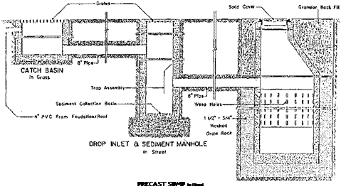
STORM WATER DRY SUMP

Подпись: PRECAST SUMP In Street

Portland, Oregon In North Meadow Village, developed

and built by Black Bull Enterprises in Portland, Oregon, the developer proposed changes deleting 630 feet of storm sewer pipe and adding an effective means of groundwater recharge.

A system of swales was designed to convey runoff into three on-site sumps where it could soak into the soil. Where storm sewer pipe was required, PVC was used in place of concrete pipe. The combination of savings from each change in the storm drainage system resulted in a savings of $6,350. ITus was equivalent to a per unit savings of $742.

Drainage for Cimarron, developed and built by Knoell Homes, Inc., was primarily above ground. Concrete valley gutters were used in some streets, and normal street curbs and gutters in other streets to direct stormwater to a channel and then to retention basins. The retention basins further created a visually attractive entrance to Cimarron. This drainage plan saved $70,578 over the original plan which required some underground drainage through an 18-inch concrete pipe, and a, pumping station to lift stormwater to an existing canal.

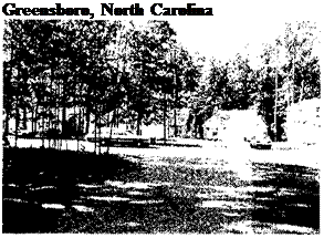
Подпись: жПодпись: Phoenix, ArizonaПодпись: Cimarron entranceSTORM WATER DRY SUMPПодпись:In Covington Place, builder/ developer Norcon Builders, Inc., eliminated typical Greensboro curbs and gutters. Ninety percent of the stormwater is absorbed by grassy swales along the sides of the streets and filters into natural areas on the site. This design saved approximately $200 per unit, and added to the attractive, woody, natural feeling of the subdivision.

Charlotte, North Carolina Stormwater in Lynton Place, John

Crosland Company builder and developer, is carried by grassy swales to a retention pond, with culverts used where necessary. This saved $16,390 compared to the curb, gutter, and piping system normally used in Charlotte.

The following demonstrations also used grassy swales instead of the typical locally accepted culverts for storm­water drainage: Oklahoma City, Oklahoma, and Knox County, Tennessee.

Overall Stability on Weak Soils

Where retaining walls are underlain by weak soils, the overall stability of the soil mass containing the retaining wall should be checked with respect to the most critical surface of sliding. A minimum safety factor of 2.0 is desirable but may not always be achievable. A technique known as slip circle analysis can be used to check for global stability. Refer to standard texts on soils engineering.

TABLE 8.3 Relationship between Soil Backfill Type and Wall Rotation to Mobilize Active and Passive Earth Pressures behind Rigid Retaining Walls

Wall rotation, Д/Н

Soil type and condition

Active

Passive

Dense cohesionless

0.001

0.020

Loose cohesionless

0.004

0.060

Stiff cohesive

0.010

0.020

Soft cohesive

0.020

0.040

Source: From Design Manual, Part 4, Pennsylvania Department of Transportation, Harrisburg, Pa., with permission.