Preparing Surfaces

Surface prep determines how well coverings adhere, hence how good the job looks and how long it lasts. Ideally, surfaces should be clean, dry, flat, and stable. Before hanging wallcoverings, assess existing surfaces; remove, replace, or repair them as necessary; and then prime and seal them. Sealing surfaces improves adhesion and, just as important, allows you to remove coverings later without destroying the underlying drywall or plaster.

In the old days, a wall was sized, or brushed with a glutinous mixture to improve the adher­
ence of the wallpaper. But sizing is rarely done today because it’s chemically incompatible with many pastes, causing them to crystallize, lump, and bubble, creating voids where the covering is unattached. Instead, professionals use one of the primer-sealers described in "Primer-Sealers for Wallcoverings,” below.

Before you start prep work, move furniture from the room or move it to the room’s center and cover it with a tarp. That will allow you to work faster and be safer. О Speaking of safety, always use a voltage tester to be sure electrical power is off where you’re working. Also set up ladders and scaffolds so they don’t wobble. Wear a respirator mask when applying chemicals, and clean up waste as you go.

WALLCOVERINGS

Wallpaper, actual paper, is most appropriate for historically accurate restoration and wherever you want fine detail. Although vinyl coverings are increasingly hard to distinguish from paper, vinyls tend to look glossier. Although paper may have an aesthetically pleasing flat finish, it is more vulnerable to grime and abuse.

Vinyl is today’s workhorse, available in a dizzy­ing range of patterns and in finishes ranging from flat to glossy. Vinyl is especially suitable for areas with traffic and moisture. Most vinyls are washable, and cloth-backed vinyls are usually strippable—that is, they are easily removable when you want to change them. Although no wallcovering is intended to conceal major cracks and irregularities, heavier vinyls can conceal minor ones.

Fabric coverings include cotton, linen, silk, stringcloth, and wool. They’re often chosen to match or coordinate with colors and textures in drapes and fabric-covered furniture. They come paper-backed, acrylic-backed, or unbacked (raw). And the backing largely determines the method of installation. Avoid slopping adhesive or water onto the fabric facing because some fabrics stain easily; delicate fabrics are usually dry hung, in which paste is applied to the wall and the dry wallcovering is smoothed onto it, as explained on p. 477.

Natural textures such as rice paper, grasses, and bamboo tend to be expensive, temperamental, and delicate. And because the thinner coverings reveal even minor flaws in wall surfaces, you first need to cover the walls with a lining paper. Still, natural textures are evolving, with vinyl-coated versions that are relatively durable and easy to install. Besides their beauty, most natural tex­tures have no pattern that needs matching.

Foils and Mylars also vary greatly in appearance and ease of handling. For example, heavier, vinyl-laminated foils are durable and easy to

A Wall OF YOUR OWN

Thanks to technology, you can have wall cover­ings fabricated with virtually any pattern

or image you want, including historical docu­ments or wall-size photos of family members.

The cost has come down a lot. Make sure that

such coverings are treated with a protective

coating, so they will wear well.

image946

install. However, some uncoated metallic cover­ings retain fingerprints, so you should wear gloves when hanging them, or perhaps avoid them altogether. That said, foils are well suited to small rooms because they reflect light, thus mak­ing the space appear larger.

Lincrusta, an embossed wallpaper similar to a fine cardboard, is making a comeback. The mod­ern version of Victorian lincrusta is called anaglypta.

Cork and wood-veneer wallcoverings are finely milled and manufactured to use cork and rare woods efficiently. Typical veneer dimensions: /64 in. thick, 1 ft. to 4 ft. wide, 12 ft. long. Such specialty coverings may be available through suppliers of professional paperhangers.

Borders are thin strips of wallcovering that run along the edges of walls where they meet ceilings, wainscoting, and trim. They can be installed over wallcovering or directly to drywall or plaster. The surface determines the adhesive.

PASTES

Like wallcoverings, pastes have evolved. Probably the best advice is to follow the manufacturer’s paste specifications, usually printed on the wall­covering label, along with the code and run num­bers. If the paste isn’t specified, ask your supplier to get that information from the manufacturer.

Wheat pastes were the standard for centuries, but that changed in the 1960s and 1970s, with the introduction of vinyl wallcoverings. Trapped behind an impervious skin of vinyl, wheat paste was an ideal medium for mold. Moreover, wheat
paste wasn’t strong enough to adhere many of the newer, thicker materials. Wheat pastes are occasionally specified for delicate wallpaper, but mostly they’ve been supplanted by clay – or starch-based adhesives with additives that increase grip and discourage mold.

WALLCOVERINGS
Pastes come premixed or as powders to be mixed with water. Premixed pastes are generally stronger, more consistent and more convenient. Once opened, however, such adhesives have a rel­atively short life. In general, the thicker the paste, the quicker it dries and the greater the weight it can support.

Ordering Wallcovering

Before ordering wallcovering, calculate the square footage of your walls and ceilings. Once you’ve determined the overall square footage, subtract 12 sq. ft. for each average-size door and window. To determine the total number of rolls you’ll need, divide each room’s square footage by

image947

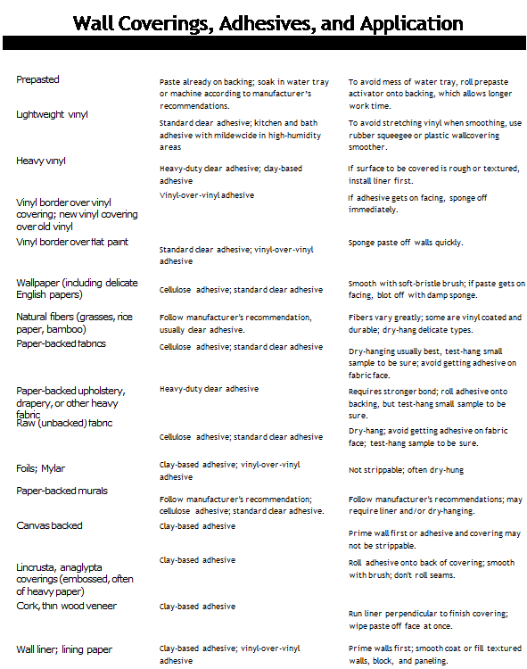
The wallcovering type determines which paste you need. Pastes come premixed, as shown, or as powders you mix with water. Many wallcoverings are prepasted and require that you either roll prepaste activator onto their backing or soak them in water trays.

How Much on a Roll?

Wallcovering rolls (also called bolts) are available in American single rolls, Euro rolls (metric), and commercial widths. At this writ­ing, Euro rolls dominate the market.

► American single rolls are 18 in. to 36 in. wide. (A 27-in. width is comfortable for most people.) The wider rolls generate fewer seams but are much more difficult to handle. Whatever the width of an American single roll, it will contain 36 sq. ft. of material.

► Euro rolls are 201/ in. to 28 in. wide, and are generally sold as double rolls (twice as long). Typically, there are 56 sq. ft. to 60 sq. ft. on a Euro roll.

► Commercial coverings are typically 48 in. to 54 in. wide, a width usually beyond the skills of nonprofessionals.

the square footage listed on the wallcovering rolls. If you’re using American single rolls (see "How Much on a Roll?,” below left), you could instead divide by 36 (the number of square feet on each roll). But dividing by 30 gives you an allowance for waste.

If the room has numerous recesses, difficult corners, or a lot of trim to cut around, order an extra roll or two. Also, if the pattern is large, you’ll waste more because you’ll need to match patterns along seams. On the back of most wall­covering, you’ll find the pattern repeat, usually stated in inches: The larger the pattern repeat, the greater the waste. Also, order an extra roll or two for repairs. You never know when a roof will leak or a child will bruise a wall.

Equipment

You’ll need some special tools and work surfaces to apply your wallcovering.

► A spirit level will tell you whether walls and wallcovering edges are plumb. Be sure to plumb the leading edge of the first strip of wallcovering. A 4-ft. level with metal edges can double as a straightedge when trimming selvage (manufactured edges).

► Your pasting table should have a washable top about 3 ft. by 6 ft. Avoid covering it with newspaper because newsprint may bleed. To protect the top from scarring during cutting, cover the tabletop with hardboard or use a zinc cutting-strip. (If you don’t have a suitable table, lay a sheet of smooth, void-free plywood over sawhorses.)

► Have a 16-ft. retractable tape measure for measuring and marking.

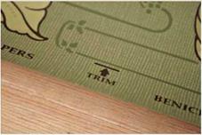
Подпись: PROTIP When you pick up your shipment of wallcovering, check the code number and run number on the label packed with each roll. Code numbers indicate pattern and color. Run numbers tell what dye lot you're getting. The dyes of different runs can vary considerably and will be especially noticeable side by side. So if you must accept different runs to complete a job, use the smaller quantity in a part of the room that isn't as conspicuous. Patterns tend to be current for at least 2 years. llll Подпись: LIFE ON THE Edge The edges of most wallcoverings are pretrimmed at the factory, allowing you simply to butt them after matching the patterns. If the edges aren't pretrimmed, do it yourself with a razor knife and long straightedge. Untrimmed edges are called selvage. Подпись: If the edges of a pretrimmed roll are frayed, refuse that roll. Similarly, refuse vinyls with edges that have become crimped in shipping or storage, for they cannot be rolled flat. To avoid damaging the edges yourself, always store the rolls flat—rather than on end.A razor knife with replaceable blades gives the cleanest cuts. Don’t be stingy about replacing blades during use because dull

image948

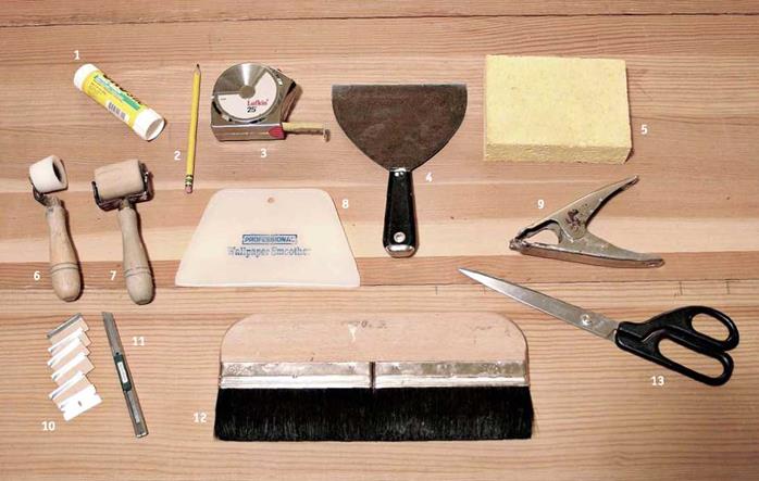
Подпись: Wallpapering tools. 1, Glue stick for touchups; 2, pencil; 3, tape measure; 4, 6-in. taping knife; 5, sponge; 6, beveled seam roller, used close to trim and in interior corners; 7, standard seam roller; 8, smoother- scraper; 9, spring clamp, to hold wallpaper while pasting; 10, singleedge razor blades; 11, razor knife with snap-off blades; 12, smoothing brush; 13, shears for rough-cutting strips. image949
blades can rip wallpaper. A professional may use 200 or 300 blades on a big job. Some pros prefer single-edge razor blades, though knives with snap-off blades are popular, too.

► Shears help you rough-cut from a roll.

► Paste brushes spread wheat paste on backing—or on walls, in some cases.

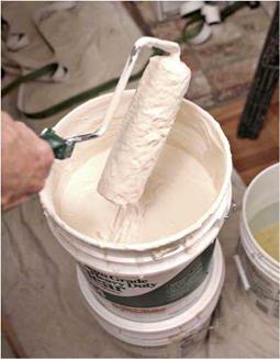
► A roller and pan are needed to spread vinyl paste, which is too heavy to brush on. Ask your supplier how long the nap of the roller cover should be.

► A smoothing brush, with soft bristles, will smooth out the wallcovering paste.

► A wallpaper smoother smooths vinyls, liners, and other heavy materials. It is also handy for flattening the occasional paste lump.

► A seam roller spreads glue along the edges of the strips to ensure that seams will stick well. Caution: Seam rollers are not generally recommended for delicate or finely textured papers or grasses.

► A 6-in. taping knife, also called a joint knife, is useful for filling low spots and scraping off high spots in a wall. Also use this knife to press the wallcovering snugly against the trim before cutting away excess paper.

► A sponge and water pail are handy for wiping excess paste off the pasting table, trim, and most wallcovering surfaces. In general, the sponge should be just damp. Change the water in your pail often. To avoid creating a sheen along the seams, wipe the entire strips rather than just their edges.

► Other useful equipment includes a sturdy fiberglass stepladder; a long, straight board for detecting irregularities in walls and ceilings; and a plenty of clean, soft rags. If you use a prepasted wallcovering, you’ll also need a water tray in which to soak the strips to activate their adhesives.

Soil Nailed Wall Facing Design Procedure

The following typical details and design procedure are based primarily on Caltrans’ method for use on highway construction, but the method is very similar to other methods presently in practice. Design facing pressures are based on the French Clouterre empirical method. The cast-in-place portion of the facing is designed for this pressure for permanent

FIGURE 8.57 Section through facing of soil nailed wall showing concrete reinforcement and soil nail connection. (From J. W. Keeley, Soil Nail Wall Facing: Sample Design Calculations, Federal Highway Administration, 1993, with permission)

walls only. The strength of the shotcrete construction facing is ignored. Only the ultimate limit state is addressed; no serviceability calculations are made for cracking or deflections. Sample design calculations are illustrated following the presentation of the procedure.

Typical Details. (See Figs. 8.57 to 8.59.)

1. Use a shotcrete layer with a 4-in (100-mm) minimum thickness.

2. Include a single layer of welded wire fabric at mid-thickness. Common options are:

6 X 6-W4.0 X W4.0 (4 gauge wire; diameter, 0.225 in; cross-section area = 0.080 in2/ft or 0.17 mm2/mm)

4 X 4-W2.9 X W2.9 (6 gauge wire; diameter, 0.192 in; cross-section area = 0.087 in2/ft or 0.18 mm2/mm)

3. Use two continuous horizontal no. 4 grade 60 reinforcing steel bars at each nail.

4. Use 1-ft-wide (300-mm) vertical geocomposite drain between nails; connect the geo­composite drain to a 2-in-round (600-mm) plastic weep hole outlet drain just above finished grade near the bottom of the wall.

5. Place the ASTM A36 steel nail bearing plate, 1 in X 9 in X 9 in (25 X 225 X 225 mm) with wedge washer and nut on the outside face of the shotcrete; set into place before the shotcrete hardens. Add studs to this plate to engage permanent facings that are placed over this initial shotcrete layer.

Step 1: 4-in (100-mm) Shotcrete Construction Facing. This is the only facing required for temporary walls (service life less than 18 months) and the first portion required for permanent walls. It is placed immediately after each stage of excavation and nail placement. Current AASHTO and American Concrete Institute (ACI) codes do not address the loadings or the structural capacities for this facing. Therefore, many current designs rely on details that have shown good performance on previous projects rather than design calculations.

Step 2: 8-in (200-mm) CIP Permanent Facing—Compute Design Nail Load and Pressure at Facing. The design nail load at the facing is computed for the given nail size, steel grade, and nail spacing according to the French Clouterre empirical method. The French determined through field tests that the nail load at the facing (T0) did not exceed about one-half the maximum nail load (T ) near the soil failure surface. They

v max

established a design nail load for the facing that varies from 0.6 times T for closely spaced nails to 1.0 times T for larger nail spacings. T is the ultimate limit state established for the nail tension (Caltrans procedure) at 0.75 X f (T = A. X 0.75 X

у v max nail

fy), where fy is the yield strength of the nail. The design pressure for the facing is then simply the design nail load at the facing (T0) divided by the nail tributary facing area (i. e., horizontal nail spacing times vertical nail spacing).

Step 3: 8-in CIP Permanent Facing—Design for Flexure. The cast-in-place facing is designed so that its ultimate strength is greater than the moments in the facing computed by simple continuous beam equations for the facing pressure from T0. Only one layer of grade 60 reinforcing steel placed near the middle of the section is used. (See Fig. 8.57.) The controlling d is used for the ultimate strength computation.

Step 4: 8-in CIP Permanent Facing—Nail Connection Design. The connection of the nail to the cast-in-place facing is designed to carry the nail’s ultimate limit state in tension, T. The nail bearing plate is sized to limit the bearing pressure from T to the

max max

ultimate value allowed by AASHTO (0.6f’c). The plate thickness is determined to provide sufficient bending strength for the moment from the bearing pressure about the nail nut. Studs are welded to the bearing plate to carry Tmax entirely by the 8-in (200-mm) CIP per­manent facing. The ultimate punching shear capacity of the steel embedment is computed according to American Concrete Institute specifications.

Sample Design Calculations for Soil Nail Wall Facing (Based on Caltrans Methods)

Step 1: 4-in Shotcrete Construction Facing. Details as previously described may be used.

Step 2: 8-in CIP Permanent Facing—Concrete Design Nail Load and Pressure at Facing. Given No. 8 nails; f = 60 kips/in2; Anail = 0.79 in2; horizontal nail spacing Sh = 6 ft; and vertical nail spacing Sv = 6 ft.

Begin by calculating the design nail loads.

T = design nail load at soil failure surface at ultimate limit state

max

= 0.75f A = 0.75 X 60 X 0.79 = 35.6 kips

у nail

T0 = design nail load at facing at ultimate limit state

(Note: This is the French Clouterre equation.)

The design nail load T0 is then used to calculate the facing design pressure.

Wu = facing design pressure at ultimate limit state

27.0

——- = 0.75 kip/ft2

6 X 6

Step 3: 8-in CIP Permanent Facing—Design for Flexure. Note: Try this wall section with No. 6 reinforcing bars spaced at 12 in horizontally and vertically; f c = 3250 lb/in2. c

Required ultimate moment per foot (horizontal and vertical; positive and negative)

Ultimate design capacity for trial section

8-in CIP permanent facing

depth of concrete compression

фмп=Фм(^ – _

= 0.9 X 0.44 X 60 X ^3.38 – __ j X _ = 5.9 ft • kips/ft > 2.7 OK

Check of minimum steel requirements. According to AASHTO, the tension rein­forcement must be equal to or greater than the lesser of that required to develop a moment (1) 1.2 times the cracking moment (based on the gross section modulus S ) and (2) 1.33 times that required by analysis for the specified loading conditions. This leads to the following equations for the cross-section area of the reinforcement:

1.2 X S X 7.5V2

_______ g_______ _

ф__ X 0.9d

The strength reduction factor ф is 0.90. Substitution gives the following results:

Thus, As must be at least 0.26 in2/ft to meet these requirements. For temperature and shrinkage, minimum As is 0.13 in2/ft (No. 4 @18 in). The final selection is No. 6 rein­forcing bars spaced at 12 in, which provides As of 0.44 in2/ft, a nominal level of reinforc­ing. For complete designs, also check cantilever sections at the top and bottom of the wall and any other special facing sections, such as at expansion or contraction joints.

Step 4: 8-in CIP Permanent Facing—Nail Connection Design

Design bearing plate at ultimate limit state for Tmax

T = 0.75f A = 0.75 X 60 X 0.79 = 35.6 kips

max y nail

Calculate the ultimate concrete bearing strength under the plate using a strength reduction factor of ф = 0.70. Therefore,

Ultimate concrete bearing strength = 0.85фf’c

= 0.60f’ .

c min

where w = ultimate bearing pressure.

Required steel area for studs to resist Tmax. The design strength of the stud fds is determined as the lesser of (1) the stud yield strength (f = 50 kips/in2) multiplied by a strength reduction factor of ф = 0.90 and (2) 80 percent of the stud tensile strength (fu = 60 kips/in2). Therefore,

fds = min Щ; 0.8fJ ф^ = 0.9 X 50 = 45 kips/in2

0. 8fu = 0.8 X 60 = 48 kips/in2

Therefore

fds = 45 kips/in2 T

Required stud area As = —

fds 35.6

Try 4/2-in ф studs.

As = 4 X 0.196 = 0.79 in2 OK

Check of anchor head bearing for ‘A-in ф stud. ds = 0.5 in. Determine head area Ah.

dh^2

Ah 0.79

A 0.196

T. = 0.312 in > 0.25 in

Head thickness is OK.

Ultimate connection embedment design capacity Pd Pd = 4ф VfA

d c cp

f’ = 3250 lb/in2

c

ф = 0.65 = strength reduction factor in this case
Acp = 291.7 in2 = effective stress area (see Fig. 8.59)

Pd = 4 X 0.65 X V3250 X 291.7 X = 43.2 kips

P, > T = 35.6 kips OK

d max

Stair

Stair

S

tairs do not really support or protect a building in the same way as foundations, floors, walls, and roofs, but this book would be incomplete without them. Stairs are the vertical connectors of the parts of the building. Most buildings require a few steps just to enter the main floor, and stairs connect any internal levels. A well-designed and well-built stair­case can contribute immeasurably to the function and beauty of a building.

STAIR DIMENSIONS

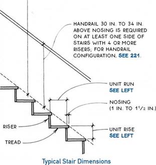
More than most other parts of a building, stairs need to be proportioned to the human body for safety. The height (rise) and depth (run) of the individual step must be in a comfortable relationship for the average person and must be manageable for people who are infirm or disabled. Building codes prescribe a range of dimen­sions for rise and run, a minimum width for stairways, the location of handrails, and minimum head clear­ance over stairs. The numbers vaiy depending on the location of the stair, the building type, and the specific code; the typical requirements are outlined as follows:

Rise and ШП— Rise and run of stairs are governed by building codes, which may vaiy. Minimum unit rise is typically 4 in. and maximum is 7 in., except for resi­dential stairs, which can have a unit rise of 73/4 in. For residential stairs, however, a comfortable rise is about 7 in. Minimum unit run is 11 in., except for residential stairs, which can have 10-in. treads.

Generally, deeper treads have shallower risers.

Flere are two useful rules of thumb for the rise/run relationship:

rise + run = 17 in. to 18 in.

run + twice the rise = 24 in. to 26 in.

Both for safety and for code compliance, it is impor­tant to make each riser of a stair the same height. Most codes allow only 3/8-in. variance between the tallest and shortest riser in a flight of stairs. The maximum total rise between floors or landings is typically 12 ft. Landings must be as deep as the width of the stairway but need not exceed 44 in. if the stair has a straight run.

Stair width— The width of stairways is also defined by building codes. Minimum width is usually 36 in. for residential stairs. Minimum widths are measured inside finished stair­wells, so rough openings must allow for finished wall surfaces.

HEADROOM is MEASURED VERTiCALLY FROM AN iMAGiNARY LiNE CONNECTiNG THE NOSiNG OF ALL TREADS;

MiNiMUM HEADROOM REQUiRED BY CODE iS TYPiCALLY 6 FT. 8 iN.

ALTHOUGH 7 Ft. is MORE Comfortable.

Stair

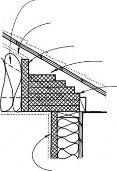
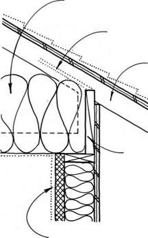
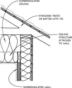
SUPERINSULATED CEILINGS

SUPERiNSULATED

CEiLiNG


SUPERiNSULATED

CEiLiNG


VENT cHANNEL FOR BLOwN-IN iNSULATiON


VENT CHANNEL FOR BLOWN-iN iNSULATiON


raised-heel

TRUSS SEE 198


RiGiD iNSULATiON BAFFLE


STANDARD TRUSS OR RAFTER WiTH TiE


RiGiD

iNSULATiON WiTH R-VALUE EQUAL TO CENTRAL pORTiON OF MAiN cEiLiNG


blocking between TRUSSES TO prevent ROTATION


SUpERiNSULATED wALL


SUpERiNSULATED wALL


SUPERINSULATED CEILINGSSUPERINSULATED CEILINGS

SUPERINSULATED CEILING

Rigid Insulation

SUPERINSULATED CEILING

Raised-Heel Truss

SUPERINSULATED CEILINGSSUPERINSULATED CEILINGS

SUPERINSULATED CEILING

Dropped Ceiling

SUPERINSULATED CEILING

Raised Plate

GABLE VENTS SEE 201


VENTiiNG AN ABUTTiNG ROOF SEE 150D. 204


SUPERINSULATED CEILINGS

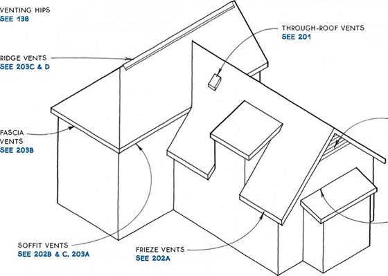
Roofs and attics must be vented to prevent heat buildup in summer and to help minimize condensa­tion in winter. (Condensation is reduced primarily by the installation of a vapor barrier, see 197.) In addition, winter ventilation is necessary in cold climates to pre­vent escaping heat from melting snow that can refreeze and cause structural or moisture damage.

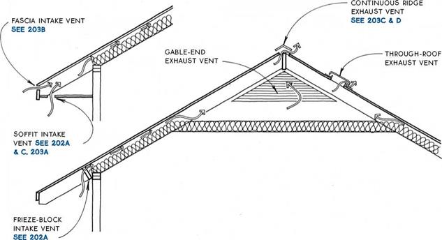
The best way to ventilate a roof or attic is with both low (intake) and high (exhaust) vents, which together create convection currents. Codes recognize this by allowing the ventilation area to be cut in half if vents are placed both high and low. Most codes allow the net free-ventilating area to be reduced from Уібо to У300 of the area vented if half of the vents are 3 ft. above the eave line, with the other half located at the eave line.

Passive ventilation using convection will suffice for almost every winter venting need, but active ventila­tion is preferred in some areas for the warm season. Electric-powered fan ventilators improve summer cooling by moving more air through the attic space
to remove the heat that has entered the attic space through the roof. The use of fans should be carefully coordinated with the intake and exhaust venting dis­cussed in this section so that the flow of air through the attic is maximized.

Some roofing materials (e. g., shakes, shingles, and tile) are self-venting if applied over open sheathing. These roof assemblies can provide significant ventila­tion directly through voids in the roof itself. Check with local building officials to verify the acceptance of this type of ventilation.

A special roof, called a cold roof (see 204A), is designed to ventilate vaulted ceilings in extremely cold climates. The cold roof prevents the formation of ice dams—formed when snow thawed by escaping heat refreezes at the eave. When an ice dam forms, thawed snow can pond behind it and eventually find its way into the structure. The cold roof prevents ice dams by using ventilation to isolate the snow from the heated space.

A R00F & ATTIC VENTING

SUPERINSULATED CEILINGS

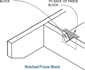
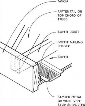
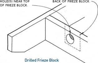
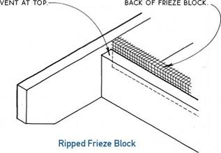
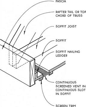
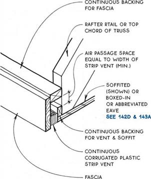
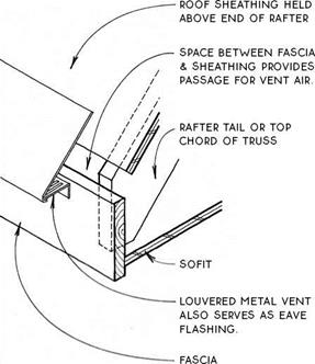
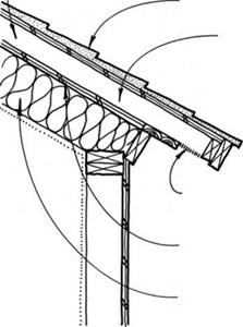
Intake vents—Intake vents are commonly located either in a frieze block or in a soffit or fascia. They are usually screened to keep out birds and insects. The screening itself impedes the flow of air, so the vent area should be increased to allow for the screen (by a factor of 1.25 for V8-in. mesh screen, 2.0 for //L6-in. screen). The net venting area of all intake vents together should equal about half of the total area of vents.

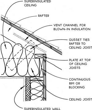
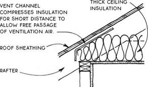
Vent channels may be applied to the underside of the roof sheathing in locations where the free flow of air from intake vents may be restricted by insulation. The vent channels provide an air space by holding the insulation away from the sheathing. These channels should be used only for short distances, such as at the edge of an insulated ceiling. For alternative solutions to this problem, see 198 & 199.

SUPERINSULATED CEILINGS

Exhaust vents—If appropriately sized and balanced with intake vents, exhaust vents should remove excess moisture in winter. There are three types of exhaust vents: the continuous ridge vent, the gable-end vent, and the through-roof exhaust vent.

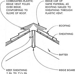
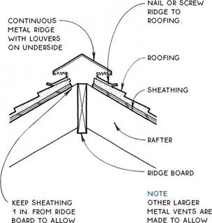
The continuous ridge vent is best for preventing summer heat buildup because it is located highest on the roof and theoretically draws ventilation air evenly across the entire underside of the roof surface. Ridge vents can be awkward looking, but they can also be fairly unobtrusive if detailed carefully (see 203C &

D). (Another type of ridge vent, the cupola, is also an effective ventilator, but is difficult to waterproof against wind-driven rain.)

The gable-end vent is a reasonably economical exhaust vent. Gable-end vents should be located across the attic space from one another. They are readily avail­able in metal, vinyl, or wood, and in round, rectangular or triangular shapes. Because the shape of gable-end vents can be visually dominant, they may be empha­sized as a design feature of the building.

The through-roof exhaust vent is available as the “cake pan" type illustrated above or the larger rotating turbine type, available in many sizes. Through-roof vents are usually shingled into the roof and are useful for areas difficult to vent with a continuous ridge vent or a gable-end vent.

NOTCH TOP OF FRiEZE FOLD SCREEN & STAPLE

SUPERINSULATED CEILINGS


RiP FRiEZE BLOCK TO FOLD SCREEN, PRESS UP

ALLOW CONTiNUOUS TO SHEATHiNG & STAPLE TO


SUPERINSULATED CEILINGS

В


SUPERINSULATED CEILINGS

by SOFFiT


BORE ROuND VENT Staple SCREEN TO

SUPERINSULATED CEILINGS


FRIEZE-BLOCK INTAKE VENTS

Three Types


SOFFIT INTAKE VENT

Stamped


SUPERINSULATED CEILINGSSUPERINSULATED CEILINGSSUPERINSULATED CEILINGS

SUPERINSULATED CEILINGS

SUPERINSULATED CEILINGSSUPERINSULATED CEILINGS

SUPERINSULATED CEILINGS

SOFFIT INAKE VENT

Corrugated Strip

FASCIA INTAKE VENT

Starter

SUPERINSULATED CEILINGS

FROM RIDGE BOARD TO ALLOW FREE AIR pASSAGE.


SUPERINSULATED CEILINGS

FREE AIR PASSAGE. SHiNGLiNG-OVER

OF VENT FOR APPEARANCE.


RIDGE EXHAUST VENT

RIDGE EXHAUST VENT

AIR CHANNEL CONTiNUOUS TO VENT(S)

AT TOP OF ROOF. VENTS MUST HAVE AREA EQUAL TO SOFFIT VENTS AND NOT BE SUSCEPTIBLE TO CLOGGING ВУ SNOW.


ROOFING


2×4 sleepers aligned with

RAFTERS pROViDE

continuous AIR cHANNEL FOR VENTILATION.


31/2-in. continuous ScREENED SOFFIT VENT


CONTINUOUS SHEATHING COVERED WITH 30-LB. FELT


NOTE

INSULATION

can be batts

W/VENTED AIR Space OR RIGID INSULATION THAT FILLS cAVITy.


INSULATION BETWEEN RAFTERS WITH VAPOR BARRIER ON WARM SIDE BELOW


SUPERINSULATED CEILINGSSUPERINSULATED CEILINGS

The cold roof is a way to protect vaulted ceilings in cold climates from the formation of ice dams. A cold roof is a double-layer roof with the upper layer vented and the lower layer insulated. The vented layer promotes continuous unrestricted air flow from eave to ridge across the entire area of the roof. This flow of cold air removes any heat that escapes through the insulated layer below. The entire outer roof surface is thus maintained at the temperature of the ambient air, thereby preventing the freeze-thaw cycle caused by heat escaping through the insulation of conventional roofs.

The typical cold roof is built with sleepers aligned over rafters and with continuous eave vents and comple­mentary ridge or gable vents. A 3f/2-in. air space has been found to provide adequate ventilation, but a іУг-т. air space does not. The sleepers must be held away from obstructions such as skylights, vents, hips, and valleys to allow air to flow continuously around them.

A modified cold roof with extra-deep rafters to pro­vide deeper than normal ventilation space but without the double-layer ventilation system can also work.

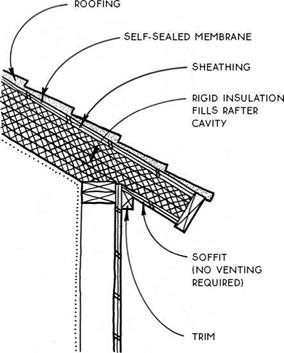
The warm roof also protects vaulted ceilings in cold climates from the formation of ice dams. Instead of isolating the snow from the insulation like a cold roof however, the warm roof prevents escaping heat from melting the snow by increasing insulation thickness. When the ceiling R-value is sufficient (approximately R-50 is recommended), the temperature on the surface of the roof can be maintained at the temperature of the snow. The snow will therefore not melt while the ambient temperature remains below freezing.

By using rigid insulation, the warm roof eliminates the ventilation space because there are no voids within which condensation can form, so there is no need to ventilate between the insulation and the roof surface. With snow effectively adjacent to the insulation, the insulative value of the snow itself will contribute to the insulation of the building. In this respect, the warm roof is superior to the cold roof because the cold roof exposes the outer surface of the insulation to ambient air (which can be significantly colder than snow).

When compared to the cold roof, the warm roof is less complicated to build and will insulate better. It is made with expensive materials, however, so may have a higher first cost—especially for owner-builders.

Подпись: WARM ROOFA cold roqf

Flat roofs, like sloped roofs, require ventilation to prevent heat buildup and to minimize condensation. The principles of ventilation are the same for flat roofs as for sloped roofs, but flat roofs have some particular ventilation requirements due to their shape. On a flat roof, a low intake vent can rarely be balanced by a high exhaust vent (3 ft. min. above the intake vent). The
net free-ventilating area therefore cannot usually be reduced from кІ50 of the area of the roof.

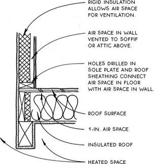
Flat-roof ventilators are commonly of the continuous strip type, located at a soffit, or a series of small vents scattered across the roof. Parapet walls can also provide effective ventilation for flat roofs (see 205B).

ROOF VENT ABOVE VENT iN PARAPET WALL

SUPERINSULATED CEILINGS


FLAT-ROOF VENTING

SUPERINSULATED CEILINGS

NOTE

seal carefully between framing members

AND RIGID iNSuLATiON TO PREVENT AiR INFILTRATION.


CAP FLASHiNG

WALL VENTS AS REQUiRED

PARAPET WALL

BLOCKING ALLOWS SPACE FOR AiR PASSAGE

cant strip

ROOF SuRFAcE

1-IN. AiR SPAcE required

Insulated ROOF

heated space


NOTE

IT MAY Be uSEFuL TO Be Able TO VENT AN iNSuLATED ROOF (OR DEOO THROuGH A PARAPET wALL IN ORDER TO GET cROSS VENTILATION.


SUPERINSULATED CEILINGS

VENTED PARAPET WALL

European Standards Concerning SMA

A series of European standards—designated EN 13108 and containing requirements for the design, testing, and production of asphalt mixtures—has been implemented in all member states of the European Committee for Standardization (CEN). It consists of 10 standards:

Подпись: 1. 2. 3. 4. 5. 6. 7. 3. 9. 10. Подпись: -Material Specifications—Part 1: -Material Specifications—Part 2: -Material Specifications—Part 3: -Material Specifications—Part 4: -Material Specifications—Part 5: -Material Specifications—Part 6: -Material Specifications—Part 7: Material Specifications—Part 8: -Material Specifications—Part 20: -Material Specifications—Part 21:EN 13108-1:2006, Bituminous Mixtures— Asphalt Concrete

EN 13108-2:2006, Bituminous Mixtures— Asphalt Concrete for Very Thin Layers EN 13108-3:2006, Bituminous Mixtures – Soft Asphalt

EN 13108-4:2006, Bituminous Mixtures – Hot Rolled Asphalt

EN 13108-5:2006, Bituminous Mixtures – Stone Mastic Asphalt EN 13108-6:2006, Bituminous Mixtures – Mastic Asphalt

EN 13108-7:2006, Bituminous Mixtures – Porous Asphalt

EN 13108-8:2005, Bituminous Mixtures – Reclaimed Asphalt

EN 13108-20:2006, Bituminous Mixtures – Type Testing

EN 13108-21:2006, Bituminous Mixtures – Factory Production Control

The standards numbered from 1 to 7 are intended for constructing products harmo­nized with the Construction Product Directive No. 89/106, which is a classification type of standard. This type of standard does not include ready-to-meet sets of require­ments, but only a list of properties with a set of categories-levels of requirements. Basically, they are universal standards to be adopted by any CEN-member state.

It is impossible to establish the same requirements for all of Europe due to its substantial climatic differences and diversified road technology experiences. As a result, the common standard has to reflect these differences. The crucial point is that all countries use the same category symbols for SMA properties and the same testing methods for those mixtures. Owing to this classification standard, each country may individually specify its essential requirements for asphalt mixtures by placing them
in a national application document (NAD). The NAD is understood to be a document introducing an EN standard in national technical regulations, containing a combina­tion of properties and levels of requirements suitable for a given country. An NAD may appear in one of the following form of:

• Technical guidelines (e. g., British PD 6691)

• A national standard that does not contradict the EN standard (e. g., Austrian standard ONORM B 3584:2006)

• A National Annex to a national standard implementing the EN standard (e. g., Slovenian Standard SIST 13108-5)

Apart from the standards concerning separate asphalt mixtures (numbered from 1 to 7), the system contains three additional standards (numbered 8, 20, and 21). The standard EN 13108-8 applies to reclaimed asphalt (RAP), therefore it does not refer to a construction product directive. The standard EN 13108-20, entitled Type Testing, concerns the required range of tests necessary for marking a mixture with the CE symbol (for so-called conformity assessment). The last standard, EN 13108-21 Factory Production Control, includes the description of requirements for asphalt plants and quality control. All parts form a complete system of require­ments for design, testing, production, and the conformity assessment of asphalt mixtures.

The standard EN 13108-5, which describes the classification system of require­ments for SMA mixtures, will be further discussed. Subsequently, the clauses of EN 13108-20 concerning SMA mixtures will be outlined. The present chapter con­cludes with a description of factory production control according to the standard EN 13108-21.

Any reader interested in details of the presented standards should look at the original texts and clauses.

APPLYING EXTERIOR PAINT

Prep work done, it’s almost time to paint. Even if you’ve read this entire chapter, you might want to scan it one last time for tips about paint quality, tools, basic techniques, spray-painting, and so on.

Here’s a quick review of factors mentioned in greater detail earlier in this chapter: Regarding exterior coatings, the more opaque the finish, the better it will protect wood siding. Clear, oil-based sealers help siding shed water without obscuring the wood grain, but they must to be reapplied every 2 years to 4 years because they offer rela­tively little protection from UV rays. A second
Подпись:Подпись: llllimage938

option, semitransparent stains resemble thinned down-paints and represent a compromise that adds UV protection but reduces siding visibility, That is, you can see wood texture but not its grain. Third, there’s paint that completely hides and so protects wood the best, if correctly applied. Which brings us to acrylic latex.

Acrylic latex is king. What’s not to like? Simply called latex, it’s durable, flexible, virtually odor­less, and cleans up with soap and water. Use good-quality latex primer-sealer and paint on all exteriors, whether covering existing paint or unfinished siding. Oil-based primers are justified only if your siding is raw redwood or cedar, or if you’ve had problems with tannin bleed-through and so need to block stains before repainting. Latex is also best for masonry, stucco, aluminum, and vinyl siding because it’s the only coating flex­ible enough to expand and contract as siding heats and cools.

Optimal conditions. Check the weather before you start painting. Ideally, wait until several dry days are forecast. If possible, wait a week after a rain. Also allow morning mists to evaporate before painting. Humidity near 90 is risky, because it doesn’t allow the paint to cure. The best temperatures for curing range between 60°F and 85°F. Don’t paint when temperatures are 90°F or above, because surfaces that are too hot can cause paint to blister. Finally, stop painting 2 hours before sundown if nighttime tempera­tures could drop below 40°F.

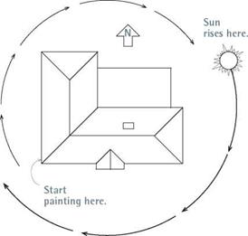
If possible, don’t paint in strong sun. Paint the west and south faces of the house early in the morning; the north face at noon; and the east face and any part of the south face still remaining in the afternoon.

Latex paint should flow on easily and dry slowly enough that brush marks level (disappear). To slow the rate of drying, add a dash of Flood’s Floetrol to latex, as indicated on the container.

To slow the rate of drying of oil-based paint, add Flood’s Penetrol.

A painting sequence. Paint the house from top to bottom. To minimize overlap marks on clap­boards, paint horizontal sections all the way across, till they end at window or door trim or at the end of a wall. After painting large sections, go back and paint the trim, windows, and doors, top to bottom. Last, paint gutters, porches, and decks. If you can remove shutters, doors, screens, and the like, do so; they are much easier to paint if placed across sawhorses. Don’t bother to mask trim or windows unless you’re spray-painting. Again, you can later scrap stray paint from win­dow glass with a razor tool.

Using a brush, paint the bottom edges of hori­zontal siding before applying paint to the flat face of each board. To distribute paint evenly along siding, after loading the brush with fresh paint, partially unload the brush by dabbing every foot or so; then spread out the dabs, brush­ing the paint in and smoothing it with the wood grain. For exteriors, a 4-in. brush is the work­horse for the big spaces. A 3-in. angled sash brush is handy for cutting in trim edges and corners. For a sequence of painting window parts, see p. 450.

If the house has a stucco exterior or some other flat expanse, roll the paint on—after using a brush to cut in the edges—or spray it. Exterior rolling is much the same as interior rolling: Roll on fat paint in a zigzag pattern, before rolling it out evenly. To minimize spatter, roll the first stroke up. In general, the smoother the exterior surface, the shorter the roller cover nap.

Apply primers and top coats full strength,

except when the paint seems to be drying too quickly. Latex dries quickly and adheres well, so you don’t need to sand between coats unless you wait several days or more. Consult the label on the paint container for drying times and maxi­mum intervals between coats. For a lasting paint job, apply one coat of primer and at least two top coats. Though it’s probably not imperative to

I Avoiding Direct Sun

Avoid the sun around the house as you paint, so that you apply paint in the shade if possible. Paint applied in full sunlight is more likely to blister later.

image939prime existing paint that’s in good shape and well prepped, it’s advisable. However, prime all siding that has been sanded or begun weathering down to bare wood.

Oil-based stains and semitransparent stains do not need thinning. Apply them full strength to bare wood. If you’ve stripped the house of its original paint and want to switch to stain, test a
small section first. Because a clear stain will probably look uneven, a semitransparent stain is likely the better bet. To apply stain, a paint pad will hold more stain than a brush but requires a little practice to avoid runs.

As with paint, apply stain to the undersides of the shingle or clapboard courses first. To avoid getting stain on your skin, wear a long-sleeved shirt, rubber gloves, a hat, and safety glasses.
Подпись: Use a cardboard shield to prevent overspray onto adjacent areas. Подпись: OF TIPS

Spray

► Spray exterior trim first. Mask the siding, spray the trim, and let it dry before removing the first masking. Then mask over (cover) the trim so you can paint the siding.

► To mask-off windows, apply double-sided masking tape around the perimeter of the window. Press sheet plastic to the tape and trim off the excess plastic.

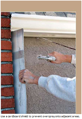
► To keep paint off features such as chimneys and roofing, use a cardboard shield to block the spray, as shown at left.

► Don’t spray when it’s windy. Even if the air is calm, move cars and lawn furniture away from the house, or cover them. If your house is close to a neighbor’s—ask the neighbors to do the same or, better, do it for them.

► After you spray a section, immediately brush the paint into the surface. Back-brushing helps sprayed paint adhere better, look great, and last longer.

But because latex dries so quickly, back-brush before spraying the next section.

After spraying a section of siding, immediately brush the paint into the wood—and into the building seams— using a 4-in. brush.
Подпись: Wallpapering

image942

Wallpaper has been popular for centuries, particularly in formal rooms where there’s less danger from little ones’ grimy fingers and rowdy ways. Paint has long been favored for rooms that get the most use and abuse because it’s durable and easy to clean and apply.

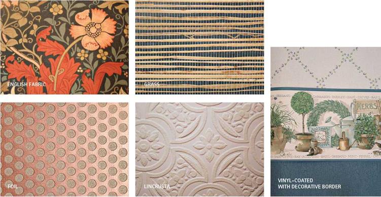
Today “wallpapers” are available in so many materials—including grasses, bamboo, rice paper, foil, and cork—that they are collectively called wallcoverings, and some of them are stronger, more durable, and easier to maintain than wallpapers and some paints. Many are backed with paper or cloth, with cloth being stronger. But by far the most popular are vinyl- coated wallcoverings, which are washable and grease resistant.

Today, most wallcoverings come prepasted. This makes them easier to apply and—years later—to strip from the wall. Because the manu­facturer has already pasted the covering, all you need do is unroll it, and soak it briefly in a water tray. But, as you’ll see in this chapter, many pros avoid the drips and mess of a water tray by rolling a prepaste activator onto the backing.

Selecting Materials

Choose a wallcovering whose pattern and color are appropriate for the room. There are no hard and fast rules on what works. But in general, lighter colors make rooms look larger, and darker colors make rooms look smaller. Smaller, sub­dued patterns are better for quiet rooms. Splashy floral prints tend to serve better in places such as front halls that bustle with activity. Delicate tex­tiles or grasses are best reserved for rooms with little traffic and little risk of bruising. Also, con­sider the age and energy level of the people in the room. For example, vinyl-coated murals of rock stars or sports themes will appeal to kids and endure abuse.

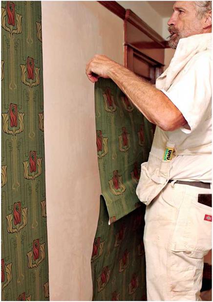
To hang wallcovering, first unfold the top half of a pasted strip and carefully align it to a plumbed line, or to the plumbed edge of the preceding strip.

Washable wallcoverings can be sponged clean occasionally with a mild soap or cleaning solu­tion. Scrubbable coverings can take a vigorous scouring with a nylon-bristled brush or a pad, as well as stronger cleaning agents. There are also strippable and peelable wallcoverings, discussed

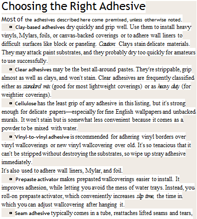
Подпись: g OVER DIFFERENCESimage943Подпись: Almost everybody still refers to wallcovering as 'wallpaper.' But in this chapter wallcovering, the noun, will be the general term for both paper and nonpaper coverings. However, when used as a verb, wallpaper refers to the act of hanging either type of covering. Last, you can assume that advice on papering or prep- ping walls also holds true for ceilings.Подпись: Choosing the Right Adhesive Most of the adhesives described here come premixed, unless otherwise noted. ► Clay-based adhesives dry quickly and grip well. Use them to install heavy vinyls, Mylars, foils, or canvas-backed coverings or to adhere wall liners to difficult surfaces like block or paneling. Caution: Clays stain delicate materials. They may attack paint substrates, and they probably dry too quickly for amateurs to use successfully. ► Clear adhesives may be the best all-around pastes. They're strippable, grip almost as well as clays, and won't stain. Clear adhesives are frequently classified either as standard mix (good for most lightweight coverings) or as heavy duty (for weightier coverings). ► Cellulose has the least grip of any adhesive in this listing, but it's strong enough for delicate papers—especially for fine English wallpapers and unbacked murals. It won't stain but is somewhat less convenient because it comes as a powder to be mixed with water. ► Vinyl-to-vinyl adhesive is recommended for adhering vinyl borders over vinyl wallcoverings or new vinyl wallcovering over old. It's so tenacious that it can't be stripped without destroying the substrates, so wipe up stray adhesive immediately. It's also used to adhere wall liners, Mylar, and foil. ► Prepaste activator makes prepasted wallcoverings easier to install. It improves adhesion, while letting you avoid the mess of water trays. Instead, you roll-on prepaste activator, which conveniently increases slip time, the time in which you can adjust wallcovering after hanging it. ► Seam adhesive typically comes in a tube, reattaches lifted seams and tears, and is compatible with all wallcoverings. After applying seam adhesive, roll the seam.

at greater length in “Stripping Wallpaper,” on p. 470.

For do-it-yourselfers, it’s smart to choose a covering that’s easy to hang. That is, textured coverings can be fragile and difficult to handle. The condition of existing walls should also affect your decision. For example, heavy coverings can conceal minor wall flaws; whereas lightweight papers will accentuate flaws and won’t conceal underlying bold paints or vivid patterns. If walls or trim are badly out of square, avoid coverings with large, bold patterns because slight mis­matches along their edges will be more obvious than if patterns are subdued.

Measure and cut the casing

Often referred to as door and window trim, cas­ing hides the joint between the drywall and the door or window jamb. Spend some time at your local lumberyard and you’ll see all the styles and grades of casing, including the type that’s installed at the factory on many prehung doors. Solid wood casing can be used if you want to leave the wood natural. Paint-grade trim— made from MDF or from shorter pieces of wood that have been finger-jointed together—is also available and costs less. Some people prefer a plain, narrow, simple style, whereas others prefer wider, more complex profiles. Purchase 14-ft. lengths to minimize waste. Another option is to buy 7-ft.-long pieces that have a 45-degree miter precut on one end. These pieces are used to trim around doors.

PLAN FOR A REVEAL. When running casing, carpenters commonly leave what’s called a reveal, which simply means that one piece of wood is held back a bit so you can see the edge of the piece beneath it. The idea is to create a shadow line, which produces a sense of depth and adds visual interest. This is done even on simple trim in an affordable house. To mark the setback for the casing on the jamb, use an adjustable combination square. Set it at about 3/i6 in. to /4 in. in from the inside edge of the jamb—whether it is on a door, a window, or an attic access—and mark a pencil line in several places (see the illus­tration at right). With a little experience, you’ll be able to mark a setback by eye, without a square. The casing is cut and nailed to that line.

MARK AND CUT THE CASING. Now it’s time to cut the side and head casings to length. Cut and nail the casing with its thinner edge facing in, toward the door opening. The baseboard trim butts into the wide edge of the casing at the floor line. To find the length of a piece of side-jamb casing, measure from the floor to the horizontal reveal line at the top of the door or window. That measurement is the distance to the short point of the miter cut.

Another way to obtain this measurement is to hold a piece of casing alongside the door or
across the head jamb and mark the short end of the miter cut at the /4-in. reveal line (see the bottom left photo on p. 252). Make a diagonal mark on the casing to show which way to make the cut. Just make sure the mark will be cut off, so it won’t be visible once the casing is installed. Take the casing stock to the chopsaw and make the cut. Side casings are cut in pairs, one for the jamb on the right and one for the jamb on the left. Take your time. Work slowly. Make sure you are cutting in pairs.

The same technique can be used for win­dows with sills and jambs. Measure from the sill to the horizontal reveal on the head jamb (for side casings) and from one vertical reveal line to the other on the side jambs (for head casings). All these marks are made from heel to heel, or short point to short point, of the miter cut.

Подпись:In theory, once you know the length of one piece of casing, you should be able to set up

Hand-nail trim with care. When using a hammer to attach trim to the wall, leave the finish nail about [3]/8 in. proud of (higher than) the surface of the wood, then use a nail set to drive it about Уг in. below the sur­face. The hole will be filled with putty and sanded prior to painting. Take care not to miss the nail and leave a hammer track in the wood surface.

at the saw and cut every piece for doors and windows of the same size. This can eliminate repetitive measuring and lots of time spent walking back and forth to your saw. In practice, side casings may vary slightly in length. But small gaps at the floor line will be hidden by carpeting or cut to uniform distance to accom­modate wood or other finish flooring. Find out what carpenters are doing in your area.

Joisting Tips

Material Movement for Joists

1. Material movement is a major part of installing joists.

2. Always carry the joists crown-up. This way, you can spread the joists in place, in the right direction, without having to look for the crown a second time. It’s easier to look for the crown on the lumber pile than when it is on the wall.

3. Check on the size of joists and positions needed. Try to spread the joists on the top of the pile first so you won’t have to restack them.

4. Check your carrying path for the joists. Sometimes you can reduce your overall time by making a simple ramp or laying a joist perpendicular to those already in place.


Cutting Joists to Length

1. Cut joists after spreading.

• Spread joists on layout, and tight to rim joists.

• Chalk cut line.

• Lift and cut each joist in sequence.

2. Cut joist on lumber stack.

• Measure joist lengths.

• Cut multiple joists on lumber pile.

Nailing Joists

1. Position joist on layout and plumb.

2. Nail through rim joist into joists, making sure joist is plumb.

3. Toenail through joist into double plate. Nail away from end of joist to prevent splitting.

Rafter Tips

Cutting Rafters

1. Figure cut lines for rafters, and check measurements before cutting.

2. Install common rafters first.

3. Cut three rafters.

4. Check two to see if they fit. If they fit, leave them in place and use the third as a pattern for remaining cuts. If they don’t fit, cut to fit or save for hip or valley jacks.

5. Cut balance of common rafters and install.

Installing Ridge Board

1. Figure height for ridge board.

2. Install temporary supports for the ridge board.

3. Install ridge board.

Nailing Rafters

1. Toenail common rafters on layout into double plate.

2. Nail on layout through ridge board into rafter.

3. Cut hip and valley rafters.

4. Cut jack rafters.

5. Set and nail hip or valley rafter.

6. String line centerline of hip or valley.

7. Layout hip or valley rafter.

8. Toenail jack rafter on layout through rafter into double plate.

9. Nail jack rafter to hip or valley rafter.

Sheathing Tips

Floor Sheathing

1. Make sure the first piece goes on square.

2. Chalk a line using a reference line and the longest part of the building possible.

3. Align the short edge of the plywood with interior joists, the long edge with the rim.

4. Pull the layout from secured interior joists.

5. Nail the plywood to align with the chalk line and layout marks.

Water Quality Improvement

The slow percolation of contaminated runoff into the pavement through a porous aggregate layer to an outlet substantially slows water movements, provides the possibility of filtration and allows water to pass by a large surface area of stone. By these means the water drops the suspended, fine, solids that it is carrying into the pore space of the pavement layers. The contaminants tend to adhere to the surfaces of the porous material’s particles – particularly to the fine fraction as it provides the largest area of fines. Hydrocarbon contaminants also tend to be sorbed to the solids. For these reasons the water that leaves the pavement is substantially

Hardness

Conductivity

Copper

Zinc

Motor oil

(mg CaCO3)

(pmhos/cm)

(Pg/l)

(Pg/l)

(mg/l)

Infiltration

Table 13.3 Mean concentrations of detected constituents in water running off or through 5 exper­imental pavements (from Brattebo & Booth, 2002)

Plastic grid filled with sand. Grassed

23.4

48

1.29 (6)

10.8(2)

<detection

Plastic grid filled with sand

14.7

38

<detection

14.3

<detection

60% open concrete blocks filled with gravel. Grassed

47.6

114

1.88(4)

12.2 (3)

<detection

90% solid concrete with gravel

49.8

Surface run-off

113

1.7(7)

8.6 (3)

<detection

Asphalt

7.91

14.1

9.07

22.2

0.183(1)

The water from 9 storms was measured. The number in parentheses indicates the number of sam­ples in which contamination was at less than the detection limit.