Stair configuration

The shape or configuration of a stairway is determined primarily by the circulation patterns of a building and by available space. Virtually any configuration of stairway may be constructed using the standard details of this chapter by merely breaking the stairway into smaller pieces and reassembling them. Several typical configurations that are worthy of note are shown in the drawings that follow; for clarity, these drawings do not show railings.

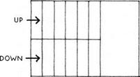
Straight-run stair—The straight-run stair is the most economical standard stairway from the stand­point of efficiency of floor space taken up by the stairway itself. The straight-run stair works best in two-story buildings.

Stair configuration

The bottom and top steps are separated horizontally from each other by the entire length of the stairway, so that a multistory building with stacked stairways requires circulation space on each floor to get from the top step of one flight to the bottom step of the next.

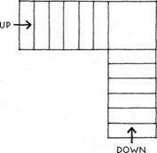
U-Shaped Stair— The U-shaped stair, also called a switchback stair, has a landing about half a flight up, and the flights run in opposite directions. The area of the stairway is increased over a straight-run stair by the area of the landing (less one step), but the top step of one flight is adjacent to the bottom step of the next. This arrangement saves circulation space at each floor level and makes this stair more efficient overall for multistory buildings than the straight-run stair.

Stair configuration

L-Shaped stair—The L-shaped stair is not so common as the straight or U-shaped stair because it lacks the simplicity of the straight-run stair and the efficiency of the U-shaped stair. It can, however, be useful in tight spots, as it takes up less floor space than a U-shaped stair and requires less length than a straight-run stair. The framing of the opening in the floor for this stairway can be atypical because of its L-shape. A framed wall under one side of the floor projecting into the L or a column under the floor at the bend in the L is the most common way to support this floor.

Stair configuration

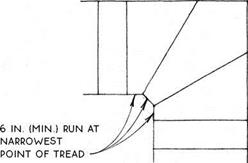
Winder stairs at the bend in the L (or at the bend in a U-shaped stair) are common, but for reasons of safety, should not be allowed to be less than 6 in. deep at the narrow end (verify with local codes).

Stair configuration

Spiral Stair – A spiral stair saves space. It is most appropriate for accessing mezzanines and lofts where furniture and other large items may actually be hoisted from floor to floor by means other than the stairway. Spiral stairs usually have special code requirements that are somewhat less restrictive than standard stairs. They are usually prefabricated, often of metal or wood kits. Their details are idiosyncratic and not included in this book.

Install the base cabinets in kitchens and baths

Cabinet installation details are the same, whether you’re working in the kitchen, the bathroom, or any room. Some people prefer to install wall cabinets first so they won’t have to reach over the base cabinets. Perhaps
because 1 am tall, I generally install base cabi­nets first. Either way, it’s best to begin in a corner. Corner cabinets tend to be large and are trickier to install because they have to fit against two wall surfaces. But once you get a corner cabinet installed plumb and level, you’ll have an easier time with the rest of the job.

PLANNING AND PREPARATION ARE IMPOR­TANT. Before you screw any cabinets to the wall, it’s a good idea to line them up and see whether they will fit into the allotted space.

It’s not unheard of for one or more cabinets to be manufactured in the wrong size, so this test-fitting exercise is important. At this stage, and during the installation process, it’s impor­tant to allow adequate clearances between cabinets for the major appliances. For exam­ple, you should leave between 30% in. and 30% in. of space between base cabinets to fit a standard 30-in.-wide range or stove. Your final prep step is to label all cabinet doors and drawers, then remove them until you’ve fin – ished the installation process.

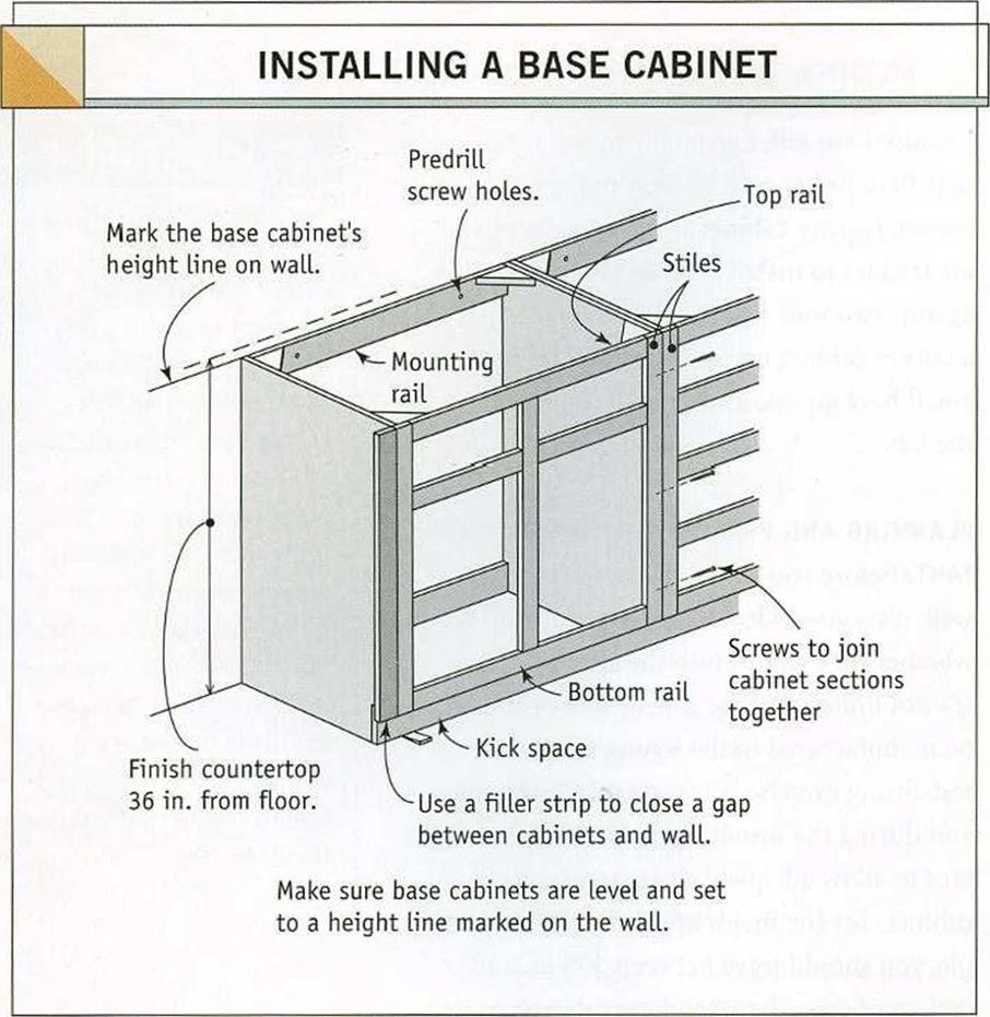
START WITH A LEVEL LINE. Begin the installa­tion process by marking a level line on the wall, where the top edges of your base cabinets will fit. If you suspect that the floor surface isn’t exactly level where the cabinets will be

Install the base cabinets in kitchens and bathsinstalled, use a level to find the highest spot on the floor, then measure up the wall near that spot. The standard height of base cabinets without a countertop is usually 34/ in. or 35/ in., depending on the manufacturer (see the illustration above).

DRIVE INSTALLATION SCREWS INTO STUDS.

Base cabinets are screwed into wall studs or the 2×4 backing described in chapter 4. If stud locations were not marked on the floor, you can locate them by tapping lightly on the dry- wall with a hammer and listening for a solid sound. To make sure you’ve found a stud, drive a nail through the drywall in a place where the cabinet will cover the holes. Once you locate one stud, other studs should be 16 in. or 24 in. o. c. Use З-in. flat-head screws to install cabinets. Don’t use drywall screws, because they tend to be brittle and aren’t designed to support heavy loads.

GET CABINETS LEVEL. Make sure the top back edge of the cabinet sets directly to the wall line so it’s level. Predrill holes for the installation screws through the mounting rail and into the studs. Then screw the cabinet to the wall. Now place a 2-ft. level across the top of the cabinet from the back edge to the front edge. As nec­essary, wedge shims under the cabinet to get the top of the cabinet level in all directions. You can glue the shims in place to make sure they don’t shift around. If any part of a shim projects beyond the front or side of a cabinet, cut or chisel it flush. Use this leveling tech­nique when installing all base cabinets.

JOIN CABINETS TOGETHER. Separate cabinets, both base and wall types, are joined together where their stiles meet. A stile is a vertical member in the rectangular face frame that forms the front of most cabinets. Horizontal frame members are called rails (see the illus­tration at left). If the cabinets are European- style frameless ones, join them together by screwing the sides to each other. With face – frame cabinets, the stiles of adjacent cabinets are clamped together, drilled, and screwed.

As you join and clamp one cabinet to another, make sure each cabinet is level and at the proper height. A pair of clamps should be sufficient to hold two stiles together until you screw them to each other. Drill countersunk pilot holes for two screws, one near the top hinge and one near the bottom hinge. A third screw can be driven near the center of the stile, if necessary. With a countersunk pilot hole, the head of the screw should be just slightly below the wood surface.

CUT HOLES IN SINK CABINETS. A base cabi­net that will hold a sink needs to have holes drilled or cut at the back for water supply and waste lines. A kitchen sink base will also have an electrical line coming in, if a garbage

Install the base cabinets in kitchens and baths
Install the base cabinets in kitchens and bathsMAKE ROOM FOR UTILITIES BENEATH THE SINK. Holes must be drilled in the back of sink cabinets to make room for pipes and elec­trical wires.

disposal unit and/or a dishwasher will be installed (see the photo above). Measure from the floor and the adjoining cabinet to locate the centers of the access holes. You can use a jigsaw or a drill with a hole saw to cut the holes. Drill slowly and leave a neat-looking job. Seal any holes around pipes with expand­ing foam or caulk.

FILL GAPS WITH STRIPS. At times, you may need a vertical filler strip to close a gap between the edge of a cabinet and an adjoin­ing wall. A filler strip is like a stile. It is cut to the width of the gap and then screwed to the cabinet stile, as shown in the illustration on the facing page. If the space allotted between walls is too small for the cabinets to fit in, the overhanging part of a stile can often be trimmed to make more room.

Install the wall cabinets

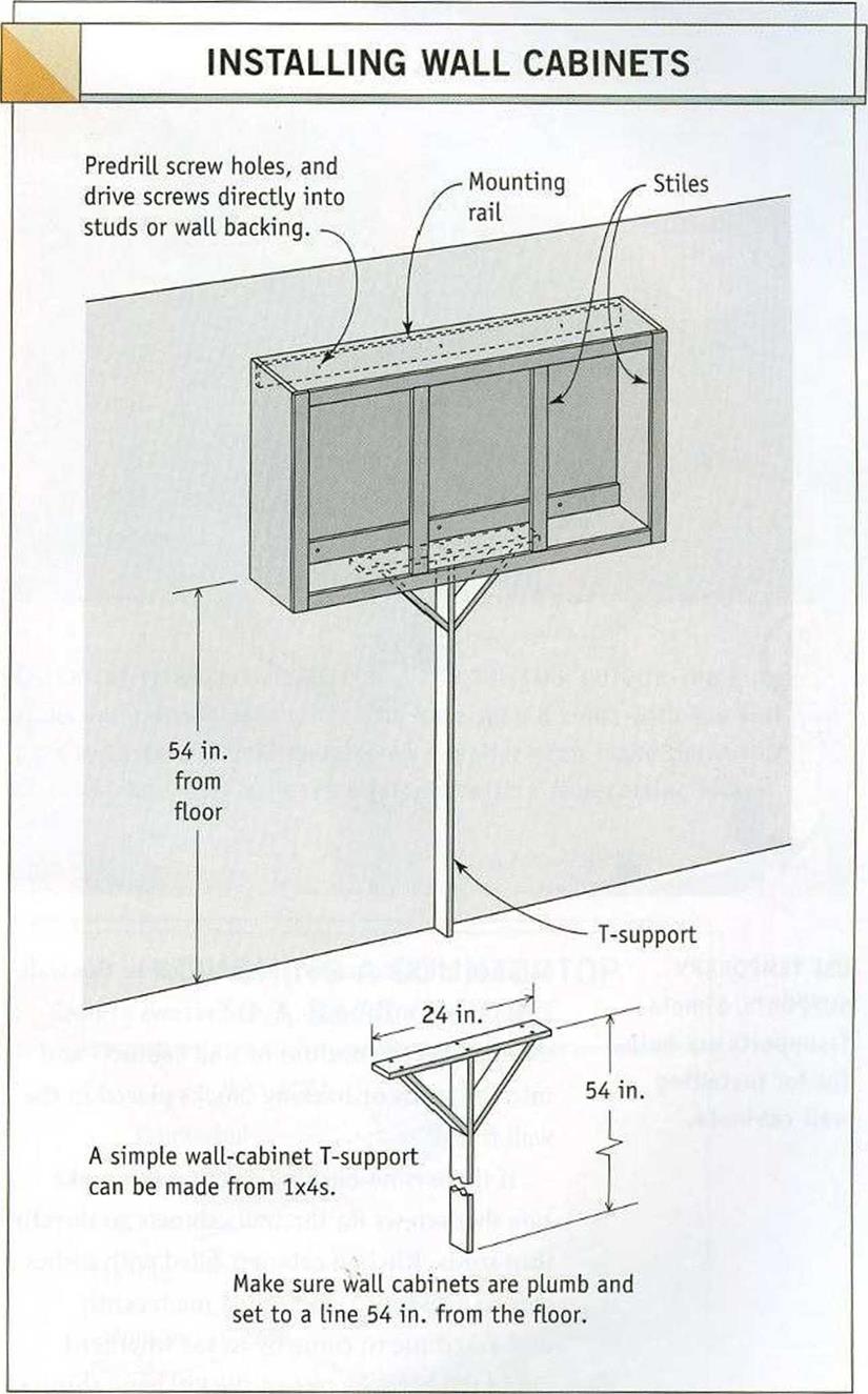
Wall cabinets are usually installed with their bottom edges 54 in. from the floor, or 18 in. above a countertop (see the illustration above). Mark a level line for the wall cabi­

nets with a soft pencil, so that it can be erased or easily covered with paint. If there is a kitchen soffit (discussed in chapter 5), make sure the cabinets are secured to the walls, with their tops fitting snugly against the soffit.

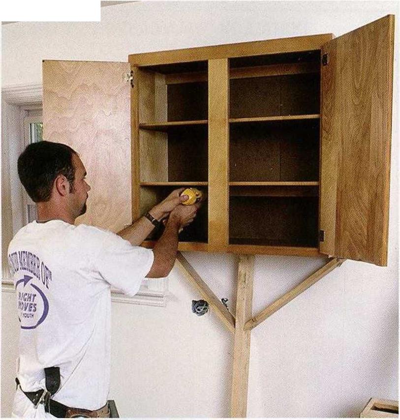
Before hanging wall cabinets, remove the doors and shelves to make the cabinets lighter. Just as with base cabinets, start in a corner and install every unit level and plumb. Use a T-support or something similar to hold a

Install the base cabinets in kitchens and baths

Install the base cabinets in kitchens and bathsПодпись: USE TEMPORARY cabinet in place until it is attached to the wall SUPPORTS. Simple (see the photo above). Drive screws at both T-supports are help- the t0p anc| the bottom of wall cabinets and ful for installing into the studs or backing blocks placed in the wall cabinets. n r wall frame. If there is no backing in the walls, make sure that screws for the wall cabinets go directly into studs. Kitchen cabinets filled with dishes can be heavy. A friend called me recently and asked me to come by to see whether I could tell her why one of the kitchen cabinets in her new house was sagging. It turns out the installer missed the studs when screwing the cabinet to the wall. To make sure that doesn’t happen, find the location of studs, then transfer those locations to the inside of each cabinet. An electronic stud finder will locate studs quickly and accurately. But if you don’t have one, there are other methods you can use. Look on the floor for keel marks that were used to locate the studs before drywall installation. Electrical-outlet boxes are nailed into

studs. Tap gently on the wall and listen for a duller sound when you tap over a stud. Or drive nails behind the cabinet to locate a stud. When one stud is found, other studs should be 16 in. or 24 in. from it. Once the studs are found, mark their locations inside the cabinets on the mounting rail. Predrill screw holes in the cabinet mounting rail, set the cabinet in place, and drive a screw into each stud. If the screw misses the stud, check again for its loca­tion until you get it right. And feel free to use a few extra screws in wall cabinets. Just make sure they go into studs.

Machinery: hydraulic mills and wheels, lifting machines and norias Lifting machines

Water lifting machines respond to a very basic need of civilization – that of raising water from a river, canal, or cistern for its distribution to agricultural or urban uses. The Near East had used the shaduf (Figure 2.4), a balance-beam device, for a very long time – but this device was not used in China. We have seen that more sophisticated devices appeared in Egypt during the period of Alexandria (the end of the 3rd century BC), then in the Roman Empire. Examples include the Ctesibios pump (Figure 5.5), the Archimedes screw (Figure 5.3) and the muscle-powered lifting machine (Figure 6.20).

The first written evidence of lifting machines in China is found in a treatise of Wang Ching during the latter Han period (80 AD). We cited this treatise earlier in summariz­ing the innovations of the Han period, and here is a specific extract:

“In the streets of the city of Loyang there was no water. It was therefore pulled up from the

River Lo by water-men. If it streamed forth quickly (from the cisterns) day and night, that was 82

their doing”.

Another text from 189 AD is more explicit, again concerning the question of water supply in the capital Luoyang:

“He (the minister Chang Jang) further asked Pi Lan to cast bronze statues… and bronze bells… and also to make (to cast) “Heavenly Pay-off” and “Spread-eagled Toad” (machines) (which would) spout forth water. These were set up to the east of the bridge outside the Phing Men (Peace Gate) where they revolved (continually, sending) water up to the palaces. He also (asked him to) construct square-pallet chain-pumps and “siphons”, which were set up to the west of the bridge (outside the same gate) to spray water along the north-south roads of the

city, thus saving the expense incurred by the common people (in sprinkling water on these

83

roads, or carrying water to the people living along them).”

This text refers to the simultaneous use of several different machines. According to Joseph Needham and his collaborators, the siphons mentioned here are probably simple piston pumps, like those used in China to pump brine from the salt mines. Perhaps other machines in use were manual lifting wheels.

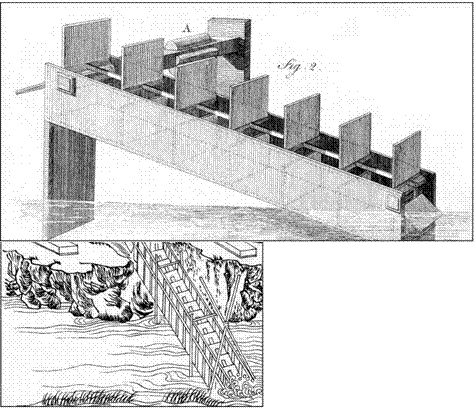
The pump with chain and square paddles (rectangular, in fact), also called the drag­on backbone machine, is explicitly mentioned in the text. It is typical of Chinese inven­tions, and Figure 8.18 gives an idea of its workings. It is a wooden chain fitted with rec­tangular paddles, circulating in a long wooden flume that is open at each end, inclined at 25° or less from the horizontal. Water is lifted by the upwards movement of the pad­dles inside the flume. The chain to which the paddles are fixed was originally powered by men (or young girls) on a pedalboard. But from the 12th century one encounters descriptions of these machines as powered by animals, and even by hydraulic wheels. The lifting height can be of the order of 5 meters.

Rice cultivation developed rapidly under the Tang and the Song, and this agriculture requires intensive irrigation. The authorities favored the dragon backbone machine to lift water into the rice fields. In 828 they even standardized the specifications for this pump, whose great success can be attributed to its ergonomics. In the 12th century its use in Turkestan is noted on the occasion of a voyage of a Taoist wise man, then it appears in Korea in the 15th century. Between the 17th and 19th centuries it is used to various extents throughout the world.[446] [447]

A parallel technology to the dragon backbone machine is the noria. This hydraulic – powered lifting machine is already well known to us – in Chapter 6 we cited the descrip­tion given by the Roman Vitruvius in about 25 BC, and we have seen its very broad use in Syria and in the Arab world. But the history of its introduction in China is an enig­ma. There is clear evidence of the use of hydraulic energy in China ever since the begin­ning of the Christian era, but the Chinese hydraulic wheels appear to be mostly horizon­tal, with vertical axes. The noria appears in Japan about 800, but one cannot find seri­ous evidence of its use in China before the 10th century, and indeed there is no indis­putable evidence prior to 1130. When one encounters the noria in Korea in the 15th cen­tury, it appears as an alternative lifting technology to the square-pallet chain pump, and it comes from Japan, not China.[448] These observations suggest that there may have been

Machinery: hydraulic mills and wheels, lifting machines and norias Lifting machines

two pathways for the introduction of the noria in Asia: by land in the region of the upper course of the Yellow River in China on the Silk Road around the 10th century; and in Japan by sea from India two centuries earlier.

In his account of his Voyage in China (1345), Ibn BattUta describes wheels on the Yellow River that appear to be norias:

“(The Yellow River) is lined with villages, cultivated fields, orchards, markets, in the manner of the river Nile in Egypt; but here the land is more flourishing, and on the river there are a large number of hydraulic wheels.”[449]

The Chinese noria is very light, made of wood and bamboo, and therefore it can be turned by a weak current. The most famous of these wheels are those in the region of Lanzhou on the upper course of the Yellow River. Some fifteen meters tall, they are arranged in batteries or sets of up to ten per row.[450]

Machinery: hydraulic mills and wheels, lifting machines and norias Lifting machines

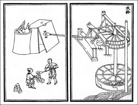
Figure 8.19 Forge bellows powered by hydraulic force; illustration of 1313 (from Needham and Ling, 1965).

We have seen that the bucket chain or saqqya was widely used in the Arab world. But it was used only marginally in China, and then probably only in the salt mines of Sechouan at a relatively late date.[451]

Wall Sheathing After Walls are Standing

1. Make sure the first piece goes up plumb. If you are installing more than three pieces in a row, use a level to set the first piece plumb.

2. It is easier to install the plywood if you are able to fit a 16d nail between the concrete foundation and the mudsill.

a. Place two nails under each piece near each end.

b. Remove the nails when you are finished.

3. The easiest and fastest way to handle an opening in the wall is to just sheath over it, then come back and use a panel pilot router bit to cut out the sheathing.

Roof Sheathing

1. Make sure the first piece goes on square.

2. Chalk a line from one end of the roof to the other.

• When measuring for the chalk line, make sure you consider how the plywood intersects with the fascia. The plywood may cover the fascia, or the fascia may hide it.

3. If the sheathing overhang is exposed, the sheathing could take a special finish.

• If the exposed sheathing is more expensive than the unexposed sheathing, then often the exposed sheathing is cut to fit only the exposed area. In this situation, cut the sheathing so that it breaks in the middle of the truss or rafter blocking.

4. 24" is the minimum width of any row of sheathing. Check before you get to the last row in case you need to cut a row so the last row will be at least 24".

Nailing Sheathing

1. Read the information on the stamp on each piece of plywood. Make sure you are using the right grade. Sometimes the stamp will tell which side should be up.

2. There should be at least a 1/8" gap between sheets for expansion.

3. The heads of the nails must be at least 3/8" from the edge of the sheathing.

4. Make sure that the nail head does not go so deep that it breaks the top veneer of the sheathing. Control nail gun pressure with a pressure gage or depth gage.

5. Angle the nail slightly so that it won’t miss the joist, stud, or rafter.

6. Use the building code pattern for walls, floors, and roofs. Always check the plans for special nailing patterns. (Most shear walls have special patterns.)

Installing Hold-Downs (while walls are being built)

1. Locate wall hold-downs on plans and check details.

2. Locate holes to be drilled for hold-downs, anchor bolts, and through-bolts.

• Measure location for through-bolts.

• Center hold-downs on plates.

• Center hold-downs in post or align with anchor bolts.

3. Drill holes.

4. Nail post into wall.

5. Nail sheathing to wall.

6. After wall is standing, install hold-downs, bolts, washers, nuts, and through-bolts.

7. Tighten all bolts and nuts.


Installing Hold-Downs (after walls are built)

1. Select a work area (large, close to material).

2. Check the plans for the location, quantity, and other details of hold-downs.

3. Collect all material and tools needed.

4. Spread hold-down posts for common drilling (Cut if necessary.)

5. Mark hold-down posts for drilling.

6. Drill for posts with holes 1/16" larger than the bolts.

7. Loosely attach hold-downs, bolts, washers, and nuts to posts.

8. Spread hold-downs to installation location.

9. Drill holes for through-bolts if necessary.

10. Place hold-down in wall.

11. Place through-bolts into hold-downs where required.

12. Tighten all nuts.

13. Nail posts to plates.

14. Nail sheathing to posts.

Teaching installing hold-downs after walls are built

oivd^e

Teaching installing hold-downs while walls are being built

Removing Temporary Braces

1. Remove temporary braces only after the walls have been secured so that they will not move.

2. A sledgehammer provides a fast and easy way to remove the braces.

3. Knock a number of the braces off at one time. Be careful that no one steps on the nails before you remove them.

4. Put the removed braces together.

5. Hit the point end of the nail to expose the nail head.

6. Use a crowbar to remove the nails.

7. If you do not have many braces, a hammer is an easy way to remove them.

Forced-Air Heating

Throughout most of the country, forced air is the most common form of heating and cool­ing in new construction. Besides quick re­sponse time, the main advantage of forced – air heating lies in the opportunity it gives the homeowner to commission modifications and additions to standard equipment to cre­ate a healthy air-distribution system. A modi­fied system can control humidity, filter air, and introduce fresh, conditioned air from the out­side. Disadvantages of a forced-air system may include greater operating costs, noisy opera­tion, larger space requirements for equipment installation and ductwork housing, deple­tion of negative ions, and the need for regular maintenance and cleaning of ductwork to pre­vent mold and dirt buildup.

Disadvantages of a standard forced-air system can also include distribution of odors and particulate matter, and unwanted dehu­midification. Forced-air heating, which heats air, is considered to be far less comfortable than radiant heating, which heats objects. A forced-air system must be properly designed for appropriate balancing and distribution. Poor indoor air quality, energy inefficiency, and discomfort can result when system design is inadequate.

If forced air is your choice for heating and cooling (in much of the country this may be the only cost-effective choice), you can take advantage of the whole-house air distribution ducting that will already be in place to improve air quality by implementing the steps below:

• Use a fresh-air intake vent from the outside to the furnace to introduce and distrib­ute fresh, tempered ventilation into your home. Locate the vent so that it receives “fresh” air; do not place the vent near trash storage areas or where auto exhaust and other pollutants could be brought inside the house.

• Install enhanced filtration in your forced – air stream. (See the Air Filtration section below.)

• Choose a furnace with sealed combustion to avoid the entry of combustion byprod­ucts into the airstream.

Design of Healthier Forced-Air Ductwork

Care must be taken during the design, instal­lation, and maintenance of forced-air duct­work because the means of air distribution is often the source of allergies and other health problems associated with forced-air heating and cooling.

Ductless air plenums are a common source of air contamination associated with HVAC systems. Joisted floors, and wall cavi­ties without ductwork, act as pathways for contaminated attic or crawl space air to en­ter the building if air is forced through them. Fibers from wall and ceiling insulation are frequently sucked into the return side of the heating system and circulated throughout the building envelope. Furthermore, the plenums are inaccessible for cleaning and impossible to seal.

Floor registers should be avoided because debris will inevitably accumulate in them, not only during construction but also in the course of occupancy. For this reason, supply and return registers should ideally be located on walls or ceilings. Below-slab ductwork should be avoided because it can collect mois­ture and dirt, providing a breeding ground for microbes. Also avoid running ductwork through uninsulated spaces if at all possible. If this is unavoidable, the ductwork should be well insulated on its exterior.

Ductwork should be easily accessible for future inspection and maintenance. A good design should specify cleaning portals that will give access to all ductwork, especially points of probable condensation. Sheet metal is preferable to plastic flex ducts because the flex ducts are difficult to keep clean and are easily damaged. Ductwork may be coated with undesirable oils from the manufacturing process and should be cleaned of all oil prior to installation.

Installation of Forced-Air Ductwork Quality control during the installation of a well-designed ductwork system will help en­sure optimum efficiency and health. Ductwork should be well sealed with a nontoxic sealer. Ideally, an air distribution system should have a neutral effect on building pressurization.

A large amount of dust and debris is gen­erated during the construction process, and it frequently finds its way into the ductwork, becoming a source of air contamination once the system is in operation unless measures are

Forced-Air Heating

The Problem: Home investigation revealed that ductwork had not been sealed on the return side of this system causing contaminated air to be sucked in to the system and blown throughout the home. Recommendation: All ductwork should be thror – oughly sealed and tested for air leakage.

Photo: Restoration Consultants.

taken during construction to keep the duct­work clean.

In order to achieve an optimal ductwork system installation, we suggest the following specifications:

• Metal ductwork shall be free of all oil resi­dues prior to installation.

• Ductwork shall be well sealed with non­toxic compounds such as AFM Safecoat DynoFlex, RCD6, Uni-Flex Duct Sealer, Uni-Mastic 181 Duct Sealer, United Duct Sealer (Water Based), or approved equal. Mastics shall be water resistant and water-based, with a flame spread rating no higher than 25 and a maximum smoke developed rating of 50.

• During construction, the ends of any par­tially installed ductwork shall be sealed with plastic and duct tape to avoid the

introduction of dust and debris from con­struction.

• All forced air must be ducted. The use of unducted plenum space for the transport of supply or conditioned air is prohibited.

• Cloth duct tape shall not be used. (It has a high failure rate that can result in unde­tected leakage.)

• All joints, including premanufactured joints and longitudinal seams, shall be sealed.

• Gaps greater than Vs inch shall be rein­forced with fiber mesh.

• All ductwork running through uninsu­lated spaces shall be insulated to a mini­mum of R-io to prevent condensation problems and to save energy.

• Any ductwork requiring insulation shall have the insulation located on the outside of the ducts.

• Ductwork must be professionally cleaned prior to occupancy. The duct-cleaning

A Constant Supply of Warm Dust

A retired couple contacted John Banta because they were experiencing eye irritation and diffi­culty breathing caused by dust in their home. In spite of frequent vacuuming and dusting, an un­usually heavy deposit of dust was noted on the furnishings during the house inspection. John suspected that the furnace system was the source of contamination because the heat registers in the home were lined with a fine dust and the clients’ symptoms worsened when the furnace was on.

John was puzzled, though, by the lack of dirt on the cold air return filter and the absence of air movement. He opened the cold air return and ex­amined the inside wall to see if there were any vis­ible obstructions. To his surprise, he found no duct at all. The cold air return was a dummy and went nowhere.

Further investigation revealed that the fur­nace and duct system were located in the crawl space under the home. John inspected the crawl space, where he discovered that there was no con­nection between the cold air return port on the furnace and the rest of the house. In fact, the fur­nace was taking cold air from the crawl space and blowing the unfiltered, contaminated air directly

can influence the ultimate outcome. For this reason we have provided specifications for the contractor where relevant. Finally, a regular cleaning and maintenance program is essen­tial for optimal efficiency. This task will ulti­mately fall to the owner and may influence your choice of HVAC system.

Choice of Fuel Source

Gas and other sources of combustion fuels can pollute the airstream if you do not plan care – into the house. Consultation with a heating and air conditioning company was recommended to cor­rect this construction defect.

Discussion

HVAC duct systems should always be leak-tested to ensure that they meet specified standards. The stated industry standard for a sealed duct sys­tem is less than 3 percent leakage, which is rarely achieved. The furnace itself will account for much of the leakage since it is difficult to seal. The fur­nace should be mounted in a clean, easily acces­sible area such as a mechanical room and not in an attic or crawl space.

Leakage also occurs at unsealed joints where the metal ducts fit together. Since the return side of the furnace is sucking air back into the furnace, it will suck contaminants through leaks in the duct­work. If the unsealed ducts pass through walls or attics containing fiberglass, fiberglass particles are sucked into the ducts and blown into the house. If the unsealed ducts are in a crawl space under the home, then moldy, pesticide-laden or dusty air can be sucked into the furnace system and blown into the house.

fully. Electric heat is often considered “cleaner” heat because combustion does not occur in the home. However, environmental pollution from electricity generation plants must be ac­knowledged. Moreover, electric heating ap­pliances generate electromagnetic fields, an invisible and often overlooked source of pol­lution. Whatever your choice of fuel source, there are several strategies that can be em­ployed in the mechanical room that will make heating healthier.

Mechanical Room Design

• The mechanical room should be a dedi­cated room, insulated and isolated from the living space either in a separate build­ing or in a well-sealed room that ventilates to the outside. It should be easily accessible for regular routine maintenance.

• The equipment in the mechanical room may produce elevated levels of electro­magnetic fields and should not be located adjacent to heavily occupied living spaces.

• Ensure the supply of adequate combustion air to the mechanical room.

• We recommend that you locate a fire alarm in the mechanical room.

• If there is a water source in the mechanical room, there should also be a floor drain.

Heating and Cooling Appliances

We recommend the following guidelines for choosing, locating, and maintaining heating equipment:

• Purchase equipment designed for back – draft prevention.

• Use sealed combustion units to prevent transfer of combustion byproducts into the airstream. This is especially important where the mechanical room must be ac­cessed directly from the living space.

• If you are using a forced-air system, we strongly recommend adding a good com­bination filtration system that will filter out both particulate matter and gas.

• If possible, choose a heating system that does not run hot enough to fry dust. Hy – dronic systems and heat pumps meet this requirement.

• Institute a regular maintenance program to clean components, change filters, and purge mold or mildew growth.

Hydronic Heating

Hydronic heating, delivered through hot wa­ter, is usually a wall-mounted baseboard or radiant floor system. Baseboard systems are usually made of copper tubes and aluminum radiating fins with painted steel covers. Base­board radiators can be noisy if not maintained, and they can become traps for dust and dirt. Some baseboard units are subject to outgas – sing at first, when the factory-applied paint on them gets hot. Verify with the manufacturer if this will be a problem with the model you are considering.

Hydronic radiant floor systems are usu­ally made of plastic, rubber, or copper tubing installed within or under the floor. Hot water circulating through the tubing heats the floor mass and the heat then rises through gentle convection. Radiant systems are silent and clean. Because this form of heating heats feet, occupants are comfortable at lower operat­ing temperatures. The water running through the piping is not hot enough to fry dust. Note that hydronic radiant floor heating should not be confused with radiant electric heating, in which the heat source is heated electrical wir­ing. We do not recommend this type of heat­ing because it will distribute a magnetic field throughout the home when in operation.

At one time, radiant floor heating used copper tubing almost exclusively but the ris­ing price of copper, combined with the intro­duction of plastic and rubber tubing, made this a less common option. Metal tubing, such as copper, can conduct electromagnetic fields through the structure if it becomes charged at any point along its route and for this reason we do not recommend it. Some in-floor systems use very odorous rubber products. While this is not a problem where they are embedded in concrete, it can be a source of indoor pollution where the tubing is exposed at access points. Wirsbo Hepex, a crosslinked polyethylene tubing, or Kitec, a crosslinked polyethylene tubing with an aluminum core, are odorless products for radiant floor heating.

The advantages of a hydronic system in­clude slightly lower operating costs, even heating, quieter operation, ease of zoning, and independent room-temperature control. Disadvantages of the hydronic system include slow response time and higher installation costs compared to forced air because of the number of mechanical components.

Installing the Five-by-Ten Rafters

As with the four-by-eight floor joists, we used two different methods of extending the five-by-ten radial roof rafters. The existing rafters, protected by a good overhang, were in excellent condition and extended between 18 and 23 inches (43.7 and 58.4 centimeters) from the cordwood walls. On the east and west rafters (which eventually would have supporting cordwood walls below them), we left the original overhanging rafters as they were, but cut a 2-by-io by 22-inch (5.1-by-

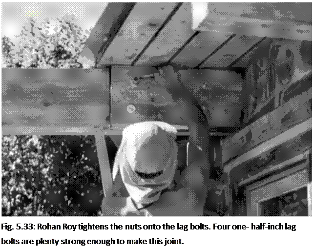
25.4 by 55.9-centimeter) piece out of the new rafters so that they could fit up to the side of the overhanging rafters, as seen in Fig. 5.33. Then we used four one-half – by eight-inch lag bolts to hang the new rafter onto the old. The hex-heads and washers show on the outside. Carriage bolts are an option here.

Подпись: Fig. 5.33: Rohan Roy tightens the nuts onto the lag bolts. Four one- half-inch lag bolts are plenty strong enough to make this joint. Notice, in Fig. 5.33, that the original red pine rafter twisted slightly after construction, as red pine is inclined to do. I was able to straighten the rafter extension by making a biased cut out of the new rafter. This made for a tricky chainsaw cut. The key to success in this sort of thing is to mark the angle correctly on the piece to be cut. And the key to marking it correctly is to double – and triple­check your angles and measurements. As I tend towards a slight dyslexia on this sort of thing, I would explain what I was doing to willing ears such as Rohan’s. He picks up quickly on wooly-minded thinking.

After the framing was completed, and the roof installed, we covered this rather unattractive join with cordwood masonry. The outside looks great, as if it’s a single rafter originating from the center of the house. On the inside, no rafter is in evidence, as it is hidden behind short log-ends.

The other three rafter extensions would be exposed in the room, so appearance was important. I designed a rafter plate which could be made from standard one-quarter – by 8-inch (.63- by 20.3-centimeter) steel stock. A twelve – foot section of this material was cut at the local Steel Service Center into six 24- inch (61 centimeter) pieces. I made a hole-drilling pattern out of a piece of plywood, and my friend Bruce Kilgore kindly drilled all the one-half-inch holes for me with his drill press. Before installation, Anna Milburn-Lauer painted all six pieces with two coats of spray-on flat black enamel.

As already stated, truss plates must be used on both sides of the joint for strength. Now, you may be tempted to try to fasten both plates to the rafter by the use of six-inch lag bolts, but leave that temptation behind. The chances of the holes of both plates lining up with holes drilled through the rafter are slim to nil. I saw

an architect-designed detail like this on a job once, where eight-by-eight posts were supposed to be installed into pre­drilled heavy metal U-shaped post holders, already fastened to the foundation. The architect wanted bolts all the way through, but the contractors couldn’t hit the hole in the plate on the other side, even with their long bits. Lag screws from each side, however, are plenty strong, and that’s what we chose.

Подпись: • 4Подпись: *Подпись: Fig. 5.34: Anno tightens log screws up ogoinst the metol plote, which acts as its own washer. Rohan drills three-eights-inch holes for the plate on the other side, appropriate for one-half-inch lag screws. He hangs the plate in position on two small screws, which hold it in place while he drills his holes.image141Each plate would require eight half-inch by з^-іпсії (1.2- by 9.0- centimeter) hex-headed lag screws. Six times eight is 48. It was quite a bit cheaper to buy two boxes with 25 screws per box than to buy 48 pieces out of the bin. So I have two left over.

The new rafter was butted up to the old rafter, with its south end supported by the new girder system, just installed. We jammed a two-by-four under the north end of the new rafter to hold it firmly against the end of the overhanging old rafter. Rohan and Anna installed the plates, as seen in Fig. 5.34.

DEFINITIONS

Stone mastic asphalt is defined as a gap-graded asphalt mixture that has bitumen as a binder, and is composed of a coarse crushed aggregate skeleton bound with a mastic mortar.

The standard defines two types of recipes (job mix formulae [JMF]):

• Input target composition—this is the determined composition of the mix­ture given through listing its constituent materials, the gradation curve, and the percentage content of binder added to the mixture; this formula is the result of laboratory validation of the mixture.

• Output target composition—this is the determined composition of the mixture given through listing its constituent materials, the midpoint grada­tion, and the percentage of soluble binder content in the mixture, which are obtained as results of the composition analysis (extraction) of a produced mixture; usually this formula is the result of production validation of the mixture.

An additive is defined as a constituent material supplemented to the mixture in small amounts, (e. g., organic or nonorganic fibers and polymers added to enhance mechan­ical properties, workability, or the color of the mixture).

A wall against the sea – the tidal bore of Hangzhou

The major city of Hangzhou, prominent in the account of Marco Polo as we have seen, is located at the head of an estuary that is nearly 100 km long. The land there is quite flat and thus exposed to the tidal surge and waves associated with strong storms. Moreover in this particular estuary there is an additional extraordinary phenomenon: one of the largest tidal bores in the world.

The tidal bore is a wavelike disturbance, or a series of disturbances, resulting from the progressive steepening of the tidal wave as it propagates into a sufficiently long and shallow estuary. At Hangzhou in the Chien-Thang estuary the mean height of the bore is the order of two meters. But during equinox tides, it can reach 7 or 8 meters. It is very special to be able to come to see this bore during extreme tides, a truly festive occa­sion. Here is a poetic description dating from the 13th century that gives some idea of the power of this phenomenon:

“The tidal bore on the Che River is one of the great sights of the world. It reaches its full force from the sixteenth to the eighteenth of the month. When it begins to arise far away at Ocean Gate, it appears but a silver-thread; but as it gradually approaches, it becomes a wall of jade, a snow-laden ridge, bordering the sky on its way. Its gigantic roar is like thunder as it con­vulses, shakes, dashes, and shoots forth, swallowing up the sky and inundating the sun, for its force is supremely vigorous. “[441]

Подпись: Figure 8.17 Detail of a sketch from 1610, Observation of the tidal bore (Deutsche Staatsbibliothek, Berlin).A wall against the sea - the tidal bore of HangzhouFigure 8.16 The city of Huzhou, near the south bank of Taihu lake. This city is linked to Hangzhou and to the Grand Canal by a network of canals. “It is one of the largest and most considerable cities of China, due to its richness, its commerce, the fertility of its land, and by the beauty of its waters and mountains.” (du Halde, 1735 – ancient archives ENPC).

The earliest land protection works along this estuary date from the time of the latter Han, around 85 AD. The name of the estuary, the estuary of the dike of coins, also dates from this period. The first builder of the dike was the governor of the region called Hua Hsin. He had called upon the people of the region to bring earth and stones for the proj­ect, for which they were paid in coins. The dike is exposed to the force of the waves, and the sea apparently destroyed the first few attempted structures. There ensued debates on the mode of construction that should be adopted. Should the dike be built of earth with a rock armor layer, a costly solution? Or should it be built more simply of earth mixed with straw and brush, as were many other dikes and dams? One can also imagine a structure based on rocks contained in bamboo cages, anchored with stakes and stabilized with iron chains, an assembly commonly used to repair fluvial dike breaches. Work was conducted in 910, in 1014, again in 1035, then again in 1169…. Gates were put in place to let the water flow seaward at low tide.

A continuous rock dike supported by an earth fill is eventually achieved in 1368. In the Ming Dynasty, in 1448, a solution is finally found that has remained satisfactory up to the present time. This consists of constructing a wall of cut stone interconnected with steel pins and with a stairstep profile facing the waves, better to break their force. Its foundation is made of wood piles, and the wall leans against old rock outcrops as well as against an earth fill.[442] [443] This type of construction is similar to that used for the large dike of Hongze lake described earlier.

80

Initially this maritime dike was probably about 80 km long. Today, it is more than

350 km long, and its crest rises more than eight meters above sea level.[444] [445]

Residential Heating and Cooling

Methods of heating, cooling, and ventilating homes have many important health ramifi­cations that will affect us long after the initial building materials have outgassed and reached a neutral state. If we lived in a pristine natu­ral environment with low humidity and mild temperatures, we would be able to condition our homes without mechanical assistance by means of solar gain, shading, and cross­ventilation. Residents throughout most of North America do not have this luxury. Cold and cloudy winters, hot and humid summers, and polluted or pollen-filled air are realities from which homes must shelter occupants.

We have come to expect a level of comfort and temperature control in our homes un­dreamed of by our not-too-distant ancestors. Along with the increased comfort level, we have unwittingly come to accept many health problems associated with heating and cooling

Подпись: The Problem: Crawl space air was being drawn in to this home through plumbing penetrations before they were sealed Recommendation: Plumbing and other penetrations should be sealed to prevent infiltration. Photo: Restoration Consultants.

systems. In fact, more than any other build­ing system or component, heating and cooling methods can be a major cause of sick building syndrome. Some of the problems include:

• toxic fumes from gas, oil, or propane fuels that work their way into the building enve­lope through leaky supply lines, from in­sufficiently ventilated or improperly sealed mechanical rooms, and from open com­bustion appliances

• backdrafting of hazardous and sometimes deadly gases into the living space from flues

• infiltration of pollutants from outside the building envelope resulting from depres­surization

• fried dust resulting from hot surface tem­peratures on heating appliances

• circulation of dust through an unfiltered forced-air heating system

• contamination from mold growing in the ductwork and air conditioning equipment

• fiberglass fibers from ductwork insulation that circulate in the living space

In the following section we focus on ways of reducing the need for mechanical heating and cooling. Later in this chapter we present guidelines for healthier heating and cooling installations, language for specifications, and maintenance suggestions that will help elimi­nate some of the problems mentioned above.

Reducing Heating and Cooling Loads Through Design Strategies

The application of a few simple design and planning principles can greatly reduce the amount of mechanical heating and cooling required to live comfortably, thereby improv­ing health and lowering energy consumption. In designing your home for energy efficiency, consider the following suggestions.

Create an Energy-Efficient Building Envelope

• Choose an exterior wall system with a high insulation value.

• Choose interior wall and floor systems with high levels of thermal mass to assist in

Подпись: This winter garden located in New Mexico provides a large portion of the home's heat in the winter. A small overhang prevents excessive solar gain from the high summer sun. Architect: Paula Baker-Laporte; Builder: Econest Building Co. Photo: Lisl Dennis.

keeping things cool in summer and retain­ing heat in winter.

• Seal cracks and joints to prevent unwanted infiltration and exfiltration.

• Choose a high insulation value for the ceil­ing. This measure will be especially cost ef­fective because most heat escapes through the roof.

Consider the Surrounding Site as an Extension of Your Climate-Control Design

• Make use of deciduous trees to shade in summer and allow solar gain in winter.

• Observe prevailing wind patterns when planning for natural ventilation.

• Consider using trees as windbreaks to lower the heating load created by cold win­ter winds.

• Situate your home as far away from pollu­tion sources as possible so that the site can provide a quality air supply for home ven­tilation.

Take Advantage of Solar Heat

• Orient the home to take advantage of solar gain.

• Plan fenestration (arrangement of doors and windows) for the desired amount of heat gain.

• Make use of overhangs and sun angle in­formation to prevent overheating in sum­mer.

• Use light colors to reflect heat and dark colors to absorb and store heat.

• Provide thermal mass for heat storage.

• Provide cross-ventilation to facilitate nat-

Подпись: This "Tulikivi" brand masonry oven works on the principal of contra-flow design and mass storage capacity providing comfortable and energy efficient heat. Architect: Paula Baker- Laporte; Builder: Econest Building Co. Photo: Lisl Dennis.

ural air exchange and to provide cooling in summer.

• Use thermal window-shading devices to control heat loss.

• Use specialized window coatings to en­hance solar gain where desired and block unwanted heat gain.

Become a More Active Participant in Temperature Control

• Open and close windows to provide fresh air and control temperature.

• Open and close thermal shading devices to control heat gain and loss.

• Utilize automated thermostat controls to economize on heating and cooling when you are absent or asleep.

• Be willing to add and subtract layers of
clothing to allow for a greater range of ac­ceptable temperatures.

• Consciously acclimatize your body to a broader comfort range.

Healthier Heating and Cooling

Each heating and cooling system has advan­tages and disadvantages that you must weigh carefully when choosing a system that best fits your needs and budget. Once you have made a choice, there are several design, construction, and maintenance considerations that will op­timize performance and minimize the health risks of the system. In the preliminary design phase, you and your architect must consider factors such as the location of the mechani­cal room. During the construction phase, the choice of materials and installation procedures

CASE STUDY 15.1