Tangible costs in risk-based design

Design of a hydrosystem infrastructure, by nature, is an optimization prob­lem consisting of an analysis of the hydraulic performance of the structure to convey flow across or through the structure and a determination of the most economical design alternative. The objective function is to minimize the sum of capital investment cost, the expected flood damage costs, and operation and maintenance costs. The relevant variables and parameters associated with the investment cost and the expected damage costs of a hydraulic structure, i. e., a highway drainage structure, are listed in Tables 8.1 and 8.2, respectively. The maintenance costs over the service life of the structure generally are treated as a yearly constants. Based on Tables 8.1 and 8.2, the information needed for the risk-based design of hydraulic structures can be categorized into four types:

1. Hydrologic/physiographic data include flood and precipitation data, drainage area, channel bottom slope, and drainage basin slope. These are needed to predict the magnitude of hydrologic events such as streamflow and rainfall by frequency analysis and/or regional analysis.

Pipe culverts

Box culverts

Bridges

Parameters

Unit cost of culvert

Unit cost of concrete Unit cost of steel

Unit cost of bridge

Variables

Number of pipes Pipe size Pipe length Pipe material

Number of barrels Length of barrel Width of barrel Quantity of concrete Quantity of steel

Bridge length Bridge width

SOURCE: After Tung et al. (1993).

TABLE 8.1 Variables and Parameters Relevant in Evaluating Capital Investment Cost of Highway Drainage Structures

2. Hydraulic data include flood-plain slopes, geometry of the channel cross sec­tion, roughness coefficients, size of the structural opening, and height of the embankment. These are needed to determine the flow-carrying capacities of hydraulic structures and to perform hydraulic analysis.

TABLE 8.2 Damage Categories with Related Economic Variables and Site Characteristics in Risk-Based Design of Highway Drainage Structures

Подпись: Floodplain property damage: Losses to crops Losses to buildingsПодпись: Damage to pavement and embankment: Pavement damage Embankment damage Подпись: Traffic-related losses: Increased travel cost due to detour Lost time of vehicle occupants Increased risk of accidents on a flooded highway

Подпись: Location of crop fields Location of buildings Physical layout of drainage structures Roadway geometry Flood characteristics Stream valley cross-section Slope of channel profile Channel and floodplain roughness Flood magnitude Flood hydrograph Overtopping duration Depth of overtopping Total area of pavement Total volume of embankment Types of drainage structure and layout Roadway geometry Average daily traffic volume Composition of vehicle types Length of normal detour paths Flood hydrograph Duration and depth of overtopping Подпись: Types of crops Economic value of crops Types of buildings Economic values of buildings and contents
Подпись: Material cost of pavement Material cost of embankment Equipment costs Labor costs Repair rate for pavement and embankment
Подпись: Rate of repair Operational cost of vehicle Distribution of income for vehicle occupants Cost of vehicle accident Rate of accident Duration of repair

Damage category Economic variables Site characteristics

SOURCE: After Tung and Bao (1990).

3. Structural data include material of substructures and layout of structure.

4. Economic data include (a) type, location, distribution, and economic value of upstream properties such as crops and buildings, (b) unit costs of structural materials, equipment, operation of vehicles, accidents, occupancy, and labor fee, (c) depth and duration ofovertopping, rate ofrepair, and rate ofaccidents, and (d) time of repair, and length of detour.

In the design of hydrosystem infrastructures, the installation cost often de­pends on environmental conditions, such as the location of the structure, ge – omorphic and geologic conditions, the soil type at the structure site, type and price of construction material, hydraulic conditions, flow conditions, recovery factor of the capital investment, and labor and transportation costs. In reality, these cost-affecting factors would result in uncertainties in the cost functions used in the analysis. However, a practical way to incorporate economic uncer­tainties in the risk-based design of hydrosystem infrastructures remains to be developed.

NOISE BARRIERS

James J. Hill, P. E.

Structural Engineer
Consultant
Anoka, Minnesota

Roger L. Brockenbrough, P. E.

President

R. L. Brockenbrough & Associates, Inc.
Pittsburgh, Pennsylvania

During recent years, there has been increasing concern over noise generated by highway traffic in urban areas. Noise abatement programs have been implemented by many agencies. Source control methods have included the development of quieter pave­ments, quieter tire tread patterns, and speed restrictions. In some regions, noise levels have been reduced by depressing roadways or building tunnels, or by special designs of adjacent buildings. In many cases, however, noise reduction has been achieved through controlling the noise path by the design and construction of noise barriers. Sometimes referred to as sound barriers or noise walls, these longitudinal walls are built specifically to reduce traffic noise. In addition to their primary purpose, noise barriers are sometimes adopted to shield unsightly areas from the public and restore a feeling of visual privacy. A noise barrier project involves many areas including acoustical evaluations, consideration of aesthetics, cost evaluations, roadway safety design, structural design, foundation design, and construction.

This chapter includes information from the following sources: S. H. Godfrey and B. Storey, Highway Noise Barriers: 1994 Survey of Practice, Transportation Research Board, Washington, D. C., 1995; D. Byers, “Noise Wall Aesthetics: New Jersey Case Study,” presentation, Transportation Research Board, Washington, D. C., 1995; Guide on Evaluation and Abatement of Traffic Noise, American Association of State Highway and Transportation Officials (AASHTO), Washington, D. C., 1993; Guide Specifications for Structural Design of Sound Barriers, AASHTO, Washington, D. C., 1989, and Interim Revisions, 1992 and 2002; and Road Design Manual, Minnesota Department of Transportation, 2008.

THE EUROPEAN STANDARD EN 13108-5

EN 13108-5 defines the requirements for SMA mixtures for use on roads, airfields, and other trafficked areas. This standard should be read along with other standards as follows:

• EN 13108-20:2006, Bituminous Mixtures—Material Specifications— Part 20: Type Testing

• EN 13108-21:2006, Bituminous Mixtures— Material Specifications—Part 21: Factory Production Control

• EN 12697-x, Bituminous Mixtures. Test Methods

The mutual relationships among those standards are displayed in Figure 14.1.

Sets of properties of asphalt mixtures (Figure 14.1) are listed in the standard EN 13108-x (any from 1 to 7). Each of these properties corresponds to an appropriate test method described in a standard from the series EN 12697-x. However, it should be noted that sometimes the standard provides for more than one test procedure for

Подпись: European Standards Concerning SMA 255

image163

Example of relationships between European standards concerning asphalt mixtures.


FIGURE 14.1


determining properties (Figure 14.1 indicates the procedures A, B, …). The standard EN 13108-x (1-7) does not specify which procedure to select but indicates that the right method can be found in the standard EN 13108-20, with directly recommended test methods and procedures provided in tables.

PREFABRICATED MODULAR WALLS

There are also a number of prefabricated modular wall systems in use. Such systems are generally composed of modules or bins filled with soil, and function much like gravity retaining walls. The bins may be of concrete or steel, and can be used in most cases where conventional gravity, cantilever, or other wall systems are considered. AASHTO indicates that such walls should not be used on curves less than 800 ft in radius, unless a series of chords can be substituted; or where the calculated longitudinal differential set­tlement along the face of the wall is excessive. Also, durability considerations must be addressed, particularly where acidic water or deicing spray is anticipated.

8.9 MSE BRIDGE ABUTMENT WALLS

The abutment wall is an earth-retaining wall supporting traffic surcharge load and heavy loads from the bridge superstructure. The geosynthetic-reinforced soil (GRS) earth-retaining wall is a subset of the MSE wall. The technology of GRS systems has been used extensively in transportation systems including earth-retaining walls, road­way pavement subgrades, and foundation improvement for heavy traffic loads such as bridge abutments. The increasing use and acceptance of geosynthetic soil reinforce­ment has been triggered by a number of factors, including cost savings, aesthetics, simple and fast construction techniques, and excellent performance. A comparatively new application of this technology is the use of GRS in bridge abutments and roadway approaches. When compared to conventional bridge substructures involving the use of deep foundations to support bridge abutments, the use of geosynthetic-reinforced soil systems has the potential for alleviating the “bump at the bridge” problem caused by differential settlements between the bridge abutment and the approaching roadway. It is especially effective where the GRS can be extended beyond the typical rectangular reinforcing zone of the wall and truncated gradually into a trapezoidal reinforcing zone toward the approach roadway. The FHWA published preliminary design details for bridge superstructures directly supported by MSE walls with panel facings and steel reinforcements in 1997 (Elias and Christopher, 1997), and it was included in the AASHTO 1998 Standard Specifications for Highway Bridges. A recently published FHWA report (FHWA, 2000) describes three studies on GRS bridge-supporting structures: a load test of the Turner-Fairbank pier in McLean, Virginia, in 1996; a load test of the Havana Yard piers and abutment in Denver, Colorado, in 1996-1997; and a study of a production bridge abutment constructed in Black Hawk, Colorado, in 1997. These studies have demonstrated excellent performances with negligible creep deformations of GRS bridge-supporting structures constructed with closely spaced reinforcements and well-compacted granular backfill. The maximum surcharge pressure was 4.2 kip/ft2 (200 kPa). This FHWA report concluded that the GRS abutments are clearly viable and adequate alternatives to bridge abutments supported by deep foundations or by metallic reinforced soil abutments. A complete literature overview of studies on GRS structures supporting high-surcharge loads has been presented (Abu-Hejleh et al., 2000).

The most prominent GRS abutment for bridge support in the United States is the new Founders/Meadows Parkway structure, located 20 mi south of Denver, Colorado, which carries Colorado State Highway 86 over U. S. Interstate 25 (Fig. 8.60). This is the first major bridge in the United States built on spread footings supported by a concrete block facing geosynthetic-reinforced soil system, eliminating the use of traditional deep foundations (piles and caissons) altogether. Figure 8.61 shows the bridge super­structure supported by the “front GRS wall,” which extends around a 90° curved corner in a “lower GRS wall” that supports a “concrete wing wall” and a second-tier “upper GRS wall.” Figure 8.62 shows a plan view of the completed two-span bridge and approaching roadway structures. Each span of the new bridge is 113 ft (34.5 m) long and 113 ft (34.5 m) wide, with 20 side-by-side, precast, prestressed, concrete box girders. There are three monitored cross-sections (sections 200, 400, and 800) along the faces of the “front GRS wall” and “abutment wall.” Figure 8.63 depicts a typical monitored cross-section with various wall components and drainage features in the backfill. To keep the water out of the GRS, several drainage systems were used in the trape­zoidal extended reinforcing zone, including an impervious membrane and collecting drain at the top and a drainage blanket and pipe drain near the toe of the embankment cut slope. Figure 8.63 also illustrates how the bridge superstructure loads (from bridge deck to girders) are transmitted through the girder seat to a shallow strip footing placed directly on the top of a geogrid-reinforced concrete block facing earth retaining wall. The centerline of the abutment bearing and edge of the footer are located 10 ft (3.1 m) and 4.4 ft (1.35 m), respectively, from the facing of the front GRS wall. This short reinforced-concrete abutment wall supports the bridge superstructure, including two winged walls cantilevered from the abutment. This wall, with a continuous neoprene sliding and bearing interface at the bottom, rests on the center of the spread footing.

FIGURE 8.60 View of Founders/Meadows Bridge near Denver, Colorado. (From Research Report,

Colorado Department of Transportation, Denver, Colo., with permission)

FIGURE 8.61 View of southeast side of the Founders/Meadows bridge abutment. (From Research Report, Colorado Department of Transportation, Denver, Colo., with permission)

Bridge Structure

East

FIGURE 8.62 Plan view of the Founders/Meadows structure showing the locations of monitored sections (200, 400, and 800) and construction phases (I and II). (From Research Report, Colorado Department of Transportation, Denver, Colo., with permission)

It confines the reinforced backfill soil behind the bridge abutment (see Figs. 8.61 and 8.63) and also partially supports the bridge approach slab. The old bridge was maintained in service during construction of the new bridge. A phased construction of the almost 9-m-high (29-ft), two-tier, U-shaped abutments began in July 1998, and the bridge was completed in just 12 months. This included a temporary bracing at the south side of the replaced bridge and a temporary GRS wall at the north of phase 1 of the partial new bridge. The Colorado Department of Transportation (CDOT) designed the Founders/Meadows structure in 1996, 1 year before the FHWA report of Elias and Christopher (1997) was published. It was expected that water could be kept out of the claystone bedrock formation below the base of the reinforced backfill, and that the use of an extended reinforced transition zone (Fig. 8.63) would lead to adequate overall stability for the structure and minimize settlements of the GRS wall system.

Several of the common causes for development of bridge bumps were avoided or eliminated completely in the design of the Founders/Meadows structure. The main cause of uneven settlements in typical systems is the use of different foundation types. While the approaching roadway structure is constructed on compacted backfill, deep foundations such as steel H piles typically are adopted to transfer the heavy bridge abutment loads to bedrock or competent bearing strata. At the Founders/Meadows structure, in order to minimize uneven settlements between the bridge and the approaching roadway, the approach embankment and the bridge abutment wall backfills were further integrated into an extended reinforced soil zone (Fig. 8.63). A second cause of differential settlements is erosion of the fill material behind and around the abutment wall induced by the surface water runoff collected from the bridge deck.

Several measures were implemented to prevent the peculation of surface water, as well as intercepted groundwater, from reaching the reinforced soil mass and the bedrock at the base of the fill (e. g., placement of impervious membranes with collector pipes as shown in Fig. 8.63). Finally, a third potential cause of differential settlements is sea­sonal temperature changes, which may induce expansion and contraction of the bridge superstructure with the abutment back wall pushed against the reinforced fills. A 3-in-thick (75-mm) low-density, compressible expanded polystyrene sheet spacer was installed between the reinforced backfill and the abutment back walls (see Fig. 8.63). It was expected that this system would isolate the thermally induced cyclic movements of the bridge superstructure without affecting the retained reinforced backfill.

The performance of bridge structures supported by GRS abutments had not been tested under actual service conditions to merit acceptance without reservation in highway construction. Consequently, the Founders/Meadows structure was considered experi­mental and comprehensive material testing, instrumentation, and monitoring programs were incorporated into the construction operations. Three sections of the GRS system were instrumented to provide information on the structure movements, soil stresses, geogrid strains, and moisture content during construction and even after opening the structure to traffic. The results gathered from the instrumentation program verified the suitability of CDOT and AASHTO design procedures and assumptions regarding the use of GRS walls to support bridge abutments and as a measure to alleviate the bridge bump problem. Several CDOT research reports present a summary, analysis, and assessment of all the movement results of the Founders/Meadows structure, collected at various construction stages and while the structure was in service for approximately 35 months after opening to traffic. These results include displacements of the front wall facing, settlement of the bridge footing, and differential settlements between the bridge and approaching roadway structures. These reports also provide recommendations for future design and construction of GRS abutments directly supporting bridge and approaching roadway structures. The unique features of the Founders/Meadows Bridge, and other perceived advantages of GRS walls commonly used in Colorado, as well as the excellent performance of full-scale GRS abutments and piers in monitoring programs, convinced CDOT engineers of the feasibility of GRS earth-retaining walls and abutments.

PREPPING PAINTED SURFACES

Before you wallpaper painted surfaces, figure out what kind of paint you’ve got and what shape it’s in. In general, oil-based paints are stable surfaces for wallcovering because they aren’t water solu­ble. Yet some primer-sealers can stabilize even latex paint. You could scrape off a small patch of paint and have a paint store analyze it, but two simple tests should suffice.

Hot towel test. Soak a hand towel in hot water, wring it well, and then rub the paint vigorously for 20 seconds to 30 seconds. If paint comes off on the towel, you’ve probably got latex. Alterna­tively, you can use duct tape to hold a moist sponge next to a painted surface for 15 minutes before removing the sponge. If you see paint on the sponge, it’s latex.

LOOKING Sharp

This clever magnetic bracelet keeps a single­edge razor blade handy. A sharp blade is essential, especially if you’re working with prepasted wallcoverings soaked in water. Wetted paper will snag a dull blade and rip easily. Blades are far cheaper than wasted wallcovering.

image950

X-tape test. If paint didn’t come off on your towel or sponge, it’s probably oil based. To see how well it’s adhered, use a razor blade to lightly score a 1-in. Xin the paint surface (don’t cut into the drywall or plaster). Press masking tape over the X, and then pull it off quickly: If there’s no paint on the tape, the paint is well adhered.

If paint does come off, scrape and sand it well before proceeding.

If the existing paint is well-adhered glossy or semigloss oil-based, sand it lightly with fine sand­paper, using a sanding block or an orbital sander. Then use a sponge mop, dampened with water, to remove the sanding dust. Or, instead of sanding, you can spray or wipe on paint deglosser to dull glossy and semigloss paint surfaces.

If the paint is well-adhered flat oil-based paint, you can begin hanging wallcovering. Simply rinse the surface with a mild detergent solution to remove grime, rinse with clear water, and allow to dry.

Подпись: ALERTПодпись: Shock hazards near electrical outlets include steam, wet paste, and metal tools. (^)So before repairing, stripping or covering walls and ceilings, shut off electricity to circuits powering the areas you'll be working on. Double-check that you've shut off those circuits by using a voltage tester on each fixture, switch, and outlet (see "Using a Voltage Tester," on p. 235).Подпись: IlllllПодпись: Primer-Sealers for Wallcoverings PRIMER-SEALER TYPE USES COMMENTS Pigmented acrylic Seals all surfaces, including existing wallpaper, vinyl covering, and latex paint; suitable base for all wall coverings. Also known as universal primer-sealer; cleans up with water; protects drywall when coverings are stripped; add pigment to hide existing wallpaper patterns. Clear acrylic Same uses as for pigmented acrylic; but can't bond latex paint; suitable base for all wall coverings. Cleans with water; won't protect drywall; can't hide patterns. Heavy-duty acrylic Mostly for weighty vinyl coverings used for commercial installations. Soaks into raw drywall, so won't protect it when covering is stripped away. Alkyd/oil-based Seals all surfaces except existing wallpaper or vinyl coverings; fast drying (2 hours to 4 hours); suitable base for all wall coverings. Thin with paint thinner to improve bond with existing paint; protects drywall; can be tinted. Stain sealer; pigmented shellac Hides or contains stains from water and smoke, wallpaper inks, grease, crayons, and more. Not a primer-sealer; when dry, apply acrylic primer-sealer top coat. Latex paint should be prepared by scraping lightly and sanding. You needn’t remove the entire coat of paint; just sand it enough so the primer-sealer can bond. Avoid gouging or ripping the surface underneath, especially if it’s drywall. When you’re done sanding, wipe the wall clean and apply a coat of pigmented acrylic primer-sealer.

image951image952Подпись:Подпись: 1. Stripping takes patience. Start at one end of a strip, pulling slowly and steadily so that the strip comes off in a single piece, if possible. This covering was peelable, meaning that its facing peeled off, but its paper backing stayed stuck to the substrate.image953

NEW WALLPAPER OVER OLD

You can wallpaper over an existing covering if:

► It is not highly textured, as lincrusta, stringcloth, and bamboo are.

► There are no prominent seams.

► There’s no more than one or two layers already on the wall.

► The old wallpaper is well adhered.

Check edges and seams first: If they’re peeling

or poorly adhered, strip the walllcovering. But if there are only a few isolated unadhered spots, use seam adhesive to reattach them. Or use a razor blade to cut out the loose seams. Then fill voids with spackling compound, allow it to dry, and sand it lightly with 180-grit or 220-grit sandpaper.

Another potential problem is bleed-through from metallic wallpaper inks. To test, dampen a cloth with diluted ammonia (1 part ammonia to 4 parts water) and rub the old wallpaper.

If inks change color (usually, they turn blue – green), they’ll bleed. To prevent this, seal the old wallpaper with pigmented shellac or a similar stain killer. Allow the sealer to dry thor­oughly before painting surfaces with a univer­sal primer-sealer.

Otherwise, if existing wallpaper is well adhered, wipe it with a damp sponge, let it dry, and then paint surfaces with pigmented acrylic primer-sealer. Tint the primer-sealer to match the background color of the new wallcovering.

Some pros recommend using a scarifying tool, such as Paper Tiger®, to perforate wallpaper so steam can penetrate. But such tools can also perforate drywall and scar its surface. Damage can also occur if you use metal-edged scrapers. So use such tools only as a last resort when the paste is especially tenacious, and use them with great care. Instead, try steaming the wallpaper, before scarifying or scraping it.

STRIPPING WALLPAPER

Strip existing wallcovering if it is tired or grimy and can’t be washed, poorly adhered or damaged, puckered or lumpy because there are too many layers, water stained or damaged, moldy, strongly textured, or you want to paint the walls instead. Before you apply new wallcovering, repair and prime the finish surfaces.

Before stripping, reconnoiter. Peel up a corner of the wallpaper in an out-of-the-way place. Then determine whether the walls are plaster or dry- wall. Plaster is harder and can survive a lot more steaming and scraping than drywall. Next, test how easily the wallpaper strips. Peelable and strip – pable types should be relatively easy to remove if the wall was properly sealed before it was papered. But if surfaces were not sized or primed first, you’re in for some work. Moreover, if the unsealed substrate is drywall, stripping the wall­paper may destroy the paper face of the drywall. In theory, you can patch and then seal damaged drywall with products like Allpro Seal ‘n Bond®; but removing the damaged drywall, or covering it with 14-in. drywall will yield far better results.

2. To remove the paper backing, spray it with a solution of hot water and a wallpaper-stripper such as DIF, which breaks down the paste. Allow the solution to soak in 3 minutes to 5 minutes. Because spraying is messy, place old towels or a tarp at the base of the wall.


4. A plastic wallpaper smoother – scraper will scrape off steamed paper backing without damaging drywall beneath. When all paper is off, use a soft-bristle nylon scrub brush to gently remove paste residue.


3. Applying steam will hasten the penetration of the stripper solution and soften the paste, making removal easier. On this wall, heat from a nearby register had baked the paste hard.


image954image955

Подпись: StrippaDle VS. PEELABLE Strippable wallcovering can be dry stripped (no spraying or steaming needed); both the facing and the backing material come off easily, with only a faint paste residue left on the wall. Peelable coverings usually require spraying with a wallpaper-removing solution or steaming to remove the wallpaper facing. If the paper backing is in good shape, it can stay on the wall as a wall liner for the new wallpaper. Otherwise, remove it, too.

Stripping wallpaper is messy, no matter what method you use. You’ll need painters’ tarps or old towels to protect floors from stripping solutions, condensed steam, and sticky wallpaper. Canvas tarps, or even old towels, are better than plastic tarps, which tend to be slippery. Have trash bags handy for stripped paper. О As noted earlier, turn off the electricity to areas you’re stripping, and use a voltage tester to be sure the power’s off.

Use the least disruptive stripping method.

Start stripping at the top or bottom of a strip. Use a putty knife or a plastic scraper to lift an edge. Then gently pull off the wallpaper, in the largest strips possible. This takes patience.

If you can’t pull off the covering or if it begins tearing into small pieces, try spraying a small area with a wallpaper-removing solution like Zinsser’s DIF®, which is also available as a gel, that you brush on. A time-tested alternative is 1 cup vinegar per gallon of hot water; sponge on or apply with a spray bottle. Allow either solution to soak in 5 minutes to 10 minutes, before trying to pull off the paper. If this method doesn’t work, chances are the paper is vinyl coated and the solution is not penetrating. In this case, instead
try a wallpaper steamer. Hold the steamer pan against the wallcovering long enough for the paste to soften—usually a minute or two—then pull or scrape the covering free.

If your wallcovering is peelable, chances are its facing layer will strip off, leaving its paper backing adhered to the wall. If you wish to strip it, either spray on or sponge on wallpaper – removing solution, and then apply steam. The backing should release easily; otherwise, use a plastic scraper or smoother to remove the back­ing. When the walls are stripped, wash them with a mild cleaning solution. Then rinse and let them

Подпись: Starting and I Finishing Points Подпись: Because a room's final strip of wallcovering usually needs to be trimmed narrower to fit, try to end a job where the final strip is inconspicuous. Here the job begins and ends in a corner.Подпись: 16 15 14 13 12 11Подпись: 10 9 8 Подпись: 4 3 2 1 image956

dry thoroughly before applying a primer-sealer. If paste lumps remain, remove them with a nylon-bristle scrub brush.

The Grand Canal of the Yuan and the Ming Dynasties

In 1126 the Song were forced to abandon the north of China, pushed out by barbarians who had partially adopted Chinese culture (the Jurchen, or Jin). During their retreat the Song destroy the south-bank dike of the Yellow River in the Kaifeng region, and this causes considerable damage to the Tongji canal and destabilizes the river. For more than three centuries after this the Yellow River will tend to form multiple and unstable branches. Pushed to the south, the Song further destroy hydraulic infrastructure and set up their capital at Hangzhou, at the southern extremity of the Grand Canal. During the period of wars that follows, in about 1190,[432] the river starts to migrate toward the south (Figure 8.2). From this date, part of the discharge in effect bifurcates toward the Huai (note this had already occurred between 132 and 109 BC). First the floodwaters, then the Mongols of Ghenghis Khan, sweep over China. From 1214 to 1276 the Mongols destroy the Jurchen powers, then those of the Song. Their first undertaking is to mas­sacre all the inhabitants, as in Mesopotamia. But in 1271 they take on a more noble role and, under the name of the Yuan Dynasty, reign over an immense empire that extends from the Sea of China to the Euphrates.

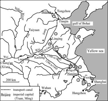
The Yuan chose Beijing for their capital, this being a more central site for their new empire than the ancient capitals of Chang’an, Luoyang and Kaifeng. Just as the Sui had been impelled to construct the first Grand Canal in the 7th century, the Mongols now saw the need to reestablish a large waterway, ideally as a more direct link from Beijing to the Yangtze basin. In 1275 a Mongol general called Bayan was fighting against the Song of the south. He began studies of a canal that would use the north portion of the Grand Canal of the Sui, but would cut directly toward the southeast from Lingqing. This canal would rejoin the arm of the Yellow River that had bifurcated from there toward the Huai since the 1190s (this is course no. 5 in Figure 8.2). Between 1280 and 1283 the Huangong and Jizhou canals were built more or less along the alignment of this arm.

The Jizhou canal takes a shortcut across the foothills of Shandong, and has 31 gates along a distance of nearly 150 kilometers (250 li). These canals make it possible to ship goods from the south up to the bifurcation of the course of the Yellow River, then on the

The Grand Canal of the Yuan and the Ming Dynasties

Figure 8.13 The Grand Canal of the Yuan and the Ming.

1: elements of the Grand Canal of the Sui (renovated between 1280 and 1290)

2: Huangong canal (1280)

3: Jizhou canal (1283, 1411)

4: Huitong canal (1289)

5: Tonghui canal (1293)

6: Jiao-Lai canal

northern course to the Gulf of Bohai from which they continue by sea to Tientsin.

Five years later (1288) the Yellow River abandons its principle course to the north of Shandong (though this branch carries some flow until 1945) and flows out to the south into the Huai, even further upstream than earlier. This course change probably motivat­ed and likely facilitated the completion of the waterway project. Indeed just one year later, in 1289, the Huitong canal – whose design had been studied by general Bayan – is completed in its turn. The totality of the project is completed in 1293 by the Tonghui canal linking the capital Beijing to Tongzhou. This canal had to have some 20 gates, for Beijing is at a higher elevation than the rest of the system. The remainder of the water­way network, whose layout follows that of the first Grand Canal of the Sui and the Song, is simply brought back into service and improved (in 1290 for the channelization of the Wei river.).

Marco Polo sojourns in the court of Kubla Khan in 1280, and probably in 1288-1290 is sent on a mission to the south of China (he returns to Italy in 1298). He writes of the city of Guazhou, at the junction of the Yangtze and the Grand Canal, as follows:

“The city is on the river, and it is there that, every year, vast quantities of rice are collected.

And, from this city, they are transported to the large city of Cambaluc (Beijing), to the court of the Great Khan, by water. But understand this is not by sea, but by rivers and lakes. [….] And I tell you that the Great Khan had these waterways between the two cities brought into service, for he had huge trenches dug, very wide and very deep, from one river to another and one lake to another, and had water transported by canals, so that it all became like one large river, and great ships go on it.”[433]

Marco Polo also speaks of the city of Jining, which is at the junction of the Huangong and Jizhou canals. He notes how the watercourses coming from the heights of Shandong are captured to supply the highest portions of the Canal:

“And I tell you further that they have a river from which they profit immensely and I will tell you how. The truth is that this large river comes from the midlands to this city of Singi Matu (Jining), and the people of the city, from this large river made two; for they sent half toward the rising sun and the other half toward the setting sun, that is to say that one goes toward Mangi (the region of the lower Yangtze) and the other toward the Catai (the region of Beijing). And I tell you truthfully that this city has such grand ships – such a large quantity of boats – that no one could believe it without having seen it. Do not take this to mean that they are large ships: they are of appropriate size for vast rivers. And I tell you that these ships carry to Catai and to Mangi such large masses of merchandise that it is a marvel… .”[434]

Starting in 1327, repeated floods cause serious famines. In 1344, the dikes break downstream of Kaifeng and are not restored until 1349. The plight of the miserable peasants of this region, along with the massive labor conscriptions necessary for the dike repairs, leads to the emergence of the Red Turbans. This secret society soon leads an insurrection against the power of the Mongols.[435]

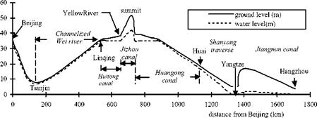
A glance at Figure 8.14 makes it easy to understand the problem of water supply to

The Grand Canal of the Yuan and the Ming Dynasties

Figure 8.14 Longitudinal profile of the Grand Canal, from a modern survey (Needham et al, 1971).

the highest portion of the Grand Canal of the Yuans, i. e. the Jizhou canal in Shandong.

This problem is not solved by the Yuan, who continue to use primarily the maritime route and in effect cut off the Shandong peninsula with the Jiao-Lai canal. It is not until the Ming regime, arising from the insurrection that chased out the Mongols in 1368, that an effective solution to this problem is developed using hydraulic works. In 1411,

165,0 people are put to work on the 200-day construction of a dam-reservoir that could assure a sufficient supply of water to maintain the supply to the Jizhou canal throughout the year. Other small reservoirs are constructed near the canal’s locks, which were also rebuilt at this time.

Under the Ming the strategy adopted for control of the Yellow River consisted in preventing any return of the course toward the north through construction of a very long dike, stretching for several hundreds of kilometers. Systems of multiple dikes delimit­ing the flood plain were also constructed. A real strategy for sediment management was put into place. This strategy combined deposition in flood-plain zones managed for this purpose with narrower channels in which the strength of the current was sufficient to prevent deposition. Starting in 1495 the course of the river was finally stabilized, as shown on course no. 7 of Figure 8.2.

Important canal rehabilitation work took place in 1528, still under the Ming, in par­ticular separating the bed of the Grand Canal from that of the Yellow River. Piracy was developing along the shores of the Sea of China at this time, rendering more indispensa­ble than ever the use of the grand artery between the south and north of the country.

It was also during this period that work was done on the Hongze lake. This lake had probably been just a natural flood plain for the southern course of the Yellow River up to then. This zone was transformed into a permanent reservoir of increased volume through construction of a large north-south dike delimiting the eastern bank of the lake over more than 30 km, in 1578.[436] An engineer called Pai Jixun led this work; he was also known for his work on control of Yellow River sediments. At the beginning of the Manchu domination (1660) this dike is extended to a total length of 67 km and its height is raised 1.5 m to attain a maximum of 7 m. The structure itself is a masonry wall whose stones are tied together by steel tendrils. The wall is about 1 m thick and supported by an earthen embankment, and rests on a foundation of piles.

In the 14th and 15th centuries the Grand Canal evolves to a configuration that is essentially the same as today. Its total length of about 1,700 km makes it the largest hydraulic project ever constructed by man. We earlier saw how travelers at the begin­ning of the 14th century had been impressed by the Grand Canal of the Yuan. Three cen­turies later another westerner embarks upon the Grand Canal. This is father Matteo Ricci, the founder of the Jesuit missions in China, who traveled from Nanjing to Beijing between September 1597 and February 1598. Being a scientist, he begins by describing the overall fluvial system:

“This river of Nanjing (the Yangtze) goes from Nanjing to the north; then, returning somewhat toward the midlands, flows with great impetuosity into the sea. [….] This is why, to be able to go by water into the royal court of Beijing, the kings of China drew a large canal from this river to another, that is called Yellow. [….] This river [….] as if in revenge for the hate that the Chinese carry to foreigners, very often spoils a large part of the kingdom through its large floods and changes its channel as it pleases, when it is filled with sand that it carries along.”[437]

This latter account reveals the isolationism that characterizes the end of the Ming Dynasty. In following sections of his treatise Matteo Ricci gives a very vivid descrip­tion of the traffic on the upper portions of the Grand Canal, as well as of passages through the flush locks. He also mentions the inclined planes on which boats are dragged using capstans. He does not mention any chamber locks.

“And, however, the multitude of vessels is so excessive that the ships, each blocking the oth­ers, are often obliged to wait several days to pass, principally in certain times when there is not enough water in the canals. To solve this, they hold back water in several places with locks of wood, which also, to serve two purposes, are installed as bridges. These locks, when the stream is full, are opened and the boats are carried by the force of the running water. And, thus, the sailors navigate from lock to lock with great difficulty and along a tiresomely long route. The work is made even more difficult since it is very infrequent that, in the narrow strait of the stream, the winds are favorable for the vessels. This is why, ordinarily one uses ropes to advance along the canal and even, it often happens that at the entrance or exit from the locks, when waves rising up like impetuous whirlwinds come to envelope the boats, they are lost in the canals drowning all those who were within. But the ships of magistrates or princi­pals are pulled against the water with machines of wood; and this happens along all the route at the expense of the King.”[438]

Reading this account, one can understand what led Chiao Wei-Ho to invent the chamber lock in the 10th century. It is more difficult to understand why this process is not used in the upper reaches of the Grand Canal of the Yuan and the Ming. Does this

The Grand Canal of the Yuan and the Ming Dynasties

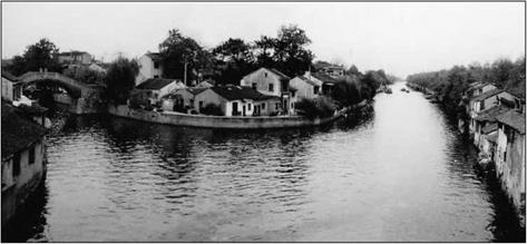
Figure 8.15 An ancient stretch of the Grand Canal (Jiangnan canal) at Wuxi (photo by the author)

perhaps mark the beginning of the decline in the spirit of innovation that will character­ize the 17th and 18th centuries?

This is a good time to note the influence of inland water transport on urbanism. Certain cities along the Grand Canal are virtual “Chinese Venices” (Figure 8.16). We can illustrate this through the Venetian Marco Polo’s description of the city of Hangzhou (Han-Tcheou). In the 13th century this city becomes the capital of the Song when they retreat to the south. With nearly one and a half million inhabitants,[439] it is also perhaps the largest city in the world (along with Baghdad before the passage of the Mongols): “It (the city of Hangzhou) is situated in such a manner that it has, on one side, a freshwater lake that is very clear, and, on the other side, an enormous river that, entering in many canals from small to large and flowing through all the districts of the city, carries all the filth, then penetrates into the lake and, from there, flows toward the ocean. This makes the air very healthy. One can visit all the city both on land and on the water. The streets and canals are long and wide, so much so that boats can navigate on them as they please. [….] No one should be surprised to see so many bridges; because I tell you that this city is entirely on the water and surrounded by water. [….] On the other side of the city is a trench that is perhaps forty milles in length, enclosing the city on that side; it is very wide and completely full of water from the aforementioned river. This was done by order of the ancient kings of the province, to be able to redirect the river each time it overflows the dikes.”[440]

Global Stability

Evaluation of a global safety factor that includes the nailed soil and the surrounding ground requires determination of the critical sliding surface. This surface may be located totally inside, totally outside, or part inside and part outside the nailed zone. Limit equilibrium methods are usually used, and the Davis method is recommended because of its simplicity and availability in the public domain (C. K. Shen et al., “Field Measurements of an Earth Support System,” Journal of the Geotechnical Division, American Society of Civil Engineers, vol. 107, no. 12, 1981). The Davis method has been modified (V. Elias and I. Juran, “Soil Nailing,” Report for FHWA, DTFH 61-85-C, 1988) to permit input of interface limit lateral shear forces obtained from pullout tests, separate geometric and strength data for each nail, facing inclination, and a ground slope at the top of the wall. The concrete facing elements (shotcrete, cast-in-place concrete, or prefabricated panels) are considered for design to be analogous to a beam or raft of a unit width equal to the nail spacing supported by the nails.

8.8.4 Contracting Practices

Although procurement and contracting practices vary among the European countries, there are some common elements that tend to distinguish European practices from those in the United States. These include (1) strong industry, academic, and government
cooperation in research and development and the introduction of new technologies; (2) a partnering approach among all parties involved in a particular project; (3) less litigation; and (4) a high level of contractor involvement in the conceptualization and design phases, as well as during construction.

In France, the contractor design-build approach appears to be dominant. For public agency work, a prequalified group of contractors are typically asked to prepare a final design and bid, based on a preliminary design prepared by the owner or the owner’s consultant. Alternative designs may also be prepared by the contractor at this time, and may be selected if they are technically and financially viable and meet the overall performance and scheduling requirements of the project. French contractors tend to be much larger and stronger than their U. S. counterparts, and the major groups tend to support significant research and development efforts. Contractor-consultant-academic – government cooperation in areas requiring major research and development is particularly well developed in France.

In Germany, public agency work is again usually bid on a conceptual or prelimi­nary design prepared by or for the agency, with the contractor required to submit a bid on the original design and also encouraged to submit any alternative design that will provide an equivalent wall at a reduced price. Ultimately, award is made for the lowest – cost responsive bid. Soil nailing in Germany requires the involvement of one of a small group of prequalified or “licensed” contractor organizations. As in France, these contractors tend to be technically and financially very strong. Private work, like public work, tends to be awarded on the basis of low bid.

Based on the European, and particularly the French, experience, two main recommen­dations are offered for encouraging the development of innovative construction methods and improving the construction performance for such methods. First, stronger and more formal government-academic-industry cooperation should be established to develop new technologies and disseminate the information in a nonproprietary manner. This should also include participating in corresponding European programs when the opportunity arises and when the information will be of mutual benefit. Second, alternative bidding, including contractor design-build alternatives, performance-oriented specifications, and the use of carefully prequalified specialty contractors, should be encouraged.

Types Of Tanks

There are many types of septic tanks in use today. Pre-cast concrete tanks are, by far, the most common. However, they are not the only type of sep­tic tank available. For this reason, let’s discuss some of the material options that are available.

Pre-cast concrete is the most popular type of septic tank. When this type of tank is installed properly and is not abused, it can last almost indefinitely. However, heavy vehicular traffic running over the tank can damage it, so this situation should be avoided.

Metal septic tanks were once prolific. There are still a great number of them in use, but new installations rarely involve a metal tank. The reason is simple, metal tends to rust out, and that’s not good for a septic tank. Some metal tanks are said to have given twenty years of good service. This may be true, but there are no guarantees that a metal tank will last even ten years. In all my years of being a contractor, I’ve never seen a metal septic tank installed. I’ve dug up old ones, but I’ve never seen a new one go in the ground.

Types Of Tanks

Types Of Tanks

I don’t have any personal experience with fiberglass septic tanks, but I can see some advantages to them. Their light weight is one nice benefit for any­one working to install the tank. Durability is another strong point in the fa­vor of fiberglass tanks. However, I’m not sure how the tanks perform under the stress of being buried. I assume that their performance is good, but again, I have no first-hand experience with them.

Wood seems like a strange material to use for the construction of a sep­tic tank, but I’ve read where it is used. The wood of choice, as I understand it,

Types Of Tanks

FIGURE 14.6 ■ Outside cleanout installed in sewer pipe and sweep-type fittings used to avoid pipe stoppages.

is redwood. I guess if you can make hot tubs and spas out of it, you can make a septic tank out of it. However, I don’t think I would be anxious to warranty a septic tank made of wood.

Подпись: been there done that Some contractors turn to creative solutions to save money, but they may be making trouble for themselves. I prefer to use proven materials to avoid problems down the road. Compared to the cost of a pre-cast septic tank, building a tank on site doesn’t make sense to me. I suggest using known products that are less likely to create warranty problems for you. Brick and block have also been used to form septic tanks. When these methods are employed, some type of parging and waterproofing must be done on the inte­rior of the vessel. Personally, i would not feel very comfortable with this type of setup. This is, again, material that I have never worked with in the creation of a septic tank, so I can’t give you much in the way of case histories.

Historical development of hydrosystem design methods

The evolution of hydrosystem design methods can be roughly classified into four stages: (1) historical event-based design, (2) return-period design, (3) conven­tional risk-based design, and (4) optimal risk-based design with consideration given to a variety of uncertainties.

Historical event-based design. In the design of hydrosystem infrastructures and the establishment of land-use management practices to prevent and/or reduce damages resulting from natural disasters, the risk (damage) assessment typ­ically has been implicit. The earliest structures and land-use management approaches for flood protection were designed or established on the basis of their ability to withstand previous disastrous floods. For example, Chow (1962) noted that the Dun waterway table used to design railroad bridges in the early 1900s was primarily determined from channel areas corresponding to high – water marks studied during and after floods. Thus previous large floods of un­known frequency could pass through the designed bridges safely. Also, after a devastating flood on the Mississippi River in 1790, a homeowner in Saint Genieve, Missouri, rebuilt his house outside the boundary of that flood. Similar rules were applied in the design of coastal-protection works in The Netherlands at the time the Zuiderzee was closed (1927-1932) (Vrijling, 1993).

Rules based on previous experience work well in some cases. For example, the house in Missouri was not flooded until the 1993 flood on the Mississippi River, and the Zuiderzee protection works survived the 1953 storm that devastated the southwestern part of The Netherlands. However, in most cases these meth­ods are inadequate because human experience with floods and other natural hazards do not include a broad enough range of events. As noted by Vrijling (1993), “One is always one step behind when a policy is only based on historical facts.”

Return-period design. In the early part of the twentieth century, the concept of frequency analysis began to emerge as a method to extend limited data on extreme events to probabilistically estimate the magnitude of rarely occur­ring events. Frequency analysis of observed events is a key aspect of meteoro – logic, hydrologic, and seismic hazard analyses. Thus, using frequency-analysis methods, it is possible to estimate events with magnitudes beyond those that have been observed. This necessitates the selection of a societally acceptable hazard frequency (see Sec. 8.3.6).

Using the return-period design approach, a hydraulic engineer first deter­mines the design discharge from a frequency-discharge relationship by select­ing an appropriate design frequency or return period. The design discharge then is used to determine the size and layout of the hydrosystem that has a satisfactory hydraulic performance. In the return-period design method, selec­tion of the design return period is crucial to the design. Once the design return period is determined, it remains fixed throughout the whole design process. In the past, the design return period was selected subjectively on the basis of an in­dividual’s experience or the societally acceptable hazard frequency (Sec. 8.3.6). Selection of the design return period is a complex procedure that involves con­siderations of economic, social, legal, and other factors. However, the procedure does not account for these factors explicitly.

Conventional risk-based design. Risk-based design is a procedure that evaluates among alternatives by considering the tradeoff between the investment cost and the expected economic losses due to failures. Specifically, the conventional risk- based design considers the inherent hydrologic uncertainty in calculation of the expected economic losses. In the risk-based design procedure, the design return period is a decision variable instead of being a preselected design parameter value, as with the return-period design procedure.

The concept of risk-based design has been recognized for many years. As early as 1936, Congress passed the Flood Control Act (U. S. Statutes 1570), in which consideration of failure consequences in the design procedure was advocated. The economic risks or the expected flood losses were not considered explicitly until the early 1960s. Pritchett’s work (1964) was one of the early attempts to apply the risk-based hydraulic design concept to highway culverts. At four ac­tual locations, Pritchett calculated the investment costs and expected flood dam­age costs on an annual basis for several design alternatives, among which the most economical one was selected. The results indicated that a more economical solution could be reached by selecting smaller culvert sizes compared with the

traditional return-period method used by the California Division of Highways. The conventional approach has been applied to the design of highway drainage structures such as culverts (Young et al., 1974; Corry et al., 1980) and bridges (Schneider and Wilson, 1980). Inherent randomness of hydrologic processes is integrated with reliability analysis in seismic, structural, and geotechnical aspects in the design of new dams (Pate-Cornell and Tagaras, 1986) and eval­uation of alternatives for rehabilitating existing dams (McCann et al., 1984; Bureau of Reclamation, 1986; National Research Council, 1983).

Risk-based design considering other uncertainties. In the conventional risk-based hydraulic design procedure, economic risks are calculated considering only the randomness of hydrologic events. In reality, there are various types of un­certainties, as described in Sec. 1.2, in a hydrosystem infrastructure design. Advances have been made to incorporate other aspects of uncertainty in the design of various hydrosystem infrastructures. For example, both hydrologic and hydraulic uncertainties were considered in the design of highway drainage structures (Mays, 1979; Tung and Mays, 1980, 1982; Tung and Bao, 1990), storm sewer systems (Yen and Ang, 1971; Yen and Jun, 1984; Tang and Yen, 1972; Tang et al., 1975, 1976), levee systems (Tung and Mays, 1981b), riprap design of stable channels (Tung, 1994), and river diversion (Afshar et al., 1994). Inherent hydrologic uncertainty, along with parameter and model uncertain­ties, was considered in design of levee systems (Wood, 1977; Bodo and Unny, 1976). Economic uncertainty, along with hydrologic and hydraulic uncertain­ties, has been considered in flood-damage-reduction projects (U. S. Army Corps of Engineers, 1996).

Basic concept

The basic concept of risk-based design is shown schematically in Fig. 8.9. The risk function accounting for the uncertainties of various factors can be obtained using the reliability computation procedures described in earlier chapters. Al­ternatively, the risk function can account for the potential undesirable conse­quences associated with the failure of hydrosystem infrastructures. For sim­plicity, only the tangible damage cost is presented herein.

Risk costs associated with the failure of a hydrosystem infrastructure cannot be predicted accurately from year to year. A practical way is to quantify risk cost using an expected value on an annual basis. The total annual expected cost (TAEC) is the sum of the annual installation cost and annual expected damage cost, which can be expressed mathematically as

TAEC(x) = FC(x) x CRF + E(Dx) (8.29)

where FC is the first or total installation cost, which is the function of decision vector x defined by the size and configuration of the hydraulic structure, E(D x) is the annual expected damage cost associated with structural failure, and CRF is the capital recovery factor, which brings the present worth of the installation costs to an annual basis and can be computed as

CRF = (1 + i} T~T 1 (8.30)

i(1 + i)1

Annual cost

Basic concept

Figure 8.9 Schematic diagram of optimal risk-based design.

with T and і being the expected service life of the structure and the interest rate, respectively.

In practice, the optimal risk-based design determines the optimal structural size, configuration, and operation such that the annual total expected cost is minimized. Referring to Fig. 8.6, as the structural size increases, the annual in­stallation cost increases, whereas the annual expected damage cost associated with the failure decreases. The optimal risk-based design procedure attempts to determine the lowest point on the total annual expected cost curve. Mathe­matically, the optimal risk-based design problem can be stated as

Minimize TAEC(x) = FC(x) x CRF + E(Dx) (8.31a)

subject to gi (x) = 0 і = 1,2,…, m (8.31b)

where gi(x) = 0, і = 1, 2,…, m, are constraints representing the design speci­fications that must be satisfied.

In general, the solution to Eqs. (8.31a-b) could be acquired through the use of appropriate optimization algorithms. The selection or development of the so­lution algorithm is largely problem-specific, depending on the characteristics of the problem to be optimized. Section 8.4 describes an application of the optimal risk-based design to pipe culverts for roadway drainage.