Evaluations of annual expected flood damage cost

In risk-based and optimal risk-based designs of hydrosystem infrastructures, the thrust of the exercise, after uncertainty and risk analyses are performed, is to evaluate E( Dx) as the function of the probability density functions (PDFs) of loading and resistance, damage function, and the types of uncertainty considered.

Подпись: E1( Dx) Подпись: qt Подпись: D(qqC) fq(q) dq Подпись: (8.32)

Conventional approach. In conventional risk-based design, where only inher­ent hydrologic uncertainty is considered, the structural size x and its corre­sponding flow-carrying capacity qc, in general, have a one-to-one monotonically increasing relationship. Consequently, the design variables x alternatively can be expressed in terms of design discharge of the hydrosystem infrastructure. The annual expected damage cost, in the conventional risk-based hydraulic design, can be computed as

where qt is the deterministic flow capacity of a hydraulic structure subject to random floods following a PDF fq(q), and D(qqC) is the damage function corresponding to the flood magnitude of q and hydraulic structural capacity qt. A graphic representation of Eq. (8.32) is shown in Fig. 8.10, and E1(Dx) corresponds to the shaded area under the damage-frequency curve. Owing to the complexity of the damage function and the form of the PDF of floods, the analytical integration of Eq. (8.31), in most real-life applications, is difficult, if not impossible. Hence the evaluation of annual expected damage cost by Eq. (8.32) is done numerically.

Evaluations of annual expected flood damage cost

Evaluations of annual expected flood damage cost

Damage (D)

Figure 8.10 Computation of annual expected damage.


Note that Eq. (8.32) considers only the inherent hydrologic uncertainty owing to the random occurrence of flood events, represented by the PDF fq(q). It does not consider hydraulic and economic uncertainties. Furthermore, a perfect knowledge about the probability distribution of flood flow is assumed. This is generally not the case in reality.

Incorporation of hydraulic uncertainties. As described in Sec. 1.2, uncertainties also exist in the process of hydraulic computations for determining the flow­carrying capacity of the hydraulic structure. In other words, qc is a quantity subject to uncertainty. From the uncertainty analysis of qc (Tung and Yen, 2005), the statistical properties of qc can be estimated. Hence, to incorporate uncertainty feature of qc into the risk-based design, the annual expected dam­age can be calculated as

Подпись: О gqc(qc )dqc = Ei( Dqc )gqc(qc )dqc 0 f СО Г /* СО

E2( D) = D(qqc) fq(q)dq

in which gqc(qc) is the PDF of random flow-carrying capacity qc. Again, in prac­tical problems, the annual expected damage estimated by Eq. (8.33) would have to evaluated through the use of appropriate numerical integration schemes.

Considering hydrologic inherent and parameter uncertainties. Since the occurrence of streamflow is random by nature, the statistical properties such as the mean, standard deviation, and skewness coefficient of the distribution calculated from a finite sample are also subject to sampling errors. In hydrologic frequency analysis, a commonly used frequency equation (Eq. 3.5) for determining the magnitude of a hydrologic event, say, a flood, of a specified return period T years is

qT = Mq + Kt Oq (8.34)

in which qT is the magnitude of the hydrologic event of the T year, Mq and oq are the population mean and standard deviation of floods, respectively, and Kt is the frequency factor depending on the skewness coefficient and distribution of the flood event.

Consider floods being the hydrologic event that could potentially cause the failure of the hydraulic structure. Owing to the uncertainty associated with the estimated values of Mq, oq, and Kt in Eq. (8.34), the flood magnitude of a specified return period qT is also a random variable associated with its prob­ability distribution (see Fig. 8.11) instead of being a single-valued quantity presented by its “average,” as commonly done in practice. Section 3.8 describes the sample distributions for some of the probability distributions frequently

Evaluations of annual expected flood damage cost

Figure 8.11 Schematic sketch of sampling distribution of flood magnitude estimator.

used in hydrologic flood frequency analysis. Hence there is an expected damage corresponding to the T-year flood magnitude that can be expressed as

n TO

E(Dt qC) = / D(qr q*c)hqT (qr )dqT (8.35)

■hn

Подпись: E2( Dq*)
Подпись: D(qr qc)hqr (qr q) dqr Подпись: fq (q) dq Подпись: (8.36)

where E(Dt q*) is the expected damage corresponding to a T-year flood given a known flow capacity of the hydraulic structure q*, hqT (qT) is the sampling PDF of the flood magnitude estimator of a T-year return period, and qT is the dummy variable for a T-year flood. Equation (8.35) represents an integration of flood damage over the shaded area associated with the sample distribution of a T-year flood. To combine the inherent hydrologic uncertainty, represented by the PDF of annual flood fq(q), and the hydrologic parameter uncertainty, represented by the sampling PDF for a flood sample of a given return period hqT (qT), the annual expected damage cost can be written as

Подпись: qq

Incorporation of hydrologic inherent and parameter and hydraulic uncertainties. To

Подпись: E4( D) Evaluations of annual expected flood damage cost Evaluations of annual expected flood damage cost Evaluations of annual expected flood damage cost

include hydrologic inherent and parameter uncertainties along with the hy­draulic uncertainty associated with the flow-carrying capacity, the annual expected damage cost can be written as

Summary. Based on the preceding formulations for computing annual expected damage in risk-based design of hydraulic structures, one realizes that the math­ematical complexity increases as more uncertainties are considered. However, to obtain an accurate estimation of annual expected damage associated with the structural failure would require the consideration of all uncertainties, if such can be practically accomplished. Otherwise, the annual expected damage would, in most cases, be underestimated, leading to inaccurate optimal design. In an application to flood levee design (Tung, 1987), numerical investigations indicate that without providing a full account of uncertainties in the analysis, the resulting annual expected damage is significantly underestimated, even with a 75-year-long flood record.

Electrical

Electromagnetic Fields

Electric and magnetic fields are commonly discussed as if they were a single entity termed electromagnetic fields or EMFs. In fact, the two phenomena, although interrelated, are distinctly different and they will be discussed separately in this chapter. Chart 16.1 presents a comparison of the two.

Magnetic Fields

Basic Home Wiring and Net Current

Although the relationship between human health and elevated fields remains contro­versial, there are definite safety concerns as­sociated with wiring techniques that cause magnetic fields. In recognition of such haz­ards, the National Electrical Code has man­dated safer wiring. Your electrician may be puzzled if you declare that you want a home free of all elevated magnetic fields, but if you say you want a home free of net current in compliance with the electrical code, you are
saying the same thing in a language electri­cians understand.

Most household wiring consists of no-volt lines. If you were to peel back the outer insu­lating plastic on a piece of Romex, the most common wiring used, three strands would be revealed — one black, one white, and a third either green or bare copper. The black strand is referred to as the hot wire because it draws electricity from the breaker box or panel and delivers it to light fixtures and appliances. The white wire, called the neutral, returns the elec­tricity to the panel after it is used. The green or bare copper wire is the ground wire. Under normal conditions, it does not carry electric­ity. However, if a malfunction such as a short occurs, it serves as a fail-safe protective de­vice, carrying power back to the ground un­til the breaker is tripped and the power to the faulty circuit is cut off, thereby helping to pre­vent shock and electrocution.

When the electrical system is functioning as it should, the amount of electricity flowing

out to an appliance through the hot wire is equal to the amount of electricity flowing back through the neutral wire. This equal and op­posite flow of current through the wires cre­ates a net current that cancels to zero, which is the desired condition. When, for various rea­sons, unequal supply and return currents are unable to cancel each other out, a net current is present and a magnetic field is created.

A second condition that creates net cur­rent with associated magnetic fields occurs when the neutral and hot wires are separated by distance. When Romex wiring is used, the hot and neutral wires run adjacent to one an­other inside the plastic insulating sheathing, allowing them to cancel each other out. In an older wiring system known as knob and tube,

the hot and neutral wires were run on sepa­rate studs. The distance between the wires re­sulted in an uncancelled magnetic field. There was also no grounding. Although now prohib­ited by code, this dangerous system of wiring, along with its associated elevated magnetic fields, is still found in many older homes.

The National Electrical Code prohibits the production of net current. This requirement should protect people from elevated mag­netic fields as well. Unfortunately, subtle code violations resulting in the production of net current frequently occur, not only causing el­evated magnetic fields but also increasing the risk of fire and electrocution.

We have identified several commonly used wiring techniques that create very high

Chart 16.1: Comparison of Electric and Magnetic Fields

Electric fields

Magnetic fields

Flow in straight lines in all directions from the source unless conductors attract them

Radiate out from the source, flowing in loops

Can be easily shielded

Difficult and expensive to shield {even lead is not effective)

Attracted by conductors such as metal, saltwater bodies, and people

Penetrate all normal building materials

Present when switches for machinery are off or on

Occur only when appliances are switched on and current is flowing

Not widely recognized presently in conventional circles as a health threat

Safe-exposure limits not regulated by the US gov­ernment, though Sweden has set limits

Reportedly affect the nervous system and can cause insomnia, anxiety, depression, aggressive behavior, and a higher risk of leukemia1

Reportedly affect cellular function and have been statistically linked in some studies with increased cancer cell growth rate, Alzheimer’s, miscarriage, and birth defects, while some sensitive individuals report physical reactions

Electrical code permits but does not mandate wiring for reduced electric fields

Electrical code offers protection against exposure to magnetic fields produced by wiring in the structure, with some exceptions

Proper use of electric field meters requires expertise

Easily measured with a gaussmeter

magnetic fields. Although these techniques are considered to be code violations by most code interpreters because they create net current, they often go unnoticed by building inspec­tors. Case studies 16.1 and 16.2 are accounts of such occurrences. Following are specifications for wiring techniques and inspections for pre­venting and detecting elevated magnetic fields in wiring:

• All wiring shall be performed in strict accordance with the National Electrical Code.

• The ganging of neutral wires from differ­ent branch circuits is prohibited.

• Hot and neutral wires must be bundled together, as in Romex. Separate wires fol­lowing separate paths are prohibited.

• Bonding screws shall be removed from the neutral bus of all subpanels per manu­facturer s instructions.

• When wiring a half-switch outlet using two separate breakers for each half of the outlet, the two neutral wires must not make electrical contact. This is accom­plished by breaking off the prescored con­ductive tabs between the two sections of the outlet per manufacturer s instructions.

• Neutral wires on half-switched outlets shall not be mixed. They shall remain paired with corresponding hot wires.

• When wiring enters an electrical box from more than one circuit, care must be taken to ensure that the wires from the differ­ent circuits are isolated from one another so that electricity return paths are not shared. This can be done by installing wir­ing so that all wiring entering an electrical box is from the same circuit.

• At the time of the final electrical instal­

lation, and in the presence of the general contractor, architect, or owner, the electri­cian shall apply a minimum load of three amps to the distal end of each electrical circuit. The home shall be inspected un­der load using a gaussmeter. Any elevated ambient magnetic fields greater than 0.5 milligauss will indicate the presence of net current. These measurements should be taken about a foot away from switches or outlets as the levels right at the switch or outlet will generally be greater than 0.5.

* It is the responsibility of the electrical contractor to locate and eliminate net cur­rent caused by the electrical installation.

• The home shall be reinspected for any net current resulting from the work of other trades in the completed building.

An inspection should be performed after elec­trical installation but before wall surfacing is installed so that any net current resulting from errors in the electrical installation can be determined and easily remedied. The elec­trician should be responsible for correcting these errors. Reinspecting after the surfacing materials are installed will help determine if other trades have caused damage to the elec­trical system. For example, a nail might pene­trate the wiring and cause electrical problems. This damage would not be the fault of the elec­trician, but the electrician would need to cor­rect it.

Nail the casing to the jambs

Nailing trim around doors and windows can be difficult when the wall extends past the jamb.

If drywall edges protrude just a little, they can usually be knocked back enough by hitting them gently with a hammer. Just make sure the casing will completely cover the flattened, compressed drywall.

Sometimes, I start by installing door casing inside a closet, where people won’t readily notice mistakes. Think of it as a warm-up exercise. Begin by nailing a piece of side casing first, holding it to the reveal marks. (Other people start with the head casing first.) If you’re nailing
the casing by hand, drive a pair of nails at the top and then about every 16 in. down the casing. Drive 4d nails through the trim and into the jamb, and drive 6d nails through the thicker part of the trim and into the wall frame. A pneumatic finish nailer makes this job much easier, and you won’t have to use different size nails.

Next comes the head casing. Check the joint between the head and the side casing. If it looks good, add a bit of glue to the ends of the two pieces, then nail the head casing to the wall along the horizontal reveal line (see the photo above). If the joint is open a little, cut the miter again and fine-tune the angle of the chopsaw, if necessary, to get a better fit. If the joint is open more than a little, cut another headpiece; start a little long and make sure you have the angle right before cutting it to length. If all else fails, fill the joint with putty before painting. Repeat this process for the second piece of side casing.

Nail the casing to the jambsПодпись:Подпись:Nail the casing to the jambs

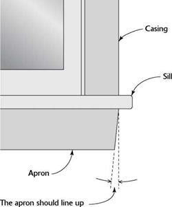
Подпись: Casing installed around an attic staircase or access hole can be cut and nailed in the same way. The only difference is that you’ll have miter joints at all four corners. Install the window aprons Just as you’d imagine, the piece of trim called an apron is installed beneath the windowsill. It covers the joint between the drywall and the sill and is usually cut from casing stock. Nail it in place with its wide edge up against the sill to support it. The apron does not run the full length of the sill. If the window sides are covered with drywall, cut the apron 2 in. longer than the window opening. For windows with wood jambs and casing, the apron should line up with the outside edges of the casing on both sides of the window. You can cut the apron square or give it a slight back-cut of about 6 degrees (see the illustration at right). Then nail the apron directly below the windowsill (see the photo below).
Подпись: INSTALLING A WINDOW APRON

STEP 4 INSTALL THE CABINETS I

Подпись:Nail the casing to the jambs
folks with special needs. A local woodworker in his small shop builds the cabinets we use in Habitat houses here on the Oregon coast. They are made from pine or birch and particleboard. Although simple in style, they’re also beautiful and, thankfully, rather inexpensive.

Kitchen and bath cabinets can be installed any time after painting. Base cabinets should be installed after the underlayment and the vinyl
floor are in place. That makes it much easier for the vinyl-floor installer. Just be careful not to mar the floor while installing the cabinets. Baseboard trim is installed after the cabinets because it butts into the base cabinets.

Today’s kitchens are filled with many appli­ances, such as a refrigerator, stove, microwave oven, garbage compactor, and dishwasher. Most appliance suppliers are more than happy to look at your house plans and help you design a kitchen in which every cabinet and appliance fits into its allotted space. Once you settle on a cabinet style, you can choose different sections—one for dishes, one for pans, one for utensils, and so on. After cabinets are delivered to the job site, they are installed one section at a time.

Air Filtration

The addition of filters to ventilation and forced-air heating and cooling systems allows for greater control of air quality. As discussed above, indoor air is often too polluted to prop­erly nourish occupants. The first line of defense against such pollutants is to provide an ample supply of fresh outdoor air through ventila­tion. Unfortunately, “fresh” air, although con­siderably cleaner in most cases than indoor air, often contains allergens in the form of molds, pollens, and manufactured pollutants,

Type

Purpose

How it works

Advantages

Disadvantages

Comments

Natural

ventilation

To bring fresh air into the home and exhaust stale air

Takes advantage of natural air pat­terns. Strategically placed openings encourage fresh air to move diagonally through the space, entering low and exiting high.

• Quiet

• Free

• Maintenance-free

• Does not require energy to operate

• Can be drafty and create greater heating/cooling load

• Air cannot be filtered

• Allows for only minimal control

• Requires high level of occupant participation

• Suitable as sole means of ventila­tion throughout the year only in very temperate climates

• Outdoor air must be clean

This strategy works best in mild climates and can be enhanced through various roof-ventilation techniques.

Exhaust fans

To remove local­ized pollution at the point of generation, primar­ily in kitchens and baths

Stale and moisture­laden air is sucked out of the house at the point of generation, using a powerful fan.

• Pollution is quickly removed before the rest of the home is affected

• Can depressurize home, causing infiltration and possible back – drafting

It is important to supply replace­ment air when fans are in operation. Exhaust fans are required by code in bathrooms and laundry rooms without operable windows.

Supply fans

To provide fresh air

A fan blows fresh outside air into the home, creating positive pressuriza­tion that forces stale air out.

• Inexpensive

• Pressurization of home prevents contaminants from infiltrating from outdoors

• Cold drafts around fan in winter

• Pressurization can cause hidden moisture prob­lems as humid air is forced through wall openings and then con­denses

Adequate and strategically placed vents are required to exhaust air.

This is a good strat­egy for venting a basement.

Supply fans are not suitable for dispel­ling kitchen – and bath-generated pollution.

Type

Purpose

How it works

Advantages

Disadvantages

Comments

Balanced

mechanical

ventilation

To provide fresh air and exhaust stale air while control­ling pressurization

A set of fans brings in fresh air through intake and distributes it, then exhausts stale air to the exterior.

• Provides balanced pres­surization

• Comes equipped with, or can be adapted for, various filtration strategies

• Does not moder­ate temperature or humidity of incoming air

• Can be noisy

• Relatively small fans are standard and are insuf­ficient to handle large amounts of gas filtration

Air-to-air heat exchange or HRV (heat recovery ventilator)

To supply fresh outdoor air into the home while exhausting stale air and maintaining indoor tempera­tures

Incoming fresh air passes through a series of chambers adjacent to outgo­ing exhaust air. Heat, but not air, is transferred.

• Reduces heating and cooling costs by recovering 60 to 80% of heat

• Chambers can be made of paper, which collects dirt, or plastic, which can outgas; choose one with metal chambers

• More costly initially than other balanced ventilators

• Causes conden­sation; must be maintained to remain mold-free

Most effective for tight homes in cold climates. Energy re­covery ventilators (ERVs) also recover humidity VenMar Ventila­tion, Inc.

Fresh-air intake incorporated into forced-air system

To provide fresh air when the central forced-air system is operating

A 3" to 6" metal pipe with damper valve provides fresh air into the furnace supply stream.

• Inexpensive to retrofit

•Ventilation supply air is preheated or precooled

• Makes use of existing ductwork for distribution

• Creates slight positive pressur­ization and can compensate for air lost through leaky ducts

• Operates only during heating or cooling season

• Depends on a well-maintained heating and cooling system to deliver good – quality air

Screen all intake pipes to prevent rodent infestation.

including exhaust fumes, smoke, and pesti­cides. When your immediate surroundings are less than perfect, you may wish to incorpo­rate some form of filtration into your home.

Home ventilation systems can easily be adapted to filter large particles like pollen and mold spores. However, most home ventilation systems are not equipped with very powerful fans and therefore cannot handle the air re­sistance created by some of the more efficient filtration methods, especially those designed to remove gases. Consequently, whole-house filtration is often more successfully combined with the forced-air distribution system. Stan­dard filters used with most forced-air systems are designed primarily to prevent large parti­cles from harming the motor, and are insuf­ficient to effectively filter out small particles injurious to human health. Most forced-air equipment must be adapted to receive ad­ditional filtration systems. When equipped with good filters, a forced-air system will not only clean fresh intake air but also continue to clean air as it recirculates.

Filter efficiency rating systems such as the “dust spot” and “arrestance” systems have been developed by filter manufacturers to provide information about the ability of a filter to re­move large particles from the airstream. This information is of limited use when evaluating filter effectiveness for removing small parti­cles of less than 5 microns, which can be the most damaging to health. In 1999, the Ameri­can Society of Heating, Refrigeration and Air Conditioning Engineers published a new fil­ter rating system that goes by the acronym MERV. This stands for Minimum Efficiency Reporting Value and is a much better way of rating the ability of filters to remove small particles. The system currently rates filters on a scale of 1 to 16, with the higher number ratings representing filters that can remove smaller particles. Although they are currently not rated by the MERV system, a HEPA filter would likely rate a 17 or higher.

Adequate MERV filters are currently avail­able that will fit into a standard furnace filter slot. For example, a MERV 8 filter is rated to remove greater than 70 percent of particles in the 3- to 10-micron range. This will remove most, but not all, mold spores and dust and should be considered as a much better alter­native to the standard fibrous furnace filter. The Filtrete Ultra Allergen Reduction Filter #1250 is a MERV 11 filter (removes 65 to 80 percent of 1- to 3-micron particles) manufac­tured by 3M. It is commonly available at Lowes and Home Depot and will also fit in standard і-inch furnace-filter slots.

While higher MERV-rated filters as well as HEPA systems are available, these more effi­cient filters tend to create more resistance, re­quiring a much larger filter to allow air to flow through them. They do not fit into or work well with standard HVAC systems. Note that when changing from a standard furnace filter to a more efficient filter it is important to replace it after one months use before going to the reg­ular three-month maintenance schedule rec­ommended by the manufacturers because the filter will be overworked when first installed in a dirty environment. If the new type of fil­ter continues to clog too quickly, there maybe a larger than normal dust load in the building. John has observed this when an air path to the attic or crawlspace exists that pulls dirt or in­sulation fibers into the system.

Most mechanical filters that remove par­ticles by filtration actually become more effi­cient as air flows through them. They remove particles as a sieve does. As the filter loads, the airflow slows and smaller particles can then be removed. The filter must be replaced be­fore airflow is impeded. Electrostatic filters don’t do as good a job of removing particles when they get dirty and must be cleaned often to achieve the manufacturer’s stated MERV ratings.

Further Reading

Bower, John. Understanding Ventilation: How to De­sign, Select and Install Residential Ventilation Sys­tems. The Healthy House Institute, 1995.

Mazria, Edward. The Passive Solar Energy Book. Rodale Press, 1979.

Chart 15.3: MERV Ratings Compared to Other Filter Ratings

MERV

Particle size range

Test

Particle size range, pm

Applications

3 to 10 pm

1 to 3 pm

.3 to 1 pm

Arrestance

Dust spot

1

<20%

<65%

<20%

>10

• Typical residential filters

• Pollen, dust mites

2

<20%

65-70%

<20%

3

<20%

70-75%

<20%

4

<20%

>75%

<20%

5

20-35%

80-85%

<20%

3.0-10

■ 1" residential pleated filter • Pollen, dust, dust mites, most molds, most spores

6

35-50%

>90%

<20%

7

50-70%

>90%

20-25%

8

>70%

>95%

25-30%

9

>85%

<50%

>95%

40-45%

1.0-3.0

• Moderate efficiency residen­tial pleated filter (some may need furnace modification for installation)

• All of above and Legionella

10

>85%

50-65%

>95%

50-55%

11

>85%

65-80%

>98%

60-65%

12

>90%

>80%

>98%

70-75%

13

>90%

>90%

<75%

>98%

80-90%

0.3-1.0

• Specialty filter (usually need furnace modification for installation)

• All of above and smoke, bacteria

14

>90%

>90%

75-85%

>98%

90-95%

15

>90%

>90%

85-95%

>98%

-95%

16

>95%

>95%

>95%

>98%

>95%

Filter type

Purpose

How it works

Efficiency

Advantages

Disadvantages

Comments

Standard furnace filter, MERV

1-4

Filters out large particulate mat­ter to safeguard the motor, not the inhabitants

A coarse,

1 "-thick filter traps large particles.

Removes less than 20% of particulate matter; does not significantly remove small particles

* Inexpensive

• Easy to change

* Indoor air quality not significantly improved

* Does not remove signifi­cant levels of mold spores

Can easily be replaced with 1" pleated panel filter, which will raise efficiency to MERV 6-11

Medium efficiency extended surface (pleated panel) filter, MERV 6-11

Particulate filter

Air is strained through a pleat­ed (extended surface area) filter that main­tains airflow.

Removes 20­70% of particu­late matter

• Relatively inexpensive

• Sufficient for most general filtration

• Airflow resis­tance can be low enough to use with most HVAC ventila­tion systems

• Removes many mold spores

• Filtration is inadequate for very polluted environments and/or very sensitive people

• Does not filter out gaseous pollution

Many are now available that will work with standard HVAC systems.

Media filters become more efficient with time as pores become smaller, but air resistance increases.

HERA (high efficiency particulate air) filter

Particulate filter

Polyester or fiberglass fibers are bound with synthetic resins, creating a medium with extremely small pores.

Removes over 99.97% of par­ticulate matter at 0.3 microns

• Can remove minute particles for extremely clean air – Can remove cigarette smoke and almost all mold spores

• High airflow resistance requires pow­erful fan

• Expensive

• May require custom design

• Does not filter out gaseous pollution such as VOCs

Not commonly used in residen­tial filtration.

A carbon post­filter will help eliminate odor generated by the HEPA filter. An inexpen­sive, frequently changed prefil­ter will extend the life of the HEPA filter.

Filter type

Purpose

How it works

Efficiency

Advantages

Disadvantages

Comments

Electro­

static

precipitator

(ionizer)

Particulate

precipitator

Mechanism is mounted to ductwork, which statically charges dust. Dust is collected at oppositely charged plates in a filter.

Removes 90% of particulate mat­ter when clean

* No resistance to airflow

* Efficient when clean

* Does not re­quire replace­ment

• Must be adapted for residential use

• Ozone is produced as byproduct of high voltage

• Relatively expensive

• Does not filter out gaseous pollution

• Efficient only when clean

• Generates EMFs

Plates must be cleaned frequently.

Electrostat­ic air filter (passive)

Particulate filter

Electrostatic charge is gener­ated by friction as air moves through special media.

Removes 10 to 15% of particulate matter

• Good for large mold spores and pollen

• No customiza­tion required on some filters used with HVAC

• Inexpensive (washable/ reusable)

• Not efficient for capturing small particles

• Limited ef­ficiency

• Does not filter out gaseous pollution

• Requires fre­quent cleaning to maintain filter efficiency

May be sub­stituted for standard furnace filters.

An inexpensive way to relieve pollen and mold allergies. Medium effi­ciency extended surface (pleated panel) filters are making these obsolete.

TFP (turbu­lent flow precipita­tor)

Particulate

precipitator

Turbulent airstream "drops" particles into collection space, where there is no airflow.

Manufacturer claims 100% removal of par­ticulate matter

• No resistance to airflow

• Can be used with ventilator

•Very low main­tenance.

• Does not filter gaseous pol­lution

Actual perfor­mance varies widely.

Filter type

Purpose

How it works

Efficiency

Advantages

Disadvantages

Comments

Partial by­pass filter

Absorption of gaseous pollut­ants

Granules of ab­sorptive material are held in place and separated by a metallic grid. Some air passes through the medium and some flows past unrestricted.

Efficiency varies widely based on amount of air that bypasses the filter

• Allows some air to flow through, thereby cut­ting down air resistance and requiring less powerful fan

• Not suitable where air is highly polluted

• Not suitable in ventilator

Works in con­junction with HVAC, where the same air is repeatedly run through the filter.

Activated

carbon

filter

Adsorption of gaseous pol­lutants (not for particles)

Gases cling to many-faceted carbon granules.

Varies

• Effectively removes gases with high mo­lecular weight

• Offered in standard fur­nace sizes for low-pollution situations

• Does not remove certain lightweight pollutants such as formalde­hyde or carbon monoxide

• Filters become contaminated with use and can release pollutants if not changed

Can be treated to remove more gases.

Must be changed regularly per manufacturer’s recommenda­tions.

Activated

alumina

Adsorption and transformation of gaseous pol­lutants (not for particles)

Activated alumina is impregnated with potassium permanganate. It acts as a cata­lyst in changing the chemical composition of harmful gases and also acts through adsorp­tion.

Varies

• Will remove gases not removed by carbon, includ­ing formalde­hyde

■ Lasts longer than carbon

• Not as adsorp­tive as carbon

• More expen­sive than carbon

Activated alu­mina changes color when depleted.

Air Filtration

Ventilation

Until the 1960s, ventilation in homes occurred naturally, obviating the need for intentional ventilation systems. Homes were loosely built, allowing enough outside air to make its way through the home to keep it fresh. By some ac­counts, this loose construction contributed to as many as three to four air exchanges per hour. Although there were ample air exchanges, there was also an unacceptable amount of en­ergy required to run such a home, and uncon­trolled ventilation through air leakage can cause serious harm to a building. Currently, with energy-efficient construction, much of the unintentional air exchange has been elim­inated. However, while homes were built of more natural, nonpolluting materials in the past, in recent years indoor air has become at least five to ten times more polluted than out­door air and it is often too polluted for opti­mal health. Although minimum air-exchange rates are enforced for commercial structures, this is generally not the case for residential construction, except where exhaust fans are mandated.

Like many other components essential to health, ventilation is considered an “extra” in standard construction. The American Soci­ety for Heating, Refrigeration, and Air Con­ditioning Engineers (ASHRAE) has set a stan­dard of.35 air exchanges per hour, or 15 cubic feet per minute per resident, for residential ventilation. Although this may be sufficient to dispel pollutants created by human activ­ity, it may not be enough to dispel the chem­ical pollution generated by standard con­struction or the thousands of other chemicals introduced into homes through furnishings, clothing, cleaning products, cosmetics, and other scented products. ASHRAE determines its requirements based on the level at which 80 percent of a test population feels comfort­able. It should be noted that it is quite possible to feel comfortable in environments that are polluted enough to be detrimental to health. The human body has the ability to become ac­customed to harmful chemicals, much as one might adapt over time to the toxic effects of tobacco smoke. Whether or not the ASHRAE standard is sufficient to meet health require­ments is irrelevant because in fact most homes are not equipped with ventilation other than spot exhaust fans and do not meet the ASHRAE recommendations.

With tight construction, ventilation strate­gies are necessary in a healthy home to ensure fresh air and dispel odors from everyday liv­ing. Care should be taken to locate the fresh – air supply away from exhaust-air piping and in the best location for receiving an unpol­luted airstream.

. The Bright Future of

Подпись: ■ BY SEAN GROOM. The Bright Future of. The Bright Future of

Подпись: Small, powerful, and efficient. Now that they produce white light appropriate for residential settings, LEDs grouped together in a bulb pack enough punch that this 8w LED from Nexxus™ can replace a 75w PAR30 incandescent bulb.

Lighting

A

lthough still a relatively small slice of the incandescent-dominated light­ing market, energy-efficient compact fluo – rescents (CFLs) and light-emitting diodes (LEDs) have gained traction over the past few years, thanks to green-building pro­grams and some progressive local energy codes. They’re about to get a real boost.

The Energy Independence and Security Act (EISA) of 2007 soon will limit the number of watts a bulb can consume for a given number of lumens, a measure of light output. The legislation takes effect Jan. 1, 2012, when the luminary equivalent of today’s 100w incan-

P


. The Bright Future of. The Bright Future of

Подпись:. The Bright Future of

. The Bright Future of

sion. Today’s CFLs, however, produce light in the 2,700 K range, mimicking the warm, amber-hued light of incandescent bulbs (see the sidebar on the facing page). Also, the old magnetic ballasts have been replaced with quiet electronic ballasts that don’t flicker.

CFLs are dramatically more efficient than incandescent lightbulbs, using between 50% and 80% less energy, and they last for about

10,0 hours, nearly 10 times longer than incandescents. They also cost dramatically more. However, replacing one 50c, 75w in­candescent bulb with a $3.50, 19w CFL saves 563kwh of electricity over the life of the bulb. That comes to about $75 in savings,

Подпись: Replacement bulbs for every application. Often part of the fixture, fluorescent lights need a ballast to operate. These replacement bulbs from Philips, however, have onboard electronic ballasts, which means they can be screwed into existing fixtures for more efficient ambient and decorative lighting. CFLs with pin bases are for fluorescent-only fixtures required by some energy codes.Подпись: and flickered, making a poor first impres-

descent bulb will be allowed to consume only 72w. (Lower-wattage bulbs also will be affected.)

In other words, incandescent lightbulbs need to become about 28% more efficient to survive. Some industry insiders think they will, but CFLs and LEDs already meet the new requirements. Consequently, the most likely scenario is that incandescent bulbs will be replaced either by CFLs or LEDs, de­pending on the application.

Compact Fluorescents Come of Age

CFLs were introduced in the early 1990s, but they weren’t ready for prime time. Early CFLs produced harsh blue light, hummed,
depending on the cost of electricity where you live.

On the downside, a typical CFL contains somewhere between 4 mg and 5 mg of mer­cury. Critics of CFLs highlight the health and environmental hazards of mercury, and special precautions should be taken if the bulbs break in your house. Proponents argue that the mercury in a CFL is far less than the amount of mercury emissions that would be released from a coal-fired power plant if you were using an incandescent bulb. Regardless,

when a CFL burns out, it must be recycled so that the mercury doesn’t end up polluting the environment. Some retailers of CFLs, in­cluding Ikea® and The Home Depot®, offer CFL recycling. To find other recycling loca­tions, visit www. epa. gov.

. The Bright Future ofDedicated ambient light. Retrofitting an old recessed can with a screw-base CFL could cause premature heat-induced bulb failure. CFL-dedicated recessed cans properly dissipate heat and maximize light output. The can at top, from Halo®, is remarkably similar to a standard incandescent fixture with the addition of a ballast attached to the junction box. The fixture below, from Lightolier®, orients the bulb horizon­tally and needs just 3V2 in. of clearance.
Polymer modified binder

Polymer modified binders (PMBs)—which, according to EN 14023, is divided on the basis of penetration at 25°C and softening point (ring and ball)—have also been used.

When a modified binder is being used to enhance a particular property of an SMA mixture, with no reference to binder features (e. g., resistance to fatigue), some additional tests should be performed to confirm the desired effectiveness of a given binder. These tests should be conducted using methods described in the standard EN 12697. Using the results of previous tests is permissible. The origins of this clause of the SMA standard (EN 13108-5) are in the structure of the standard concerning PMB (EN 14023), which has a combination of classes enabling the description of basic requirements for PMB. There is no direct correlation between these require­ments and the functional properties of asphalt mixes. Consequently, the effective­ness of a selected PMB in the asphalt mixture should be checked.

Combined Heating and Cooling Systems

Heat pumps are far more energy efficient than electric resistance heat and can be used for both heating and cooling. Heat pumps extract heat from outside air or, in some cases, from a water source. Air-source heat pumps are most common in areas where winter tempera­tures seldom fall below 30 degrees Fahrenheit and where summer cooling loads are high. As temperatures fall below 30 degrees, the heat pump must rely on electric resistance heat­ing to make up the difference, at which point the system loses its economic advantage. Tire main advantages of a heat pump are that heat­ing and cooling needs are met by a single unit, humidity is not added to the air, and opera­tion is quiet.

Cooling Systems

Common types of air conditioners include condensing or refrigerated air conditioners, electric heat pumps as discussed above, and evaporative coolers.

Condensing air conditioners are available either as small units designed to cool one area of a home or as central air conditioners, which will cool an entire home via ductwork. Ad­vantages of central air conditioners are their out-of-the-way location, quiet operation, in­tegration with the forced-air heating system, and greater cooling capacity and efficiency than portable models. However, these central systems consume a lot of energy and cost up to seven times more to operate than evaporative cooling systems. It is important to choose an air conditioning unit that continues to blow air across the cooling coils for a time after the cooler is turned off. This allows any moisture remaining on the coils to be dried off, discour­aging mold growth. Room air conditioners are less expensive to install than central air condi­tioners. Since they cool only designated areas, they save money and energy, but they do tend to be noisy.

Evaporative coolers are practical in very dry areas and are available either as a direct model, which adds humidity to the home, or an indirect model, which does not add humid­ity. The operating costs for evaporative coolers are significantly lower than those for condens­ing units, and evaporative units are fairly in­expensive to install. They bring fresh outdoor air into the living space and exhaust stale air. Evaporative coolers have a lower cooling ca­pacity and work well only in low-humidity conditions, such as those found in the south­western states. Another name for evaporative coolers is swamp coolers. They must be kept clean or they truly become swamps, filled with microorganisms.

When using mechanical air condition­ing, you can save energy and money by keep­ing the windows closed. One exception to this rule is the case of evaporative coolers, which are more efficient when windows are left par­tially open. Air conditioners should be shut off and windows opened at night if it is cool outside. Do not cool unoccupied rooms or homes. Insulating all exterior ducting can save you at least 10 percent of the energy costs of

Type of system

How it works

Advantages

Disadvantages

Comments

Heating Systems

Forced air heat

A fan pulls air through a heating unit and distrib­utes the air throughout the house via ducts.

• Can be easily adapted for filtration, humidifi­cation, and dehumidi­fication

• Almost immediate response time

• Inexpensive to operate

• Less comfortable than radiant heat

• Stirs up and fries dust

• Can exacerbate allergies

• Ductwork is architec­turally cumbersome

• Leaky ducts can depressurize home

• Noisy

• Needs regular cleaning

• Metal ductwork grounds negative ions

• Fumes from gas or oil fuel can enter airstream

– Insulation particles can enter airstream

• Many of the disadvan­tages of forced air can be rectified by adding filtration to the system at the furnace and where the air enters the room

Radiant hydronic floor heat

Hot water is run through tubing in or under the floor. Natural convection gently distributes heat.

• Even, comfortable heating

• Comfortable at lower temperatures

• Efficient

• Not hot enough to fry dust

• Silent

• Low maintenance

• Easyzonation

• Invisible

• Slow response time

• Initial installation costly

• Does not filter air

• Not practical for cool­ing

• Avoid metal tubing, which can transmit EMFs

Liquid-filled base­board heaters

Hot liquid is circulated through fin tube base­board units and radiates into the room.

• Heats quickly

• Comfortable radiant heat

• Not hot enough to fry dust

• Less expensive than in-floor heating

• Baseboard units are dust traps

• Limits furniture place­ment

• Can be hot to touch

• Heated surfaces of baseboard units may outgas

• Leaks (other than water) may be toxic

Electric radiant floor, wall, or ceil­ing heat

Electric current passes through resistant wiring embedded in walls, floors, or ceilings.

• Even heating

• Comfortable radiant heat

• Expensive to run

• Can create high levels of EMFs

• Less expensive systems run hotter and fry dust

• Not recommended in a healthy home because of EMFs and high degree of energy consumption

Type of system

How it works

Advantages

Disadvantages

Comments

Electric base­board heating

Individual units are plugged in.

• Initial installation inex­pensive and easy

• Does not require cen­tralized machinery

• Puts heat only where required

• Expensive to run

• Hot to touch

■ Traps and fries dust

• Emits EMFs

* Heated surfaces may offgas

Woodburning

stoves

Wood fire is contained in a noncombustible stove. Heat radiates into the room.

• Radiant heat source

• No central equipment required

• Inexpensive to install and operate

• Messy to run and requires high mainte­nance

• Burn and fire hazard

• Chimney can be sub­ject to backdrafting

• Burning wood pro­duces more than 200 toxic byproducts of combustion and stud­ies show higher rate of respiratory problems in children where woodstoves are the primary heat source

• Most heat escapes up the chimney

• Not recommended in a healthy home

* Choose the most effi­cient models available, burn hardwoods, and clean the flue often

Masonry heater (Kachelofen)

Heat from wood fire travels through a series of masonry chambers, is stored in the masonry mass, and slowly radi­ates into the room.

. Very efficient use of fuel

• Requires less tending than conventional woodstoves

• Burns cleaner

• Produces comfortable radiant heat that does not fry dust or burn people

• Inexpensive to oper­ate, requires no further equipment

• Can incorporate cook – stove or oven

• Can be an architectural feature

• Short duration of fire time; full combustion of gases creates little pollution inside and outside the home

• Initial installation is costly

• Generates a small amount of combustion byproducts

• Less convenient than central heating systems

• Considered by Bau – Biologie as one of the most healthful ways to heat

Type of system

How it works

Advantages

Disadvantages

Comments

Passive solar heating

Heat from the sun is captured through glaz­ing and stored in build­ing components with high thermal mass such as concrete and adobe walls and floors.

• No operation expenses

• Does not consume fossil fuels

• Does not fry or circu­late dust

• Dependent on weather

• Requires a relatively high degree of human interaction.

• Must be incorporated into architecture

• For more information, refer to the Further Reading section

Heat pump

Heat or cold is extracted from outside air and transferred to inside air.

• Can be used for heat­ing or cooling

• Cost effective in mild climate

• Quiet

• Not cost effective where temperatures are frequently below 30 degrees F.

* Uses Freon (an atmospheric ozone depleted as transfer medium

Cooling Systems

Central refriger­ant coolers

Freon gas is passed through a condenser. Heat is transferred to the outdoors and the cool air is distributed throughout the house via ductwork.

• Can also dehumidify air

• Will handle large cool­ing load

• Can be quiet to operate if condenser is remote

• Shares ductwork with central heating

* Expensive to operate

* High energy consump­tion

• Uses Freon (an atmospheric ozone depleted

• Requires maintenance to prevent mold

• Drip pan must be inspected and cleaned regularly for mold-free operation

Room refrigerant coolers

Freon gas is passed through a condenser. Heat is transferred to the outdoors and the cooled air is blown into the room.

• Inexpensive initial installation

• Because it cools only designated areas, energy waste and expense are reduced

• High energy consump­tion

• Uses Freon

– Requires maintenance to prevent mold

• Noisy

Evaporative (swamp) coolers

Air is passed over a wet medium. As evapora­tion occurs, air is cooled and then blown into the home.

• Low cost initially and when in operation

• Uses no CFCs or HCFCs

• Requires 80% less energy than refrigerant coolers

• Works well in hot, dry climates

• Subject to mold and other microorganism growth

• Not suitable in humid conditions

• Cannot take as large a load as refrigerant models

• Can be noisy

• Requires maintenance to keep mold-free and needs frost protection in cold winter climates

• Should be drained and cleaned monthly

cooling. Maintain systems regularly, keeping coils and filters clean. Locate the cooler in a shaded area.

Basic Papering Techniques

О Before you start hanging wallcovering, turn off the electricity to affected outlets, switches, and fixtures, and check with a voltage tester to be sure the power’s off.

Measure out from the door casing, if that’s where you’ll begin, and draw a plumb line that will become the leading edge of the first strip.

If the casing is out of plumb, allow the trailing edge of the strip to overlap the casing enough to be trimmed with a razor knife without creating a space along the casing. If the casing is plumb, simply butt the trailing edge to the casing. As you progress, however, continually check for plumb.

CUTTING STRIPS TO LENGTH

Measure the height of the wall and cut several strips to length, leaving extra at each end for trimming and vertically matching patterns. Cut the first two strips extra long. Slide the first strip up and down the wall until most (or all) of its pattern shows near the ceiling line. Don’t show less than half the pattern. The pattern along the baseboard will be less visible and thus less important.

Place the second strip next to the first, and align the patterns along their edges. From the first two strips, you’ll have a sense of how much waste to allow for pattern matching. (A pattern – repeat interval is often printed on the label pack­aged with the wallpaper.) Depending on the size of the patterns, each succeeding strip can usually be rough-cut with an inch or two extra at each end and then trimmed after being pasted.

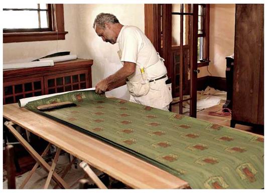
Do the rough-cutting at the table using shears. Do the trimming on the wall using a razor knife. Patterns that run horizontally across the face of a

image963

Use shears to rough-cut strips, leaving extra at each end for trimming and pattern matching. This pasting and layout table is a professional model, strong yet light, easily transported from job to job.


CHAMBER SYSTEMS

Chamber septic systems are used most often when the perk rate on ground is low. Soil with a rapid absorption rate can support a standard, pipe-and-gravel septic system. Clay and other types of soil may not. When bedrock is close to the ground, surface chambers are often used.

Подпись:CHAMBER SYSTEMSПодпись:CHAMBER SYSTEMS
What is a chamber system? A cham­ber system is installed very much like a pipe-and-gravel system, except for the use of chambers. The chambers might be made of concrete or plastic. Concrete chambers are naturally more expensive to install. Plastic chambers are shipped in halves and put together in the field.

Since plastic is a very durable material, and it’s relatively cheap, plastic cham­bers are more popular than concrete chambers.

When a chamber system is called for, there are typically many chambers involved. These chambers are installed in the leach field, between sections of pipe. As effluent is released from a septic tank, it is sent into the chambers. The chambers collect and hold the effluent for a period of time. Gradually, the liquid is released into the leach field and absorbed by the earth. The pri­mary role of the chambers is to retard the distribution rate of the effluent.

Building a chamber system allows you to take advantage of land that would not be buildable with a standard pipe-and-gravel system. Based on this, chamber systems are good. However, when you look at the price tag of a chamber system, you may need a few moments to catch your breath. I’ve seen a number of quotes for these systems that pushed the $12,000 mark. This is more than double what the typical cost for a gravel-and-pipe system in my re­gion. But, if you don’t have any choice, what are you going to do?

Подпись:CHAMBER SYSTEMSA chamber system is simple enough in its design. Liquid leaves a septic tank and enters the first chamber. As more liquid is released from the septic tank, it is transferred into additional chambers that are farther downstream. This process continues with the chambers releasing a pre-determined amount of liq­uid into the soil as time goes on. The process allows more time for bacterial ac­tion to attack raw sewage, and it controls the flow of liquid into the ground.

Подпись: Contractors rarely make their own decisions on how to design or install a septic system. Rely on designs that are drawn by certified professionals. Don’t cut corners to save a few dollars during the installation that could cost you major money when problems arise.If a perforated-pipe system was used in ground where a chamber system is rec­ommended, the result could be a flooded leach field. This might create health risks.

Подпись: FIGURE 14.8 ■ Example of a chamber-type septic field.

It would most likely produce unpleasant odors, and it might even shorten the life of the septic field.

Chambers are installed between sections of pipe within the drain field. The chambers are then covered with soil. The finished system is not visible above ground. All of the action takes place below grade. The only real down­side to a chamber system is the cost.