Installing the Five-by-Ten Rafters
As with the four-by-eight floor joists, we used two different methods of extending the five-by-ten radial roof rafters. The existing rafters, protected by a good overhang, were in excellent condition and extended between 18 and 23 inches (43.7 and 58.4 centimeters) from the cordwood walls. On the east and west rafters (which eventually would have supporting cordwood walls below them), we left the original overhanging rafters as they were, but cut a 2-by-io by 22-inch (5.1-by-
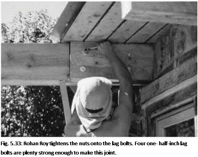
25.4 by 55.9-centimeter) piece out of the new rafters so that they could fit up to the side of the overhanging rafters, as seen in Fig. 5.33. Then we used four one-half – by eight-inch lag bolts to hang the new rafter onto the old. The hex-heads and washers show on the outside. Carriage bolts are an option here.
 Notice, in Fig. 5.33, that the original red pine rafter twisted slightly after construction, as red pine is inclined to do. I was able to straighten the rafter extension by making a biased cut out of the new rafter. This made for a tricky chainsaw cut. The key to success in this sort of thing is to mark the angle correctly on the piece to be cut. And the key to marking it correctly is to double – and triplecheck your angles and measurements. As I tend towards a slight dyslexia on this sort of thing, I would explain what I was doing to willing ears such as Rohan’s. He picks up quickly on wooly-minded thinking.
After the framing was completed, and the roof installed, we covered this rather unattractive join with cordwood masonry. The outside looks great, as if it’s a single rafter originating from the center of the house. On the inside, no rafter is in evidence, as it is hidden behind short log-ends.
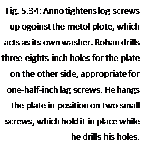
The other three rafter extensions would be exposed in the room, so appearance was important. I designed a rafter plate which could be made from standard one-quarter – by 8-inch (.63- by 20.3-centimeter) steel stock. A twelve – foot section of this material was cut at the local Steel Service Center into six 24- inch (61 centimeter) pieces. I made a hole-drilling pattern out of a piece of plywood, and my friend Bruce Kilgore kindly drilled all the one-half-inch holes for me with his drill press. Before installation, Anna Milburn-Lauer painted all six pieces with two coats of spray-on flat black enamel.
As already stated, truss plates must be used on both sides of the joint for strength. Now, you may be tempted to try to fasten both plates to the rafter by the use of six-inch lag bolts, but leave that temptation behind. The chances of the holes of both plates lining up with holes drilled through the rafter are slim to nil. I saw
an architect-designed detail like this on a job once, where eight-by-eight posts were supposed to be installed into predrilled heavy metal U-shaped post holders, already fastened to the foundation. The architect wanted bolts all the way through, but the contractors couldn’t hit the hole in the plate on the other side, even with their long bits. Lag screws from each side, however, are plenty strong, and that’s what we chose.
![]()


 Each plate would require eight half-inch by з^-іпсії (1.2- by 9.0- centimeter) hex-headed lag screws. Six times eight is 48. It was quite a bit cheaper to buy two boxes with 25 screws per box than to buy 48 pieces out of the bin. So I have two left over.
The new rafter was butted up to the old rafter, with its south end supported by the new girder system, just installed. We jammed a two-by-four under the north end of the new rafter to hold it firmly against the end of the overhanging old rafter. Rohan and Anna installed the plates, as seen in Fig. 5.34.


Leave a reply