UTILITIES/UTILITY EASEMENTS

One of the most prohibitive local residential land development regulations requires placement of all utilities in public rights-of-way. A viable, less costly alternative is installation of utilities outside of the ROW in easements.

Following are guidelines for utilities and utility easements:

• Place utilities in easements instead of rights-of-way where appropriate.

• Use plastic piping in underground gas systems.

• Install direct buried phone, cable TV and electric lines.

• Use common trenching for multiple utility installations.

Подпись: Easements/ Rights-of-Way Utility easements are an acceptable procedure in many areas of the country. Benefits of easements compared to rights-of-way are detailed in the Streets section. Specific to utilities, however, an easement often allows placement of a line in the shortest available path, decreasing the overall length of the line and reducing costs.
UTILITIES/UTILITY EASEMENTS

Home owners maintain and use easement areas, saving the locality money and adding land for the homeowners’ enjoyment. Legal rights to the easement land are assigned to the community, utility companies, and home owners.

Подпись: Materials Several non-traditional materials for use in sanitary sewers, stormwater systems, and water service are discussed in earlier sections. Gas, electric, and cable TV can also use more effective, less costly materials.

Plastic piping, usually polyvinyl chloride (PVC) or polyethylene (PE), is used in underground gas piping systems in lieu of the traditional black or galvanized steel, reducing costs and increasing ease of installation and corrosion resistance.

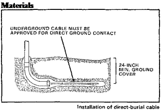
Direct-burial cable can be used for cable TV, phone, and electric lines, eliminating the need for a covering or conduit to serve as a protective sleeve. The National Electric Code (NEC) permits direct-burial cable when a minimum soil cover, or equivalent protection, is provided.

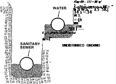
Подпись: InstallationCommon trenching of different combinations of utilities is becoming more acceptable. Common trenching of sanitary sewer and water lines is permitted by the major U. S. model building code organizations – ICBO, BOCA, SBCCI and CABO. Approxi­mately $5 per foot can be saved in installation costs of main lines, with a smaller savings of $2 per foot on service laterals. The water line is generally placed at least 12 inches above the sewer line, with a minimum horizontal separation of 18 inches. However, due to improved reliability in materials and construction techniques,
UTILITIES/UTILITY EASEMENTS

UTILITIES/UTILITY EASEMENTS Подпись: г [ЩіїШг^гг, = i(fsin=w=m-2jifHK(= iu~w-gl

Common water/sewer trench

local codes are beginning to recognize that minimum separation distances are unnecessary.

Common trenching is used successfully with electric, telephone, cable TV, and gas lines. The installation cost is reduced substantially if three or four utility companies share trenching expenses.

The city of Tacoma, Washington, estimates common trenching in residential areas reduces costs, an average of 97 cents per foot where electric, telephone, and cable TV are installed in the same trench. Seattle, Washington, reports savings of 40 percent to 60 percent.

Current Techniques

13.4.1 Lateral Drains

In order to stop water getting into a pavement foundation and to avoid the con­sequent reduction of its support capability, the construction of ditches or trenches is a common procedure. They are usually filled with highly permeable material, wrapped in geotextile and with a perforated tube or porous material near the bottom. Alternatively a geo-composite based drainage system, known as a “fin” drain, may be used. Fin drains are, typically, only a few centimetres thick. Trenches or ditches are, usually, excavated by digging plant while narrow trenches for geo-synthetic fin drains may be dug or may be saw-cut.

These types of systems, named longitudinal drains, are placed in parallel with the road’s centre line, usually at the edge of the pavement structure, and will lie under the surface water channels or gutters whenever these are permeable.

Lateral drains, according to their function, can be divided in two main groups, interceptor drains and water table lowering drains.

Water table lowering drains allow the lowering of the water level in the pavement structure platform, when close to the pavement’s under-side. They are normally placed at depths varying from 1.2 to 2 m below the pavement surface so as to reach the water table (or to reach the height to which the water table may sometimes rise). Thus they keep the water table low and help to prevent the water from being pulled up to the pavement layers by capillarity.

Interceptor drains are drains of the same type as the previous ones, although they usually go down less far into the ground. They aim to ensure the internal drainage of the pavement and to intercept percolating water.

REQUIREMENTS FOR CONSTITUENT MATERIALS

Only constituents with an established suitability are allowed to be used for SMA mixtures. The established suitability means meeting the material requirements of the following:

• A European standard

• A European technical approval (ETA)

• A documented, positive experience with a specific kind of material in the past in which the reference documents confirm the suitability of the material (e. g., test results combined with observations in places of performance)

14.4.1 Binders

Road (paving grade) binder according to EN 12591 and polymer modified binder according to EN 14023 have been used in SMAs. SMA mixtures containing chemi­cally modified binders, which are not classified by the standard EN 14023, are not covered by the clauses of the standard EN 13108-5. Natural asphalts according to EN 13108-4:2005, Annex B, may be added.

14.4.1.1 Road Binder

Road binders after EN 12591 are categorized on the basis of penetration at 25°C and have been incorporated in SMAs. When using them, a binder from the series 30/45 to 330/430 should be selected. This is a very wide range of bitumens (from hard to very soft ones) intended to allow for a wide variety of possible applications depend­ing on local conditions (e. g., climate, traffic loads). In reality, it is for the most part a choice between 50/70 and 70/100.

The Ideal Heating for Room Climate and Health

Because humans do not have the ability to with­stand the natural elements, we wear clothes and build shelters. In cold climates we heat those shel­ters. Many systems have been invented for heating the home, but not all systems are created equal. After examining the criteria that create health and a comfortable indoor climate, I chose to focus my career on the creation of Kachelofens, or masonry oven heating systems, because of their superior quality and performance. A Kachelofen-Masonry Heater is an individually designed, technically cal­culated, thermal mass wood-fired heating system.

From a Building Biology point of view, let us ex­amine the criteria for creating a comfortable and healthy indoor environment and discover why the Masonry Heater is one of the best heating systems for meeting these criteria.

1. Type of Heat: A heating system should create radiant heat, like the heat from the sun. With a radiant heat source, the room air tempera­ture can stay relatively low at 18 to 20 degrees Celsius (64 to 68 degrees Fahrenheit) and still be comfortably warm because, unlike the con­vection heat from a forced-air source, radiant

heat warms walls, floors, and ceilings as well as furniture and bodies and not the room air. Therefore the room air is barely moving, or moving only at low speed, which means no electrostatic charge, no dust circulation, and no transfer of odors. Kachelofens-Masonry Heaters release about 60 to 70 percent radiant heat and only about 30 to 40 percent convec­tion heat, an output not attainable with any other heating system.

2. Temperature: The quality of a heating system should not be measured by high room-air temperatures but rather by low differences be­tween the room-air temperature and the tem­peratures of the walls, ceilings, and floors, as shown in the sketches.

The Ideal Heating for Room Climate and Health

Kachelofen-Masonry Heater

Подпись: Electric Baseboard
Подпись: Iron Wood stove
Подпись: feels most vital when it has the same ion balance as is found in nature. Ideally this would be approximately five positive ions to four negative ions, but homes heated by forced- air or hot appliances create a predominance of positive ions. Dust circulation and electric
Подпись: 3. Heater surface temperature: A heater that has a high surface temperature, such as a radiator or woodstove, causes dust circulation, combustion of dust, and electric discharge of the room air. Electric discharge leads to "dead" air, or a predominance of positive ions. Air

vacuums should have true HEPA filtra­tion or be exhausted to the outside. No chemicals shall be used in the process.

• Prior to occupancy, the air distribution system shall be tested for leakage by a qualified third party or in the presence of the owner or architect. Any leakage greater than 3 percent shall be remedied by the contractor at no additional expense to the owner.

Once the ducts are in place, a regular main­tenance program is essential to maintaining a healthy system. Identify a professional main­tenance company that uses high-powered duct cleaning equipment. Avoid the use of chemical cleaners.

Masonry Ovens

From a Building Biology perspective, the ideal heating system would have the following fea­tures:

• It would be a radiant source.

• It would not rob the air of negative ions. (When air is forced through metal duct­work, negative ions will be attracted to the ductwork and room air ions will be de­pleted.)

• The appliance would not be hot enough to fry dust.

• It would not create “temperature monot­ony” (having all rooms the same temper­ature, which Building Biology considers unhealthy) or drafts.

discharge are major irritants to mucous mem­branes and cause many chronic illnesses and allergies. Since the surface temperatures of Kachelofens-Masonry Heaters are below no degrees Celsius, dust circulation, combustion of dust, and electric discharge of the room air do not occur.

4. Humidity: Room air should have a relative humidity of approximately 50 to 60 percent, which can be achieved only by radiant heat. Heating systems operating with mainly con­vection heat will bring the relative humidity in a room down to 30 percent. To compensate, some forced-air systems have built-in humid­ifiers, but these can cause condensation and mold buildup in the ductwork.

5. Temperature gradients: Convection heat cre­ates horizontal layers of air in a room, with temperature differences up to 10 degrees Cel­sius from floor to ceiling, resulting in hot heads and cold feet. The temperature differences in rooms with radiant heat from Kachelofens – Masonry Heaters are only 1 to 2 degrees Cel­sius, meaning the room is evenly heated.

6. Electromagnetic fields: Heating systems with mainly convection heat (electric and hot – water baseboard heaters and hot-water radia­tors) create electromagnetic fields that cause electric stress. Permanent electric stress can be the cause of illnesses. Kachelofens-Masonry Heaters do not cause electromagnetic fields or electric stress.

7. Ionization of room air: Wood fire creates a neg­ative ionization of the room air. Why is this important? An ion has either a positive or a negative charge. We have positive and nega­tive ions in our body, but when we run, walk, work, or just generally move we lose negative ions. We are left with positive ions, or a posi­tive charge in our body, and we need to find a source of negative ions to balance our positive charge. Wood fire is one of the best sources to recharge our body with negative ions.

8. Noise:The only noise created by Kachelofens – Masonry Heaters is the cozy crackling of the wood fire.

9. Environmental impact: Of all heating systems, the Kachelofen-Masonry Heater has the low­est overall impact on our environment, from production of the building materials to instal­lation, to the amount of fuel required and pol­lution generated, to disposal after a lifetime of at least 80 years. Unlike a woodstove, which in cold climates must burn wood constantly to heat a home, a masonry oven is fired only for a short duration, fully burning the combus­tion gases and storing heat in its mass walls. It therefore uses far less wood than a woodstove and creates very little pollution in the form of smoke.

A study of Kachelofens-Masonry Heaters con­ducted by the Technical University of Vienna showed the following:

• There would be minimal byproducts of combustion.

Wood heat distributed through a masonry oven can fulfill these criteria. The masonry oven, not to be confused with other types of “fireplaces” or woodburning stoves, is de­signed to burn wood so that the gases are completely combusted. The generated heat circulates through multiple chambers within the oven and is distributed into the ovens mas­sive walls before the relatively clean and cool

Criteria

Ideal

Kachelofen

Room Temperature

18 to 20° C

18 to 20° C

Temperature gradient

1 to 2° C

2 to 4° C

Wall temperature

20 to 22° C

18 to 20° C

Humidity

40 to 60 %

40 to 60 %

Air movement

<0.1 m/s

<0.1 m/s

Dust circulation

no

low

Odors

no

low and pleasant

Ionization

natural

natural

Noise

no/pleasant

no/pleasant

Design

individual

individual

The Baubiologische Institut Rosenheim (Ger­many) graded the various heating systems based on the criteria discussed above and came up with the following results:

Forced air/fuel oil 7 points

Hot water in floor/fuel oil 19 points

Wood-fired iron stove 21 points

Kachelofen-Masonry Heater 66 points

The masonry oven and its health, comfort, and ecological benefits are little known in North Amer­ica, where forced-air heating is the norm. If you are interested in heating your home in this time – tested manner you will need to seek out a mason trained in the art of masonry oven building and in­stallation. To find a certified mason in your vicin­ity you can refer to the member directory of The Masonry Heater Association of North America at mha-net. org.

Ernst Kiesling, an Austrian-educated structural engineer, has had a lifelong attraction to healthy living and green building methods. He has been involved with Kachelofens-Masonry Heaters for 31 years, starting out as a teacherfor the profession at a vocational school in Austria and then going into business building individually designed Kache­lofens-Masonry Heaters. After immigrating to Nova Scotia, Canada, he started Kiesling Construc­tion Ltd. to bring the goodness of the Kachelofen – Masonry Heaterto Canada. He can be contacted at Canadian Kachelofen, ermared@ns. sympatico. ca.

exhaust goes up the chimney. Most countries in northern Europe have developed this type of heating to perfection and masonry ovens are common there. There are many masons in the US trained in the art of masonry oven building. The Masonry Heater Association of North America has an informative website that lists trained and certified heater masons by location.

PREPPING RAW DRYWALL OR PLASTER

Newly installed drywall must be sealed before you hang wallcoverings. Otherwise, the drywall’s paper face will absorb paste, making it impossi­ble to remove the covering at a future date with­out damaging the drywall face. To seal drywall, apply a coat of universal primer-sealer, which is an excellent base coat for papering and painting.

Plaster must be well cured before you apply either wallcovering or paint. Uncured plaster contains alkali that is still warm, causing the paint and paste to bubble. "Hot plaster” has a dull appearance, whereas cured plaster has a slight sheen. Curing time varies, but keeping the house warm will hasten it. Cured plaster can also be coated with universal primer-sealer.

Laying Out the Work

Before ordering materials, walk the room and determine if the walls are plumb and if the wood­work is plumb and level. Also, use a long, straight board or a 4-ft. spirit level to determine if the walls have mounds and dips. Use a pencil to circle irregularities so you can spot them easily later. You can hang almost any wallcovering type or pattern, but if door or window casing is markedly out of plumb, small patterns make plumb prob­lems less noticeable than large, loud patterns.

Mold and Mildew

Mold is a discoloration caused by fungi grow­ing on organic matter such as wood, paper, or paste. Mildew is essentially the same, but usually refers to fungi on paper or cloth. Note: Without sufficient moisture and something to eat, mold (and mildew) can’t grow. Mold can grow on the paper and adhesives in drywall; but, technically, mold can’t grow on plaster because plaster is inorganic. If your plaster walls are moldy, the fungi are growing on grease, soap, dirt, or some other organic film on the plaster.

Anyhow, if your walls or ceilings are moldy, first alleviate the moisture. To determine its source, duct-tape a 1-ft.-sq. piece of aluminum foil to a wall. Leave this up for a week. Upon removal, if there’s moisture on the back of the foil, the source is behind the walls. However, if the foil front is damp, there’s excessive mois­ture in the living space, which you might reduce by installing ventilator fans, for starters.

If the drywall or plaster is in good condition, clean off the mold by sponging on a mild deter­gent solution. (Though widely recommended, diluted bleach isn’t any more effective than a household cleaner.) The sponge should be damp, not wet. Rinse with clean water, and allow the surface to dry thoroughly. Then paint on a universal primer-sealer. If you’ll be wall­papering the room, use a mildew-resistant, kitchen-and-bath adhesive.

If mold or water stains are widespread and the drywall has deteriorated, there may be mold in the walls. Remove a section of drywall to be sure. If the framing is moldy, it may need to be replaced—a big job and one worth discussing with a mold-abatement specialist, especially if family members have asthma or chronic respira­tory problems (for more, see Chapter 14).

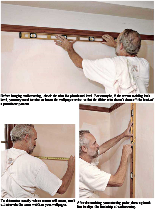
Starting and finishing points. To decide where to hang the first strip, figure out where you want to end. The last strip of wall covering almost always needs to be cut narrower to fit, disrupting the strip’s full-width pattern. Thus avoid hanging the last strip where it will be conspicuous.

A common place to begin is one side of a main doorway. There, you won’t notice a narrow­er strip when you enter the room. And when you leave the room, you’ll usually be looking through the doorway. The last piece is normally a small one placed over the doorway.

Another common starting point is an incon­spicuous corner. To determine exactly where wallcovering seams will occur, mark off intervals the same width as your wallcovering. Go around the room, using a ruler or a wrapped roll of wall­covering as your gauge. Try to avoid trimming and pasting very narrow strips of wallcovering in corners; this usually looks terrible, and the pieces don’t adhere well. You may want to move your starting point an inch or two to avoid that inconvenience.

PREPPING RAW DRYWALL OR PLASTER

Подпись: I Room Focal PointsПодпись:Подпись: PAIRED WINDOWSimage961

PICTURE WINDOW

Centerline

image962

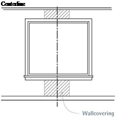
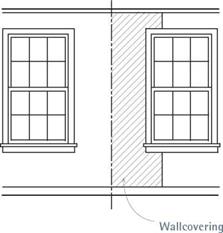
Where windows are the focal point of a room, position the wallcovering accordingly. If the window is a large picture window, center the middle of the strip on the middle of the window. If the focal point is two windows, center the edges of the two strips as shown.

However, if the pattern is conspicuous, you might start layout with a strip centered in a con­spicuous part of a wall—over a mantel, over a sofa, or in the middle of a large wall. Determine such a visual center and mark off roll-widths from each side of the starting strip, until you have determined where the papering will termi­nate, again preferably in an inconspicuous place.

You may want to center the pattern at a win­dow, if that’s indisputably the visual center of the room. In the case of a picture window, the middle of the strip should align with the middle of the window, as shown at left. If there are two windows, the edges of two strips should meet along a centered, plumbed line between the two windows, as shown, unless the distance between the windows is less than the width of a strip. If the distance is less, center a strip between the windows.

Forge bellows and hydraulic energy for metallurgy

According to tradition Tu Shih, the prefect of Nanyang, “loved the common people and wanted to lighten their work”. This is why he decided in 31 AD to use hydraulic ener­gy to power forge bellows, as we have seen earlier. Later in about 238 AD it is once again a man of Nanyang who spreads this technique to other metallurgical centers:

Forge bellows and hydraulic energy for metallurgy

“Han Chi, when Prefect of Lo-Ling, was made Superintendent of Metallurgical Production. The old method was to use horse-power for the blowing-engines, and each picul of refined wrought (iron) took the work of a hundred horses. Man-power was also used, but that too was exceedingly expensive. So Han Chi adapted the furnace bellows to the use of ever-flowing water, and an efficiency three times greater than before was attained. During his seven years of office, (iron) implements became very abundant. Upon receiving his report, the emperor rewarded him and gave him the title of Commander of the Metal-Workers.”[452]

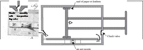
Figure 8.20 The double-action piston bellows: a device to provide a continuous draft for Chinese metallurgy. Above: engraving of Chambers, 1757 (ancient archives of ENPC).

To understand the importance of this invention, whose usage becomes rapidly estab­lished in all of China, one must note how far advanced Chinese metallurgy was com­pared to that of the West.

Melting and casting were practiced in China very early. The key to this metallurgy is the quality of the furnaces and the draft of forced (blast) air that makes it possible to attain elevated temperatures. An illustration dating from 1313 shows the bellows mech­anism powered by hydraulic energy (Figure 8.19). This consists of a horizontal water wheel at the upper end of whose (vertical) axis another horizontal wheel is fixed. Around this latter wheel there passes a belt that drives a third, smaller wheel, which therefore rotates more rapidly. The axis of this small wheel has an eccentric arm on which a cam pivots, thus introducing a rapid alternating movement which in turn activates the bellows.

The bellows itself was initially nothing more than a skin sack fitted with an outlet pipe for the air. Over time, wooden walls are added, and the bellows evolves into an extremely efficient device whose first known description dates from 1280. This was a double-acting bellows, consisting of a piston sliding in a parallelepiped that is divided into two chambers by the piston (Figure 8.20). As the piston moves back and forth, the air in one of the chambers is always being compressed. The evacuated air circulates through a secondary compartment, then into an exit nozzle with a pivoting flap serving as a check valve. Two such check valves also act on each end of the compression cham­bers. The edges of the piston are covered with feathers or paper to limit air leakage. This remarkably simple device delivers a continuous supply of blast air.

Other Considerations

From a pavement point of view, it is desirable to keep the aggregates in the pavement as dry as reasonably possible – so as to promote strength, stiffness and resistance to deterioration (see Chapters 8-10) – but the pervious pavement concept is directly in opposition to the general principle. Therefore other strategies have to be taken to make sure that the pavement provides sufficient strength, stiffness and durability for traffic loading. Normally this requires particular attention to aggregate quality. While, typically, aggregates to a 4-40 mm grading range, or similar, are required to ensure a suitable pore space for water storage, their requirement for durability may be higher than conventionally. There are greater stresses on particles conse­quent on them having an open structure with fewer contact points (see Chapter 9, Section 9.2). Also, more load spreading should be achieved, if possible, in the over­lying pavements. Furthermore the design must allow for softening of the subgrade caused by the water stored in the pavement. Some design information is given in Woods Ballard & Kellagher, (2007) with more information given in Pratt et al (2002) and, for block pavements, Interpave (2005).

STEPS Install the Countertops

Many types of countertops are available these days, but the most common type of affordable countertop is plastic laminate applied over particleboard or MDE Laminate countertops come in many colors and styles. Remember that if you choose this type of countertop, scratches show up more on dark surfaces than on lighter ones. Also, be aware that very hot pans can leave burn marks on laminate countertops. Sometimes, a countertop is also needed in a bathroom, but often the bath vanity comes with a countertop and a sink already attached. A plumber usually installs that type of cabinet.

A countertop ends where it meets a wall or stove and extends 1 in. or so beyond the end of the last cabinet. When I’m ready to install a countertop, I go to a supplier, pick a color, and give the clerk the exact measurements of the base cabinets. I prefer the style of laminate countertop that comes with a backsplash. If you provide the size and location of the sink, the supplier can cut the hole for it, often at no additional cost (see the photo on the facing page). Otherwise, a hole can be cut on the job site with a jigsaw or a reciprocating saw
(sabersaw) equipped with a fine-tooth blade. Just follow the directions that come with the sink. Put some duct tape on the base of the saw to keep it from scratching the laminate surface.

In many Habitat houses, the kitchen layout provides for straight countertop surfaces rather than L-shaped countertops, which are more difficult to install. If you need an L-shaped countertop, the supplier will make the necessary miter cuts and provide special hardware for joining countertop sections from underneath. Before joining mitered sections, put waterproof silicone caulk on the two mat­ing edges.

Test-fit each countertop section, placing it on top of the base cabinets and seeing whether the unit fits properly. If the back – splash doesn’t fit tightly against the wall, fill small gaps with silicone caulk after attaching the countertop. If necessary, especially on a crooked or wavy wall, scribe a line on the backsplash and then use a belt sander to remove material from the backsplash to make it fit against the wall.

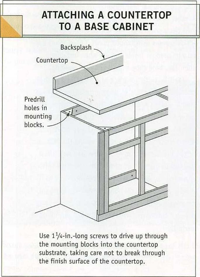
ATTACH THE COUNTERTOP WITH SCREWS.

Usually, base cabinets are built so the top can be screwed directly to them. For some cabinet and countertop combinations, though, a sup­plier may advise you to put strips of lx mate­rial on top of the base cabinets so the counter – top nosing won’t prevent cabinet doors and drawers from opening.

Подпись: CHECK THE MANUFACTURER'S PLANS FOR THE SINK CUTOUT. The dimensions and cutting details for this hole should come with the sink you plan to install. If your countertop supplier can't make the cutout, do it yourself with a jigsaw equipped with a fine cutting blade. [Photo ® Larry Haun.] STEPS Install the CountertopsPrefinished countertops must be attached with screws from below. Attach the countertop by driving l%-in.-long screws up through the lx mounting blocks installed by the cabinet manufacturer (see the illustration at right). Predrill a screw hole through the mounting blocks, but be very careful not to drill or drive the screws so deeply that you break through the finish surface. It’s easy to strip a screw

driven in a countertops particleboard or MDF substrate, so don’t try to drive installation screws extra tight. Complete the job by run­ning a neat bead of silicone caulk between the backsplash and the wall.

STEP 6 Install the Baseboard and Chair Rail

The old house I grew up in had full 1×12 base­boards. In our part of the country, they were called mopboards. In those days, people used big mops to clean their floors with soap and water. The baseboard not only covered the
joint between the plaster and the floor but also protected the walls from being banged by the mop.

Today, baseboard trim is made from real or manufactured wood, and there are many styles available. In the last Habitat house we built here on the coast, we used 1×4 base­boards made of preprimed MDF. Once it was installed and painted, it looked great, but it was so solid that you could hardly drive a nail through it by hand.

In other houses, we have used З-in.-wide trim that’s about % in. thick at the bottom and slopes up to a slender top edge. The thin edge

ACOUSTICAL CONCEPTS

Figure 9.1 illustrates the fundamental function of a noise barrier. The noise source is traffic, particularly large truck traffic, which generates noise by the action of tires on pavement, the drive train, the engine, and the exhaust. The receiver or receptor can be defined as the location where land use results in exposure to highway traffic noise for an hour or more per day. It may typically be set at 5 ft (1.5 m) above ground or at window level. Acoustical design includes controlling noise that passes over the wall and is diffracted to the receiver, noise that is transmitted through the wall, and noise that is reflected from the wall.

Noise levels are expressed in dBA, decibels measured with a frequency weighting network corresponding to the A scale on a standard sound-level meter. The ease of attaining increasing levels of attenuation has been estimated as follows:

5 dBA: simple 10 dBA: attainable 15 dBA: very difficult 20 dBA: nearly impossible

Designs for reductions greater than 15 dBA are usually not considered feasible because of unpredictable and uncontrollable atmospheric and terrain surface effects, scattering from trees and buildings, and other unknowns.

Diffracted Noise. The noise that passes over the barrier, which is the most important of the three types of noise, depends on the location and height of the barrier. Attenuation is directly related to the difference between the length of the path from the source to the receiver in the absence of a noise barrier, and the length of the path from the source over the top of the wall to the receiver by diffraction. At a given distance from the roadway, increasing the barrier height increases the attenuation achieved. However, this relation­ship is obviously nonlinear, and as the height of the barrier increases above some reason­able value, the attenuation that can be achieved decreases rapidly. Assuming a barrier height that just breaks the line of sight from the source to the receiver, and assuming that such a barrier provides a 5-dBA attenuation, a rule of thumb is to assume that an attenua­tion of dBA can be achieved with each additional foot of barrier height. But because the relationship is actually nonlinear, this approximation holds for only a limited range. Sometimes it is possible to take advantage of local terrain and locate a noise barrier on a

всі

SOURCE

FIGURE 9.1 Acoustical concept of noise wall. (From Handbook of Steel Drainage and Highway Construction Products, American Iron and Steel Institute, Washington, D. C., 1994, with permission)
stretch of land at a higher elevation. This reduces the required height and cost. Barrier heights are generally in the range of 6 to 25 ft (2 to 7.5 m). They are generally effective in reducing noise for receptors within approximately 200 ft (60 m) of a highway.

Traffic generates sound waves longitudinally as well as laterally. Thus, care must be taken to extend the length of the barrier sufficiently to achieve the desired end result. A rule of thumb states that the noise barrier should extend, in each direction from the boundaries of the receiver, 4 times the distance from the receiver to the noise wall. This length can be reduced by combining the ends of the barrier with other fea­tures, such as natural knolls, or by flaring the wall toward the land use area to form a barrier to the longitudinal sound waves.

Transmitted Noise. The noise that passes through the barrier depends on its surface characteristics and composition (density). Acoustical performance can be determined by testing in accordance with standards of the American Society for Testing and Materials (Test Designation E90). It is important that the wall not contain gaps or holes. Overlapping sections can be used to accommodate access through the wall for maintenance or other personnel when applicable. In such cases, the overlap should be at least 2.5 to 3 times the width of the opening.

Reflected Noise. There is a possibility that noise barrier effectiveness can be reduced by reflected noise, such as where longitudinal walls are located on either side of the roadway. To avoid this situation, it has been recommended that the width between two parallel barriers be at least 10 times the average height of the barrier above the roadway.

IDENTIFICATION OF AN SMA MIXTURE

The standard stipulates that each delivery ticket should furnish at least the following information:

• Name of the manufacturer and mixing plant

• Mix identification code

• Designation of the mixture in the format

SMA D binder

where D is the maximum aggregate size in millimeters and binder is the binder type. For example, SMA 11 50/70 denotes an SMA mixture with a gradation up to D = 11.2 mm, with the road binder 50/70 (according to EN 12591).

Apart from the aforementioned information, a manufacturer should also provide the following: [73]

• Details regarding the compliance of a mixture with requirements concern­ing resistance to fuel and resistance to deicing fluids (if the delivery applies to an airfield)

• Details of additives used