Fin Drains

Fin drains or drainage screens are also longitudinal drains, manufactured from com­posite materials. Their essential make-up is of two geotextile faces that provide a filter function between the surrounding ground and a rigid plastic core that is sandwiched between the geotextile faces – see Fig. 13.16c. The so-called “drainage core” is, typically, formed of a high-density polyethylene, HDPE, structure. Often this feeds into an integral collector at the bottom. The core permits the water to flow in the plane of the geocomposite (compared with most simple geosynthetics

in which only cross-flow can readily take place). These drains are usually placed at the pavement’s edge, allowing the collector of percolating water (Fig. 13.16a & b). Their main purpose is not to lower the groundwater level. The advantage of fin drains is their narrow thickness, allowing the construction of narrow trenches. This is particularly advantageous in improvement works. The disadvantage is that they are less able to carry high volumes of water and, thus, are less suitable where groundwater lowering of permeable soils is to be attempted.

A fin drain is normally supplied in the form of a roll of constant width. Thus, its height in the ground is constant, too. Care must, therefore, be taken that the base of the slot in which the drain is to be placed will fall evenly towards an outlet rather than following the vertical profile of the pavement alongside which it lies (Highways Agency, 2006).

Trench Drains (“French” drains)

A trench drain consists of drain wrapped in geotextile, see Figs. 13.13-13.15. The drain is made of a mineral material such as a rounded or crushed aggregate. Origi­nally either no carrier pipes orun-jointed pottery pipes were employed at the bottom of such drains. Nowadays, several materials are used for this type of pipe, from perforated or porous concrete, to PVC and fibreglass, the last ones with grooves or perforations. The pores, joints, perforations or grooves are designed to allow water collection. Typical diameters vary from 150 to 200 mm, with a longitudinal gradient that satisfies the self-cleaning condition (> 0.25%). Whenever these drains reach

Fig. 13.13 Conventional trench drain

their maximum capacity, a lateral pipe with the adequate discharge capability should be placed underneath the drains to take away water from the trench. The geotextile is employed as a filter which prevents migration of fine soil particles into the drain and its silting-up. The water permeability of the geotextile should allow water to flow freely from the surrounding ground into the drain. The characteristic pore opening size, 090, of the geotextile used for the trench drain is selected to prevent mixing of soil with aggregate (see Section 13.3.9). Procedures for selection are provided by (e. g.) Christopher & Holtz (1985), Joint Departments (1995) or Koerner (2005).

2 Readers may like to identify violations of safe working practice which can be seen in this picture. The inclusion of this photograph does not mean that the authors condone such practice!

The cross-sectional area of drain is determined depending on the amount of water which ought to be carried away and on the grain-size distribution of the mineral material in the drain. Determining the dimensions is usually performed accord­ing to empirical procedures as the materials, climate, groundwater conditions and materials all have a pronounced influence upon the water that is to be conveyed and that can be carried by the drain.

The pavement layers must be shaped so as to ensure that water in them moves towards the drain and the base of the trench must be substantially lower than the layer to be drained:

• to ensure a suitable hydraulic gradient towards the drain which will drive drainage action;

• to aid entry across the geosynthetic liner which may require a small head differ­ence before wetting is achieved and water passage possible; and

• to ensure that here is adequate capacity within the drain to hold exceptional water flow events without a risk of water flowing from the drain into the layer.

Thus a distance from the base of carrier pipe to the bottom of the layer to be drained of about 0.5 m is typical. Successfully designed and properly made, trench drains have a lot of advantages. Among other things there are (Uzdalewicz, 2001):

• a lengthy life in which it works effectively;

• low construction and operating costs;

• the possibility of managing the “area above the drain”, for example as a footway. The following are the stages of construction of a trench drain:

i) digging of a narrow trench excavation;

ii) cleaning out the narrow trench;

iii) lining of excavation surfaces with geotextile (along the excavation or cut set across excavation) (e. g. Fig. 13.14);

iv) placing a covering of aggregate at the bottom;

v) installing the drain pipe, if needed;

vi) filling the drain volume with aggregate;

vii) closing the drain and jointing of geotextile edges (e. g. with “U” shaped clamps) (e. g. Fig. 13.15a &b); and

viii) covering the closed drain surface with 3-5 cm (or more) of top soil or other low permeability cover (except where surface runoff is also to be collected – see Section 13.3.5).

The minimal length of overlap for geotextiles should be at least 30 cm (Edel, 2002). The longitudinal direction of overlaps should be consistent with the direction of water flow through the drain. The aggregate filling the trench drain should be compacted (in layers).

Flooring

Подпись:

In the old days,

building material to be installed and the first to show its age, as it was crushed by footsteps, swollen by moisture, and abraded by dirt. Foot traffic is as heavy and gritty as ever, but today’s crop of engineered flooring and floor finishes is far more durable—and varied.

However, flooring is only the top layer of a sys­tem that usually includes underlayment and sub­flooring, as well as structural members such as joists and girders. If finish floors are to be solid and long lasting, all parts of the flooring system must be sized and spaced correctly for the loads they will carry. Also, although some flooring mate­rials can withstand moisture better than others, all will degrade in time if installed in chronically
damp locations. In other words, correct under­lying problems before installing new flooring.

This chapter begins by introducing some of the more exciting flooring choices. Then it explains how to strip and refinish wood flooring and how to install wood flooring, resilient floor­ing, and carpeting. Tile floors are covered in Chapter 16.

Flooring Choices

These days, choosing flooring is almost as com­plicated as buying a car. The old standbys such as solid wood, tile, and linoleum have been joined by hundreds of ingenious hybrids, from snap – together laminates that mimic wood or tile to

bamboo planks to prefinished maple the color of plums. To make them tougher, floor finishes may include ceramics, aluminum oxides, or titanium.

Basically, you should try to choose flooring that’s right for the room. Some factors to consider:

► Compatibility with the house’s style or historical period

► Ease of installation

► Ease of cleaning and maintenance

► Scratch and water resistance

► Durability

► Comfort underfoot

► Sound absorption

► Anti-allergenic qualities

► "Green" practices for wood flooring, such as sustainable-forest harvesting

► Cost.

WOOD FLOORING

The revolution that produced engineered lumber has also transformed wood flooring. In addition to solid-wood strips and planks, there are lami­nated floorings, some of which can be sanded and refinished several times. There’s also a wide range of prefinished flooring.

Solid-wood flooring is solid wood, top to bottom. The most common type is tongue-and-groove (T&G) strip flooring, typically 3з4 in. thick by 2J4 in. wide, although it’s also available in h-in.-thick strips and widths that range from 1 h in. to 3J4 in. Hardwood plank flooring is most often installed as boards of varying widths (3 in. to 8 in.), random lengths, and 3з8 in. to M in. thickness. Parquet flooring comes in standard 18-in. by 6-in. by 6-in. squares, though some specialty patterns range up to 36-in. squares.

Because red and white oak look good and wear well, they account for roughly 90 percent of hardwood installations. Ash, maple, cherry, and walnut are also handsome and durable, if some­what more expensive than oak. In older homes, softwood strip-flooring is most often fir, and wide-plank floors are usually pine. If you know where to search, you can find virtually any wood—old or new—which is a boon if you’re restoring an older home and want to maintain a certain look. On the Internet, you can find specialty mills, such as Carlisle Restoration Lumber™, that carry recycled wood that’s often rare or extinct, such as chestnut salvaged from barns or pecky cypress pulled from lake beds. There’s also new lumber made to look old, such as the hand-scraped cherry shown in the photo at right.

It’s not surprising that wood flooring is a sen­timental favorite. It’s beautifully figured, warm

Подпись: These HomerWood® hand-scraped planks have a cinnamon cherry finish. Prefinished flooring, such as this, spares you the effort of sanding, the stink of noxious fumes, and a week of waiting for the floors to dry. hued, easy to work, and durable. Disadvantages: Wood scratches, dents, stains, and expands and contracts as temperatures vary. And, when exposed to water for sustained periods, it swells, splits, and eventually rots. Thus wood flooring needs a fair amount of maintenance, especially in high-use areas. In general, solid wood is a poor choice for rooms that tend to be chronically damp or occasionally wet.

image985

Here’s a typical cross section of solid-wood tongue-and-groove strip flooring.

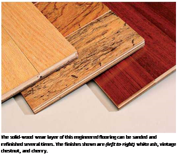
Подпись: The solid-wood wear layer of this engineered flooring can be sanded and refinished several times. The finishes shown are (left to right) white ash, vintage chestnut, and cherry. Подпись: This array of Natural Cork™ flooring is sealed with a UV-cured acrylic finish that keeps out moisture. The cork wear layer is bonded to a high-density fiberboard. Prefinished wood flooring is stained and sealed with at least four coats at the factory, where it’s possible to apply finishes so precisely—to all sides of the wood—that manufacturers routinely offer 15-year to 25-year warranties on select fin­ishes. Finishes are typically polyurethane, acrylic, or resin based, with additives that help flooring resist abrasion, moisture, UV rays, and so on. To its prefinished flooring, Lauzon® says it applies "a polymerized titanium coating [that is] solvent – free, VOC [volatile organic compound] and formaldehyde-free.” Harris Tarkett® coats its wood floors with an aluminum oxide-enhanced urethane. Another big selling point: These floors can be used as soon they’re installed. There’s no need to sand them or wait days for noxious coat­ings to dry.

Tough as prefinished floors are, however, manufacturers have very specific requirements for installing and maintaining them, so read their warranties closely. In many cases, you must use proprietary cleaners or "refreshers” to clean the floors and preserve the finish. Also, board ends cut during installation must be sealed with a fin­ish compatible with that applied at the factory.

Engineered wood flooring is basically an upscale plywood, with a top layer of solid hard­wood laminated to a three – to five-layer plywood base. Most types are prefinished, with tongue – and-groove edges and ends. This flooring is typi­cally sold in boxes containing 20 sq. ft. of 212-in. or 354-in. widths, and assorted lengths.

Engineered wood flooring may be stapled to a plywood subfloor or glued to a concrete slab. Because it’s more dimensionally stable than solid wood, engineered wood is better suited to occa­sionally damp areas such as kitchens or finished basement rooms. And acrylic-impregnated vari­eties are even more moisture resistant.

There are many price points and quality levels of engineered wood flooring, and you get what you pay for. Better-quality flooring has a thicker hardwood layer—Mirage® engineered wood flooring touts its 582-in. hardwood layer on a five – ply board whose total thickness is 58 in. In general, a hardwood layer that is dry sawn will have richer, more varied grain patterns than wood that is rotary peeled or sliced.

Disadvantages: The thin top layer of engi­neered wood flooring can be refinished only a time or two. Mirage maintains that its 532-in. top layer can be sanded three to five times, but that seems optimistic, given the condition of most rental sanding equipment.

TYPES OF NOISE BARRIERS

Except for berms and brick or masonry construction, most noise barriers are of post-and – panel construction, that is, vertical posts spaced a distance apart with horizontal or verti­cal panels running in between. Rails or girts may also run between the posts to support the panels. Posts are embedded in the foundation soil to design depth, which depends on wind loading, soil properties, and frost depth. Brick and masonry walls generally require spread footings, underlain with uniform layers of soil.

According to a 2006 FHWA survey, the main materials that have been used for noise wall construction, in order of usage, are the following:

• Concrete

• Block and brick

• Wood

• Metal

• Earth berms

Other materials sometimes used include plastic, glass, composites, and gabions (rock- filled wire baskets). Glass and clear plastic are alternatives where it is desirable to not block scenic views.

Concrete. Users indicate that selection has been based on cost, durability, low main­tenance, surface treatments available, and acoustical properties. Concrete walls can be precast, cast in place, or of post-and-panel construction. Precast concrete panels may be of either prestressed or reinforced construction. Various surface finishes such as texturing are available and are relatively inexpensive. A 4-in-thick (100 mm) wall pro­vides a relatively high transmission reduction of 32 dBA.

Block and Brick. Brick and masonry construction is also popular, mainly because of its pleasing appearance and acoustical properties. However, initial cost is likely to be higher, depending upon the geographic location, as well as repair cost if damaged. Slump block, cinder block, stone, and brick have all been used. Units can be arranged to produce various patterns. The typical transmission loss is 33 dBA, and this can be improved by the addition of mineral wool or fiberglass to the wall interior.

Wood. Attributes that favor selection include favorable cost, ease of construction, aesthetic appeal, and availability. Disadvantages include shrinkage, warpage, deteriora­tion, difficulty of quality control, discoloration around fasteners, and low resistance to vandalism. Wooden walls have been constructed from timbers, planks, plywood, and laminated products. Often, these materials are used for the panels or facing and con­crete or steel is used for the posts. Tongue-and-groove construction should be used for panels running between posts to eliminate gaps. The durability of wooden walls can be enhanced by using materials that have received a pressure preservative treatment. Wood provides a transmission loss of 18 to 23 dBA/in (0.72 to 0.92 dBA/mm) of thickness.

Metal. Metal walls, primarily of cold-formed steel sheet, can be used as stand-alone barriers or in combination with berms. Low cost, maintainability, and ease of con­struction favor use of steel. Disadvantages include vibration problems, denting, and ineffectiveness in the low-frequency range. For steel construction, the panels are flut­ed (have rectangular corrugations) vertically or horizontally, with a channel-shaped cap at the top. Prepainted galvanized sheet and weathering steel have been used, and other durability treatments are available. The transmission reduction is generally between 10 and 22 dBA.

Earth Berms. Earth berms or mounds are preferred by some. Natural appearance, favorable cost, ready availability of the material, low maintenance cost, and acoustical efficiency favor their selection. A disadvantage is the space needed for construction, particularly in view of safety requirements. Sometimes soil is used in combination with a wall where space is limited. For example, if there is not enough space to achieve the full desired height with a berm, a noise barrier can be located on top of a berm of lower height. Berm side slopes of 4:1 or flatter are desirable on the basis of considerations of safety (see Art. 6.2), roadside maintenance, and wall stability. Some states permit up to 3:1, depending on lateral location. Both acoustics and aesthetics can be improved when the berm is combined with a dense planting of vegetation. Vegetation with a minimum depth of 100 ft (30 m) (perpendicular to roadway), height of 15 ft (4.5 m), and density such that there is no clear path between the highway and the adjacent land use areas can result in a noise level reduction of up to 5 or 6 dBA. Existing soils must be capable of supporting the added berm load.

Proprietary Systems. There are a number of proprietary systems on the market. Some products have included recycled materials such as tire rubber, wood processing waste, and plastics. Of course, steel and aluminum products contain a very high level of recycled metal.

PAPERING AROUND ELECTRICAL OUTLETS AND FIXTURES

О Turn off electricity to the affected outlets and fixtures, and confirm that it’s off by using a voltage tester, as shown on p. 235. Remove the cover plates and other hardware from the outlets so the hardware protrudes as little as possible.

For an outlet relatively flush with the surface, simply position the strip over it. Then, over the center of the outlet, cut a small Xin the strip. Gradually extend the legs of the X until the strip lies flat. Even though the outlet’s cover plate will cover small imperfections in cutting, cut as close as you can to the edges of protruding hardware or the electrical box. Smooth the strip with a smoothing brush, and trim any excess paper. If the edges of the cutout aren’t adhering well, roll them with a seam roller.

It’s preferable to remove fixtures such as wall sconces, but that’s not always possible. For exam­ple, sometimes mounting screws will have rusted so badly that you would damage the fixture trying to remove them. In that case, after matching the wallcovering patterns, cut the strip to the approx­
imate length. Then measure on the wall from the center of the fixture in two directions—say, from the baseboard and from the edge of the nearest strip of wallcovering. Transfer those dimensions to the strip you will hang. If you apply paste after cutting a small X, avoid fraying the edges of the cut with your paste brush or roller.

Hang the strip, and gradually enlarge the X until it fits over the base of the fixture. Smooth down the entire strip, trim closely around the fix­ture, and wipe away any paste that smeared onto the fixture.

PAPERING CEILINGS

In papered rooms, ceilings are usually painted. Even professionals find papering them challeng­ing and time-consuming because you must fight gravity and neck cramps. So get a helper if possi­ble, and paste only one strip at a time until you get the knack of it. Cover ceilings before walls, because it’s easier to conceal discrepancies with wall strips.

Because shorter strips are easier to handle, always hang across the ceiling’s shorter dimen-

Подпись: I Papering an Arch RELIEF CUTS COVERING THE CUTS sion. Snap a line down the middle of the ceiling and work out from it. Cut strips for the ceiling in the same manner described for walls, leaving an inch or two extra at each end for trimming. However, folding the covering is slightly differ­ent. It’s best to use an accordion fold every V/2 ft. or so, which you unfold as you smooth the strips across the ceiling. (Be careful not to crease the folds.)

With your smoothing brush, sweep from the center of the strip outward. Once you have unfolded the entire strip, make final adjustments to match seams, and smooth well. Roll seams after the strips have been in place for about 10 minutes.

ARCHES AND ALCOVES

Papering curved sections isn’t difficult, provided you allow enough extra wallcovering for overlaps and trimming, and for making pattern adjustments.

Before papering an arch, position wall strips so their edges don’t coincide with the vertical (side) edges of the arch. Just as it’s undesirable to have wallpaper seams coincide with an outside corner, seams that line up with an archway cor­ner will wear poorly and look tacky. When hang­ing strips over an arch, let each strip drape over the opening; then use scissors to rough-cut the paper so it overhangs the opening by about 2 in. Make a series of small wedge-shaped relief cuts in the ends of those strips, and fold the remain­ing flaps into the arch. Then cover the flaps with two strips of wallpaper as wide as the arch wall is thick. Typically, these two strips meet at the top of the arch, in a double-cut seam. If possible, match patterns where they meet.

image978Подпись: Overlap the edge of the arch by 2 in. Then cut the overlapping wallcovering with a series of small relief cuts, as shown. Fold the flaps back into the arch and smooth them down. Finally, paper the inside of the arch with two strips that meet in a double-cut seam at the top of the arch, as shown.Double-cutting is also useful around alcoves or window recesses, where it’s often necessary to wrap wall strips into the recessed area. Problem is, when you cut and wrap a wall strip into a recess, you interrupt the pattern on the wall. The best solution is to hang a new strip that slightly overlaps the first, match patterns, and double-cut through both strips. Peel away the waste pieces, smooth out the wallpaper, and roll the seams flat.

image979

I Ceiling Folds


PAPERING AROUND ELECTRICAL OUTLETS AND FIXTURES

An accordion fold is easiest to unfold as you paper a ceiling and helps keep paste off the face of the wallcovering.


image980image981

Risk-based design without flood damage information

Conventional risk-based design and analysis ofhydrosystems requires informa­tion with regard to various flood-related damages. Such information requires an extensive survey of the type and value of various properties, economic and
social activities, and other demographic-related information in the regions that are affected by floods. For areas where flood-related damage data are unavail­able, conventional risk-based analysis cannot be implemented, realizing that in any design or analysis of a hydrosystem one normally has to conduct hy­draulic simulation to delineate the flood-affected zone and other related flow characteristics, such as water depth and flow velocity. The hydraulic charac­teristics, combined with property survey data, would allow estimation of flood damage for a specified flood event under consideration. In the situation where flood-related damage data are unavailable, the risk-based analysis of relative economic merit of different flood defense systems still can be made by replacing the flood-related damage functions with relevant physical performance char­acteristics of the hydrosystems that are either required inputs for hydraulic modeling or can be extracted easily from model outputs. For example, use­ful physical performance characteristics in urban drainage system design and analysis could be pipe length (or street area) subject to surcharge, volume of surcharged water, and maximum (or average) depth and velocity of overland flow. Although these performance characteristics may not completely reflect what the flood damages are, they nevertheless provide a good indication about the potential seriousness of the flooding situation.

For a given design, the corresponding annual installation cost can be es­timated. Also, the system responses under the different hydrologic loadings can be obtained by a proper hydraulic simulation model. Based on the annual project installation cost of the system and the expected hydraulic response of the system, a tradeoff analysis can be performed by examining the marginal improvement in hydraulic responses owing to a one-unit increase in capital investment. Referring to Fig. 8.12 for a study to upgrade the level of protec­tion for an urban drainage system in Hong Kong (Tung and So, 2003), it is observed that the annual expected surcharge volume decreases as the annual capital cost of the system increases owing to increasing level of protection.

Risk-based design without flood damage information

Figure 8.12 Annual project cost versus annual expected surcharge volume. (After Tung and So, 2003.)

The marginal cost MC corresponding to one reduction in surcharge volume can be written as MC = -9C/дSv, with C being the capital cost and Sv being the surcharge volume. As can be seen, the value of MC starts very low for the ex­isting system and increases to an annual capital cost around HK$0.6M (which corresponding to a 10-year protection), beyond which the rate of increase in capital investment per unit reduction in surcharge volume becomes very high. From the trend of marginal cost, a decision maker would be able to choose a sensible level of protection for project implementation.

REQUIREMENTS FOR AN SMA MIX

An SMA formula has to be documented and demonstrated (declared). Any SMA mixture made according to the recipe has to meet the standard requirements deter­mined by a given country.

14.5.1 Gradation

The fundamental rules regarding the mix design include the following:

• The gradation should be expressed in mass percentages of the total aggre­gate mix; the accuracy of percentages passing

• all sieves (with the exception of the 0.063 mm sieve) should be expressed to 1%.

• the 0.063 mm sieve should be expressed to 0.1%.

• The content of binder and additives should be expressed in mass percent­ages of the asphalt mixture, with an accuracy of 0.1%.

• The type of fine aggregate used and the adopted ratios in the case of a mix may be given in a recipe or specification.

• The gradation may be described with either “basic sieve set plus set 1[75]” or “basic sieve set plus set 2t”; a combination of sieves from set 1 to set 2 is not permissible.*

The gradation of an SMA mixture should be established with a minimum of five sieves: 0.063, 2.0, D, 1.4D, and the characteristic coarse sieve (a selected sieve between 2.0 mm and D). Basically, the gradation limits, which are given in the stan­dard, must adhere to the rules for preparing NADs to the standard EN 13108-5. Each country, by its NAD, may determine an SMA mix’s gradation envelopes, guided by the following:

1. Overall limits on the target composition displayed in Tables 1 and 2 of the standard

2. Permissible ranges between maximum and minimum values on selected sieves (in Table 3)

The standard allows for the use of additional control sieves, called optional (char­acteristic) sieves, to enable a more precise description of the gradation as follows:

• A characteristic sieve for fine aggregate may be selected between the

2.0 mm and the 0.063 mm sieves; in addition, the standard stipulates the set of sieves to be chosen from 0.125, 0.25, 0.5, and 1.0 mm;

• An optional characteristic sieve for the coarse aggregate may be selected to provide one more additional sieve with a size between 2.0 mm and D.

Finally, to describe the gradation envelope, one can use the following set of sieves:

• 0.063 mm sieve (obligatory)

• Characteristic sieve for the fine aggregate (optional)—sieve between 0.063 and 2.0 mm,

• 2.0 mm sieve (required)

• Characteristic coarse sieve (required)—a selected sieve between 2.0 mm and D

• Additional characteristic coarse sieve (optional)—a selected sieve between

2.0 mm and D

• Sieve D (required)

• Sieve 1.4D (required)

It is worth noting that the freedom to select characteristic sieves gives a chance to choose those sieves that will provide the best possible control of an SMA mixture (e. g., breakpoint sieves). Figures 14.2 through 14.5 depict the position of boundary points for example mixtures SMA 8 and SMA 11 for sieve set + 1 and SMA 10 and SMA 14 for sieve set + 2. As can be seen, the scope of available solutions (positions of overall limits to a target composition) for any of the mixtures is quite broad. Additionally, in the same figures, the German (for SMA 8 and 11) and British (for SMA 10 and 14) gradation envelopes are presented as examples.

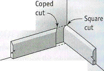
Techniaues CUTTING A COPED JOINT

IF YOU’RE INSTALLING BASEBOARD TRIM that

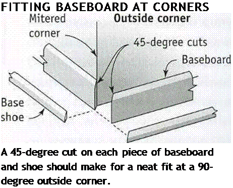
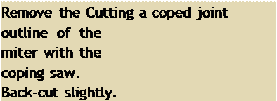
Подпись: FITTING BASEBOARD AT CORNERS A 45-degree cut on each piece of baseboard and shoe should make for a neat fit at a 90-degree outside corner. Подпись: Remove the Cutting a coped joint outline of the miter with the coping saw. Back-cut slightly. Подпись: 45-degreeПодпись: angle Miter /Techniaues CUTTING A COPED JOINTПодпись:Подпись: sawПодпись: Inside cornerПодпись: A coped joint makes a trim fit on an inside corner.Techniaues CUTTING A COPED JOINT

has a rectangular profile, butt one board into another at an inside corner. For baseboard trim that has a shaped profile, it’s customary to make inside corners using coped joints. Coped joints can also be used on inside corners when installing chair rail, base shoe trim, and crown molding.

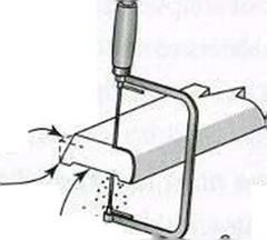
Start by setting a piece of trim upright in the chopsaw and make a 45-degree cut so you can see the face grain of the wood. The long point of the miter cut is toward the back of the material. Then, using a coping saw (or a small jigsaw) fitted with a fine-tooth blade, carefully cut along the outline of the exposed end grain. Tip the saw back a few degrees to give the wood a slight back-cut. This will allow the leading edge of the coped cut to fit tightly against the previously installed baseboard, creating a tight-fitting joint. Use scraps of trim to practice cutting coped joints until you can do them perfectly.

makes it harder for dust to collect on the top. Baseboards still cover the joint between the drywall and the floor and keep the wall from getting banged by a vacuum cleaner. Order long stock from the supplier so you can elimi­nate joints on most walls.

The golden age of the Chinese navy, 9th to the 15th century On the rivers, boats powered by paddle wheels

From the time of the first emperor there was a need for warships in support of military campaigns in the basins of the Yangtze and the Xi (near Canton). These fortified, and sometimes armored, ships were initially powered through oars manned by soldiers. But the specific needs of riverborne military operations led to a very curious invention. It was in 784, under the Tang, that a prince named Li Gao developed warships powered by paddlewheels.[456] This invention may well have come from the 5th century.

This type of boat sees major development on the Yangtze, pushed by a great naval architect named Gao Xuan, at the beginning of the 12th century when the Song retreat into south China. Paddlewheels are mounted on the sides of the vessel; the number of them is variable, but could be as many as eleven on each side, often with a large wheel on the stern in front of the rudder. The wheels are powered by pedalboards, and Chinese authors mention that these ships can attain very high speeds.[457]

The ocean-going junk, precursor of the modern sailboat

We have seen that the technological basis of modern sailboats appeared in China during the Han period, 2nd century AD. The elements of this technology were the axial rudder and the modern sail. Navigation develops widely on the Yangtze, in its immense estu­ary, and along the southeast coasts of China. The marking of the coasts with beacons

develops under the Yuan. Junks having multiple masts appear from the 3rd century.

The large ocean-going junk reaches maturity in the 9th century. This is a very large ship having three or four masts, sometimes even six. In the Song period it can exceed 100 meters in length and can carry several hundred people. One passenger, our Tangiers traveler Ibn Battuta, describes it as follows:

“The large junk has twelve sails, the others (i. e. smaller junks) have up to three. The sails are of bamboo, woven together into mats, they are never lowered but always turn according to the wind direction. When the boat is at anchor, the sails remain hoisted, buffeted by the wind. The crew comprises a thousand men: six hundred sailors and four hundred soldiers: archers, shield carriers, crossbowmen who fire naphtha. [….] On the ship there are four decks with bunks, cabins and salons for the merchants.”[458]

In the 11th century the compass appears on Cantonese junks; before it had been used only by astrologists who assured the correct celestial orientation of dwellings. The com­pass makes seafaring navigation far easier. The large junks navigate on the Sea of China and the Indian Ocean toward Korea, the south of India, and the Persian Gulf. The port of Canton is recognized since the time of the Qin Dynasty; it hosts a cosmopolitan com­munity of sailors and merchants from everywhere. Fuzhou, somewhat further north, is another large port. Hangzhou, a port and city that, in the 13th century, earns the admi­ration of both Marco Polo and Ibn BattUta when they visit, is exceptionally prosperous in the period after the retreat of the Song into south China.

At the beginning of the Ming Empire, grand maritime expeditions are launched on all seas to celebrate the new rulers and the eviction of the detested Mongols. These expe­ditions represent the apogee of navigation in imperial China. Between 1405 and 1433 seven expeditions follow one after another, involving an immense fleet of 62 large junks nearly 130 m long and 50 meters wide, in addition to a number of smaller boats. These expeditions are as much diplomatic as commercial, with destinations of Indochina, Java, Sumatra, the south of India, Ceylon, Hormuz in the Persian Gulf, Jeddah in the Red Sea, Aden and the eastern coast of Africa, and perhaps even Mozambique.[459]

But the decline of seafaring navigation in China begins in the 16th century. This decline results from the quasi state monopoly established by the Ming, who authorize only large official expeditions. This decline coincides also with military setbacks in struggles against the Mongols in the north, and with a pullback of the Ming civilization taking refuge in a sort of defensive posture within the borders of China. Western sailors of the 17th and 18th centuries find the Chinese coasts to be infested with pirates, and witness a population turning its back to its coasts.

Magnetic Fields from Three – and Four-Way Switches

Lights switched from two different locations are called three-way switches. When lights are switched from three or more locations, they

Magnetic Fields from Three - and Four-Way Switches

ground

ndr $ho/Ui


adwg^d (joined^) from Separate ‘circuit


в


deafer

A


^eker c||


trow б^рйгаге cirom’te Kepir е>е£йг<а(ге


nfr


10 ,

greater

0


Magnetic Fields from Three - and Four-Way SwitchesMagnetic Fields from Three - and Four-Way Switches

Magnetic Fields from Three - and Four-Way Switches

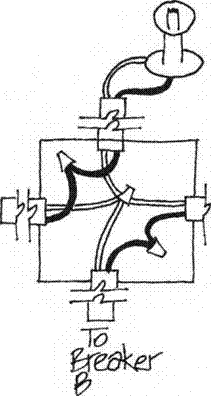
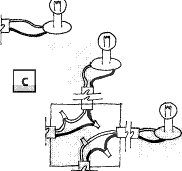
A: 1/2 switched outlet. Both hot and neutral pre-scored conduction tabs must be snapped off when the upper and lower outlets are supplied by separate breakers.

B: Ganging Neutrals. This wiring configuration is wrong and will create net current and magnetic fields.

C:This diagram shows the correct configuration, which will not generate magnetic fields.

Подпись:Подпись: 2 wire RomexMagnetic Fields from Three - and Four-Way Switches2 fomex

1 hot"

I neutral J ground

Properly wired З-way switch.

are called four-way switches. A correctly wired three – or four-way switch will not emit mag­netic fields. However, these switches are often wired incorrectly and thus become a source of magnetic fields that can radiate throughout the room. To avoid improperly wired three – or four-way switches, specify the following:

• Three-wire Romex shall be used between the switches when wiring a three-way switch (see illustration). If alternate wire is used, it shall be twisted.

• Each three – or four-way switch must be controlled by a single breaker.

• All wiring for three – or four-way switches shall be contained in a single run of wire or a single metal conduit. All runs not in a conduit must be bundled.

Fields from Dimmer Switches

Dimmer switches are a source of magnetic and radio frequency fields. If these switches are used, they should be located at a distance from seating and sleeping areas. The most ex­pensive name-brand dimmers tend to emit smaller fields. Choose a model that emits no fields when all the way on or all the way off.