Light-Emitting Diodes Are the Future

LEDs are a Silicon Valley technology, manu­factured in a clean room, just like a comput­er chip. Electrical current runs through the 1-sq.-mm chip, exciting the electrons and creating light. A small bulblike cover focuses the light. LEDs can’t actually produce white light; white light must be created either by combining colors or by using a phosphor coating inside the bulb.

The lighting industry is betting heavily on forging ahead with significant advances in white-light LED technology in the next few years. Many of today’s LEDs, however, already perform well when used in the ap­propriate location.

Подпись:Manufacturers describe LEDs as cool – operating lamps. While it’s true that the lit end of an LED is cool to the touch, the semiconductors do produce heat. And just as computer chips require cooling to perform

Light-Emitting Diodes Are the FutureLight-Emitting Diodes Are the FutureПодпись: Out-of-sight task light. Under cabinets is a natural place to use LEDs because their small size keeps them out of sight and because they're cool to the touch. Also, unlike fluorescents, they don't interfere with radio or TV reception. Lights are available in a range of styles. Select only the amount of light you need so that glare off the counter isn’t an issue. The fixture to the left from Kichler® is one example. Light-Emitting Diodes Are the FutureLight-Emitting Diodes Are the Future

Replacement bulbs. Most LED replacement bulbs are directional for accent or task lights, such as the MR16 replacement from Nexxus, above left. A new generation of LEDs is trying to offer multidirectional ambient light with replacements for fluorescent tubes (from Ilumisys®, above center) and for the common table lamp (from Philips®, above right).

properly, LEDs need thermal management. The heat sink, usually a number of large aluminum fins located near the base of the lamp, is a critical component of an LED.

LEDs are already more efficient than in­candescent bulbs, producing approximately 60 to 70 lumens per watt, and manufactur­ers expect efficiency to surpass that of CFLs soon. Their 50,000-hour average life span translates into 34 years when used four hours a day. There are other advantages to LEDs’ solid-state engineering as well: They are immune to vibration, and their perfor­mance improves in cold temperatures, mak­ing them ideal for outdoor applications.

Cost is currently the biggest drawback to LEDs. A screw-in LED replacement for a

Light-Emitting Diodes Are the FutureLight-Emitting Diodes Are the FutureLight-Emitting Diodes Are the FutureПодпись: Excellent accent lighting. Small disks (from Kichler, above left) and night-lights (from Kichler, above right) provide the low light levels needed for highlighting artwork or providing safe nighttime navigation. Easily concealed, they work in enclosed cabinets without heat buildup and use very little energy to illuminate.recessed light costs about $120, but remem­

ber that LEDs are the lighting equivalent

of a computer chip: Just as Intel® founder Gordon Moore predicted that chip capacity would double every two years (Moore’s Law), Haitz’s Law (named for scientist Roland Haitz) states that every decade, LED prices will fall by a factor of 10 while performance will increase by a factor of 20.

Still, a word of caution is appropriate. There are some well-engineered LED bulbs and fixtures on the market, but with so many manufacturers jumping on the band-

Подпись:Подпись: COMPARING RECESSED FIXTURES Incandescent CFL LED Watts 65 15 12 Lumens 52 675 730 Efficacy (lm/w) 10 45 60

wagon, there are plenty of LEDs with harsh light and poor switching and dimming response. It’s a good idea to evaluate these products carefully before purchasing.

Earthworks Drains

This kind of drainage is installed with the aim of controlling waters emerging from earthworks, which includes not only the water that appears at the base of the exca­vations but also the flow coming from excavated slopes. Five types of systems can be used:

13.4.4.1 Drainage Layers

These consist (see Sections 13.3.4 and 13.3.6) of a layer of granular material with constant thickness (normally between 0.40 and 0.60 m) that is spread at the base of the excavation along the formation, or, for an embankment situation, at its foun­dation (Fig. 13.19). This layer is placed between geotextiles having separation and filter functions.

Fig. 13.19 Drainage layers

At the base of large embankments crossing deep valleys, the main aim may be to keep the water table at its original position in the old valley bottom. For this purpose it may be more desirable to use a series of trenches let into the original valley profile which lead water away before it can rise into the base of the embankment. Due to their appearance in plan these are colloquially known as “Christmas Tree” drainage systems (Fig. 13.20).

Whidbey

The Whidbey’s main floor is simi­lar to that of the B-53 and Enesti, except that it uses a bump-out to house a downstairs bedroom, and it has a full main floor bathroom, in­cluding a sink over the toilet. Pic­tured below is the add-on version with 2 bedrooms. I do not count the upstairs 400+ square feet be­cause, with so much sloped ceil­ing, it does not officially qualify as a habitable room. 1

Square feet: 63

House width: 7’ House length: 10’ Ceiling height: 9’ 6” – sizes are approximate

MOUND SYSTEMS

Mound systems, as you might suspect, are septic systems that are constructed in mounds that rise above the natural topography. This is done to compen­sate for high water tables and soils with slow absorption rates. Due to the amount of fill material to create a mound, the cost is naturally higher than it would be for a bed system.

Подпись: FIGURE 14.9 ■ Cut-away of a mount-type septic system.

Coarse gravel is normally used to build a septic mound. The stone is piled on top of the existing ground. However, topsoil is removed before the stone

is installed. When a mound is built, it contains suitable fill material, an ab­sorption area, a distribution network, a cap, and topsoil. Due to the raised height, a mound system depends on either pumping or siphonic action to work properly. Essentially, effluent is either pumped or siphoned into the dis­tribution network.

As the effluent is passing through the coarse gravel and infiltrating the fill material, treatment of the wastewater occurs. This continues as the liquid passes through the unsaturated zone of the natural soil. The purpose of the cap is to retard frost action, deflect precipitation, and to retain moisture that will stimulate the growth of ground cover.

Подпись: ✓ fast code fact Without adequate ground cover, erosion can be a problem. There are a multitude of choices available as acceptable ground covers. Grass is the most common choice. Mounds should be used only in areas that drain well. The topography can be level or slightly sloping. The amount of slope allowable depends on the perk rate. For example, soil that perks at a rate of one inch every sixty minutes or less, should not have a slope of more than six percent if a mound system is to be installed. If the soil ab­sorbs water from a perk test faster than one inch in one hour, the slope could be increased to twelve percent. These numbers are only examples. A profes­sional who designs a mound system will set the true criteria for slope values. Ideally, about two feet of unsaturated soil should exist between the original soil surface and the seasonally saturated topsoil. There should be three to five feet of depth to the impermeable barrier. An overall range of perk rate could go as high as one inch in two hours, but this, of course, is subject to local ap­proval. Perk tests for this type of system are best when done at a depth of about 20 inches. However, they can be performed at shallow depths of only 12 inches. Again, you must consult and follow local requirements.

RESILIENT FLOORING

Vinyl and linoleum are the two principal resilient materials, available in sheets 6 ft. to 12 ft. wide, or as tiles, typically 13 in. or 12 in. square. Linoleum is the older of the two materials, patented in 1863. It may surprise you to learn that linoleum is made from raw natural materi­als, including linseed oil (oleum lino, in Latin), powdered wood or cork, ground limestone, and resins; it’s backed with jute fiber. (Tiles may have polyester backing.) Because linoleum is comfortable underfoot, water resistant, and durable, it was a favorite in kitchens and baths from the beginning; but it fell into disfavor in the 1960s, when it was supplanted by vinyl floor­ing, which doesn’t need to be waxed.

However, linoleum has proven resilient in more ways than one by bouncing back from near­extinction, thanks to new presealed linoleums that don’t need waxing. In addition, linoleum (sometimes called Marmoleum®, after the longest continuously manufactured brand) has antistatic and antimicrobial qualities. It’s also possible to custom-design linoleum borders and such, which are then precisely cut with a water jet. Flooring suppliers can tell you more.

Vinyl has similar attributes to linoleum, though it is a child of chemistry. Its name is short for polyvinyl chloride (PVC). Vinyl flooring is also resilient, tough to damage, stain resistant, and easy to clean. It comes in many grades, prin­cipally differentiated by the thickness of its top layer—also known as its wear layer. The thicker the wear layer, the more durable the product.

The more economical grades have designs only in the wear layer; whereas inlaiddesigns are as deep as the vinyl is thick. If you’re thinking of installing vinyl yourself, tiles are generally easier, though their many joints can compromise the flooring’s water resistance to a degree.

STONE AND TILE

If stone and tile are properly bonded to a durable substrate, nothing outlasts them. However, hand­made tiles or stones of irregular thickness should usually be installed in a mortar bed to adequately support them. And leveling a mortar bed is best done by a professional. Tile or stone that’s not adequately supported can crack, and its grout joints will break and dislodge. Chapter 16 has the full story.

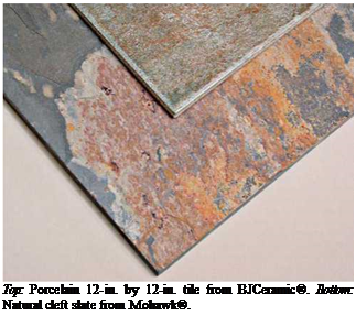
Подпись: Top: Porcelain 12-in. by 12-in. tile from BJCeramic®. Bottom: Natural cleft slate from Mohawk®. Tiles are rated by hardness: Group III and higher are suitable for floors. Slip resistance is also important. In general, unglazed tiles are less

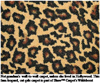
Подпись: Not grandma's wall-to-wall carpet, unless she lived in Hollywood. This faux-leopard, cut-pile carpet is part of Shaw™ Carpet's Wildebeest series. slippery than glazed ones, but all tile and stone— and their joints—must be sealed to resist staining and absorbing water. (Soapstone is the only exception. Leave it unsealed because most stone sealers won’t penetrate soapstone and the few that will make it look as if it had been oiled.)

Tile and stone suppliers can recommend seal­ants, and you’ll find a handful of good ones in "Countertop Choices,” on p. 313. If stone and tile floors are correctly sealed, they’re relatively easy to clean with hot water and a mild household cleaner.

CARPETING

Carpeting is favored in bedrooms, living rooms, and hallways because it’s soft and warm under­foot, and deadens sound. In general, the denser the pile (yarn), the better the carpet quality. Always install carpeting over padding; the denser or heavier the pad, the loftier the carpet will feel and the longer it will last. Wool tends to be the most luxurious and most expensive carpeting, but it’s more likely to stain than synthetics. Good-quality polyester carpeting is plush, stain resistant, and colorfast. Nylon is not quite as plush or as colorfast, though it wears well. Olefin and acrylic are generally not as soft or durable as other synthetics, although some acrylics look deceptively like wool.

Disadvantages: Carpeting can be hard to keep clean, and it harbors dust mites and pet dander, which can be a problem for people with allergies. In general, wall-to-wall carpet is a poor choice for below-grade installations that are not com­pletely dry, because mold will grow on its under­side. Far better to use throw rugs in finished basement rooms.

Electromagnetic Fields: Challenging Unsafe Limits

r

Take on the military, government, electric utili­ties, appliance and cell-phone manufacturers, and the owners of television, radio, and other high fre­quency antennas and you’re in for a major fight. The stakes are huge because since 2003 insurance companies no longer cover eventual (because still unproven) damages caused by electromagnetic fields (EMFs). These are emitted by all from the smallest electrical devices and grounding circuits to high-tension power lines and radar systems.

"Scientists who have persisted in publicly rais­ing the issue of harmful effects of any portion of the electromagnetic spectrum were discredited, and their research grants were taken away," says orthopedic surgeon Robert O. Becker.9 In 2000, the double Nobel prize candidate stated,"I have no doubt in my mind that, at the present time, the greatest polluting element in the Earth’s en­vironment is the proliferation of electromagnetic fields."b

Power utilities and the communications indus­try are especially powerful, says David Carpenter, director of the Institute for Health and the Envi­ronment at the State University of New York (Al­bany). "They have infiltrated the world of science and become the dominant spokespersons to gov­ernment and the public on this issue," he said in a telephone interview. "There’s a huge amount of conflict of interest involved."c

Up to now, industry’s public relations spin doc­tors have delivered. Most lay people, scientists, and journalists still scoff at the idea that EMFs could be dangerous. Butthetide isturning. ln recentyears it seems not a month or season has gone by without another alarming study being published. PR spin is spinning out of control.

Since 1979, more than a dozen epidemiologi­cal studies have associated child leukemia with overexposure to residential magnetic fields. They found that the risk of leukemia doubled when the 24-hour average dose of EMFs measured as low as 1.4 milligauss in young boys. Some studies even found the risk quadrupled above 3 or 4 mil­ligauss. Based on these studies, in 2001 the Inter­national Agency for Research on Cancer (IARC) classified residential — 60 hertz or Extremely Low Frequency (ELF) — magnetic fields as "possibly carcinogenic."d In Quebec, where 73 percent of homes are heated with cheap electricity, one out of five children receives a daily average dose of at least 2 milligauss, according to McGill Univer­sity professor and Hydro-Quebec researcher Jan Erik Deadman. Quebec also has the highest rate of child cancer in Canada (16.5 cases per 100,000 children), according to statistics obtained from the Public Health Agency of Canada. Besides ionizing radiation (X-rays), there are few proven causes of child cancer but many are suspected, including exposure to EMFs, says IARC, which is part of the World Health Organization (WHO).

Pressed by industry lobbyists, WHO has flip – flopped on whether to recommend countries take action to reduce public exposure. In the ab­sence of direct proof of a biological mechanism by which EMFs damage genes, WHO still stands by the 1,000 milligauss daily public exposure limit recommended by the International Commission on Non-Ionizing Radiation Protection (ICNIRP).e But this limit only aims to avoid immediate effects of acute exposure, such as inducing current in the human body. It does not address cancer or other risks from long-term exposure.

Since magnetic fields are generated by the flow of electric current and since global power de­mand is always on the rise, public exposure has multiplied. Electric fields are generated when an appliance is plugged to receive voltage but not necessarily turned on to allow current flow. Few health studies have focused on electric fields. However, in 2007 British scientists discovered that electrically charged particles increase the risk of asthma because they stick to lung and respiratory tract tissue/

In May 2007, the medical journal The Lancet criticized WHO for ignoring important evidence while developing international health guidelines.9 WHO’s EMF research project was also discredited for being 50 percent financed by industry. "Just months after leaving his post as the head of WHO’s EMF project, Mike Repacholi is now in business as an industry consultant," reported Microwave News. b Repacholi denies ever putting industry’s interests above the public’s.

WHO responded by acknowledging that fur­ther EMF research is needed, that "the use of pre­cautionary approaches is warranted" and that "exposure limits should be based on a thorough examination of all the relevant scientific evi­dence." However, it also stated that"assumingthat the association is causal, the number of cases of childhood leukaemia worldwide that might be attributable to [EMF] exposure…represents 0.2 to 4.9 percent of the total annual incidence of leukaemia cases, estimated to be 49,000 world­wide in 2000. Thus, in a global context, the im­pact on public health, if any, would be limited and uncertain."’

This assertion is challenged by experts such as

Carpenter. From 1980 to 1987, he coordinated EMF studies as head of the New York State Power Lines Project. "WHO is grossly underestimating the im­pact," he said in a telephone interview."lt is ignor­ing exposures from appliances, radio frequencies (from wireless appliances and antennas, etc.), as well as other exposures outside of homes, for ex­ample in school. In the mid-1980s, the Savitz study concluded 10-15 percent of all child cancers re­sulted from magnetic field exposure from pow­erlines. Nobody pointed out any errors in Savitz’s logic. It is not unreasonable to say the total contri­bution of EMFs is 20 to 35 percent of child cancers. In my mind, the evidence is overwhelming."

Hundreds of medical studies have also linked various sources of EMFs to numerous ailments and diseases, ranging from depression to skin, eye, heart, reproductive, and neurological prob­lems. That’s why a number of public health experts have mandated or recommended stricter expo­sure guidelines and regulations to protect public health:

• Physicians Suzanne and Pierre Deoux/ French experts in healthy housing, recommend kee­ping these distances from transmission lines: 250 meters from 400 kilovolt lines, 150 meters from 225 kilovolt lines, 100 meters from 63 to 90 kilovolt lines, 40 meters from 20 kilovolt lines, and 5 to 10 meters from transformers. These are conservative by North American standards since magnetic fields are weaker in Europe, where 220-volt tension is used. (Electric fields are thus higher and more worrisome there.)

* In January 2007, the Connecticut Department of Public Health recommended imposing a 10 milligauss limit at the edge of rights-of-way

(land reserved for passing powerlines). Con­necticut Light and Power’s consultants (in­cluding Mike Repacholi) claimioo milligauss is a safe limit.

• In 1996, Sweden recommended that new homes and schools be built at least 75 meters from powerlines and electrical equipment to avoid exposures above 2 milligauss.1

• Since 2000 in Switzerland, new electrical lines and equipment must emit below 10 milligauss in areas where people spend several hours a day. m

• Ontario and Wisconsin politicians have pro­posed legislation requiring that utilities stop using the ground as a return path for over 70 percent of electrical current. Ground currents often harm farm animals as well as humans worldwide."

• Since 1999, several jurisdictions limit the power densities emitted by new or modified base cel­lular telephone antennas. In Switzerland and Toronto, for example, they must be 90 percent lower than the international standard of 1,000 microwatts per square centimeter.0

• In 2007, Carpenter led a group of experts who reviewed 2,000 scientific studies before decla­ring that current EMF public safety limits are inadequate to protect public healths They rec­ommended: a 1 milligauss limit for housing ad­jacent to all new or upgraded power lines and a 2 milligauss limit for all other new construc­tion^ 1 milligauss limit for existing housing to protect children and pregnant women; and a limit of 0.1 microwatt per square centimeter

(also 0.614 volts per meter) for outdoor cumu­lative exposure to radio frequencies.

While outdoor sources are not always the domi­nant source of electropollution, many countries and public utility commissions in California, Colo­rado, Connecticut, and Hawaii have adopted "pru­dent avoidance"q policies. These strike a balance between protecting public health from potential effects of EMFs and implementing reasonable – or modest-cost mitigation measures to lower public exposure. Such efforts send clear signals to buil­ding owners: they too should apply simple and affordable mitigation measures because in most cases the dominant sources of EMFs originate in­doors.

a. Robert 0. Becker. Cross Currents. Tarcher, 1990, page 300.

b. Linda Moulton Howe. British Cell Phone Safety Alert and an Interview with RobertO. Becker, M. D [online]. [Cited November 23,2007.] Council on Wireless Technology Impacts, 2000. energy fields. org/science/becker. html

c. See Albany. edu. ihe.

d. International Agency for Research on Cancer. IARC Finds Limited Evidence that Residential Magnetic Fields Increase Risk of Childhood Leu­kaemia [online]. [Cited November 23, 2007.] Press Release N0.136, June27,2001. iarc. fr/ENG /Press_Releases/archives/pri36a. html

e. International Commission on Non-Ionizing Ra­diation Protection. Guidelines for Limiting Ex­posure to Time-Varying Electric, Magnetic, and

Electromagnetic Fields (Up to 300 GHz) [online]. [Cited December 10, 2007.] icnirp. org/docu ments/emfgdi. pdf

f. K. S Jamieson et al.’The Effects of Electric Fields on Charged Molecules and Particles in Individ­ual Microenvironments." Atmospheric Environ – ment. Vol. 41, no. 25 (April 2007), pp. 5224-5235.

g. Maria Cheng. "WHO Criticized for Neglecting Evidence" [online]. [Cited November 27, 2007.] ABC News, May 7, 2007. abcnews. go. com/ Health/wireStory? id=3i4974o See also An­drew D. Oxman et al."Use of Evidence in WHO Recommendations" [online]. [Cited December

10.2007. ] The Lancet. Vol. 369, no. 9576 (June 2, 2007), pp. 1883-1889. thelancet. com/journals/ lancet/article/PllSoi4o6736o76o6758/abstract

h. "It’s Official: Mike Repacholi is an Industry Con­sultant." Microwave News. Vol. 26, no. 8 (Novem­ber^, 2006), pp. 1-3.

i. World Health Organization. Extremely Low Fre­quency Fields [online]. [Cited December 10, 2007.] Environmental Health Criteria Mono­graph No. 238, 2007. who. int/peh-emf/publica tions/elf_ehc/en/index. html

j. See medieco. info.

k. "Public Health Officials Urge Precaution to Limit Cancer Risk" [online]. [Cited December

10.2007. ] Microwave News. Vol. 27, no. 1, pp. 1-3. microwavenews. com/docs/mwn.1-07.pdf

l. J. M. Danze et al. L’habitat sain? L’electrosmog: le maitriser; le connaitre et s’en proteger. Editions Marco Pietteur, 2002.

m. Swiss Agency for the Environment, Forests and La n d sea pe. Electrosmog in the Environment [on­line]. [Cited December 10,2007.] Swiss Federal Office for the Environment, 2005. bafu. admin. ch/php/modules/shop/files/pdf/phptbAigJ. pdf

n. Electrical Pollution Solutions [online], [Cited No­vember 27,2007.] electricalpollution. com

o. City of Toronto. Reports and Publications: Radiation [online]. [Cited December 10, 2007.] toronto. ca/health/hphe/radiation/radiofre quency. htm

p. David Carpenter and Cindy Sage, eds. Biolnitia – tive Report: A Rationale for a Biologically-Based Public Exposure Standard for Electromagnetic Fields (ELF and RF) [online]. [Cited December 10, 2007.] Bioinitiative Working Group, August 31, 2007. bioinitiative. org/report/docs/report. pdf

q. Leeka I. Kheifets. The Precautionary Principle and EMF [online]. [Cited December 10, 2007.] who. int/pehemf/meetings/southkorea/en/ Leeka_Kheifets_principIe_.pdf

Other excellent sources of information on EMFs are: powerwatch. org. uk/docs/emhealth. asp; next – up. org;and buildingbiology. net (to find an EMF in­spector in the US and Canada).

Andre Fauteux, a journalist by training, has spe­cialized in healthy housing since 1990. A former Montreal Gazette reporter, in 1994 he launched the newsletter La Maison du ne siecle (21st-Century Housing), which in 1997 became Canada’s first green-home magazine. See 21esiecle. qc. ca.

A. Balance-Beam 0 Secondary Rafters

We had the same deck situation upstairs as downstairs: planking span was starting to get rather extreme about six feet from the main building. But, this time, we could use a simple and rather elegant solution not available downstairs: short secondary rafters. They are, I suppose, a kind of double cantilever, but 1 think the term “balance beam” paints a more accurate picture. Have a peek, again, at the rafter plan, Fig. 3.2 on page 109. The four five-foot-long (1.5-meter-long) secondary rafters are supported at their middle by the eight-inch wide girder, with 26 inches (66 centimeters) extending out as overhang, and the other 26 inches extending in as… “underhang?” Whatever you call it, once the planking and heavy roofing is on, these short rafters are perfectly balanced, and their five – by ten-inch dimensions are stout enough to resist the shear and bending stresses of even a very heavy earth roof.

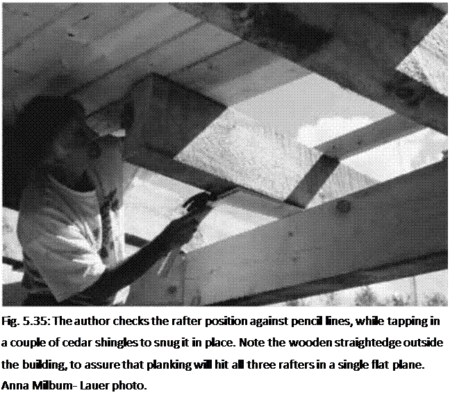
Anna and I installed them in a couple of hours. We’d already prog­ressed with the roof planking beyond the point where the balance beams would go, which helped greatly with their installation. We simply man­handled (and woman-handled) the balance beams up into position, halfway between their longer brothers, and shimmed with shingles until the inner end of the beam was tight against the planking. This can be seen very clearly in Fig. 5.35.

Подпись: Fig. 5.35: The author checks the rafter position against pencil lines, while tapping in a couple of cedar shingles to snug it in place. Note the wooden straightedge outside the building, to assure that planking will hit all three rafters in a single flat plane. Anna Milbum- Lauer photo. When the room was completed,

Jaki “suggested” that I cut a little 45-degree bevel into the rather stark exposed inner right angle of the rafters. I put up a little resistance — circular saw cuts overhead are not my favorite — but her idea is really a great design detail. A picture of this, Fig. 5.44, appears at the end of this chapter.

The Mills of the Middle Ages

The death throes of the aqueducts and the end of the Roman way of life

With the fall of the Roman Empire, the Romano-Hellenistic urban lifestyle in the West begins to retreat rapidly. The roots of this lifestyle are found in the Cretan cities of the Bronze Age. The forums where citizens met to discuss the business of the city are among the victims of the inward-turning that characterized this troubled period. The thermal baths where water so freely flowed disappear; the beautiful public fountains dry up. The cities degrade; new urban streets are unpaved and have neither sewers nor water pipes. Water is no longer delivered, it must be drawn from wells or from the river. This is likely why Lyon, for example, moves down from the heights of Fourviere to the banks of the Saone.

The aqueducts fall into ruin one by one between the 4th and 6th centuries AD, due as much to neglect as to the deliberate action of invaders. And yet these symbols of Roman civilization remain marks of prestige for the powerful ecclesiastics who, one way or anoth­er, manage to restore them sufficiently to supply their palaces in the 8th or 9th century. These personages include Aldric, the bishop of Le Mans; Dieudonne the abbot of Saint- Germain d’Auxerre; Rigobert, the archbishop of Reims; and Didier, the bishop of Cahors. Charlemagne himself has the aqueduct of Aix-la-Chapelle1 restored. In Rome proper, the popes restore several aqueducts to service in the 7th and 8th centuries, to provide water for the mills that they build on the Janicule and for the baptismal fonts of churches.[460] [461] But the people, for their own water needs, must go directly to the Tiber, or dig wells.

It is difficult to determine the number of water mills in use at the end of the Roman Empire. But it is evident that in the 8th and 9th centuries the water mill was widely used in Carolingian agricultural domains in Switzerland and in the northern half of France, whether these domains be lay (the villas) or monastic.[462] The Benedictine abbeys that spring up in this period follow the rule of Saint Benoit which dictates that the monaster­ies be provided with water and a mill:

“(the monastery should be) set up so that everything that is needed can be found there: water,

a mill, a garden and shops so that one can practice diverse trades within the enclosure.”[463]

Where they exist, these water supply systems are nothing more than modest aque­ducts of wood (as at the Swiss monastery of Sant-Gall) or derivations from small rivers (as at the monastery of Fulda in Germany). The importance of these early monasteries to the conservation of hydraulic techniques and the approach to the medieval revival is subject to debate.[464]

In the 9th century, the Viking invaders from the north travel up the rivers and man­age to plunge western Europe into obscurity – it is even forgotten that the earth is round.

With the end of widespread famines and the development of commerce in northern and western Europe, the revival begins in the 10th century, inaugurating a long period of economic and demographic expansion. This expansion will last up until the Hundred Years’ War (1337 – 1453) and the great plague of 1348 – 1349. In the 12th century the monasteries rediscover and reproduce certain ancient authors such as Aristotle and Gallien, from Arab translations brought back from the crusades. These Arab documents are brought from al-Andalus or from Sicily where the Norman kingdom founded in 1061 welcomes Arab and Jewish intellectuals.

The Mills of the Middle Ages

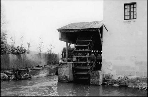
Figure 9.1 The Borde mill at Saint-Jacquest des Guerets, on a race from the Loir, below the medieval site of Troo in the Sarthe department of France (photo by the author)

AESTHETICS

Often, a detailed study is required to address the question of aesthetics. Alternative systems can be compared, with sketches, renderings, plan drawings, and other visual aids prepared to assist in the process. A multidiscipline team approach is desirable, including design engineers, planners, landscape architects, and environmental personnel. Public input to the selection system helps achieve acceptance of the final system. Designers should be concerned with the visual impact from both the driver’s side and the land user’s side of the wall.

Some of the important aspects of aesthetics include scale relationship, relationship to environmental setting, line form, color, and texture. A high barrier alongside a row of single-story houses is not desirable, nor is one placed so close to the residences that unwanted shadows are created. A rule of thumb is to locate the barrier at a distance of atleast 4 times its height from the residences. Barriers higher than 16 ft (5 m) should be critically evaluated for potential unsightly impact.

Evergreens and other plantings are often used with noise barriers to enhance appearance. Vines, encouraged to grow up the posts and across the top, have been appreciated by the public. Most agree that walls with extensive landscaping are the most visually appealing.

When the elevation changes along the length of the wall, it is generally considered more pleasing to step the wall rather than to taper it. Ordinarily, the wall will be con­structed vertically. There has been some use of walls that have the top tilted away from the roadway in an effort to reduce echo, but such walls tend to give the appear­ance of instability when viewed from the back side.

On concrete panel walls, etc., it is necessary to place steel brackets or similar devices at the top of the joints between panels to hold the panels in alignment. A slight horizontal difference of 1 or 2 in (25 or 50 mm) between the tops of adjacent panels may give the illusion that some panels are in distress. This illusion is greatly enhanced by sun shadow lines that, under certain conditions, cast increasing shadows as one looks along the panels. For walls already in place, maintenance forces can tilt panels back in place with a backhoe or similar equipment and add the brackets.

If a barrier is located in an area with dominant architectural features, this should be considered in the selection of barrier material, texture, and color. On the other hand, if located near dominant roadside features such as bridges, there should be an effort to create a strong visual relationship to such features.

In most cases, there should be some consistency in color and surface treatment. For example, some agencies use color scheme and architectural treatment to distinguish between particular corridors.

In general, barriers with darker colors are preferred to lighter ones because they tend to blend better with the background. Although it is usually desirable to avoid visual dominance, murals painted on noise barriers have been well received in some urban regions. The murals tend to discourage graffiti, and in some cases, youth groups have been active in restoring murals defaced by graffiti.

With concrete barriers, a textured appearance can give the effect of shadows and is often considered desirable. Deep textures are more effective than shallow ones. Such treatments can be achieved by a raking technique on the surface of the newly placed concrete. Colors can be obtained with additions to the mix, or by applying a pigmented sealer after the barrier is constructed. The latter technique helps take care of small color variations between panels and minor field problems. Also, coatings can aid in removing graffiti and restoring the intended surface.

For a pleasing visual effect, as well as for safety and acoustic considerations, barriers should not begin or end abruptly. To achieve this, they may be stepped down, flared, or tied into an earth berm, a hillside, a bridge abutment, or another feature. Tapering or stepping is particularly desirable where the height of the barrier exceeds 6 ft (1.8 mm).

Views of several noise walls are shown in Figs. 9.2 through 9.5 to illustrate some of the effects that can be achieved. Figure 9.2 shows concrete-block construction and deep texturing with vertical grooves. The wall is stepped rather than tapered in height. Figure 9.3 shows timber tongue-in-groove construction, with a natural finish and a stepped height. In Fig. 9.4, the alignment of the timber barrier has been changed to a buttress configuration, and extensive plantings have been added. A much different effect has been obtained with concrete post construction, in Fig. 9.5, where the light posts make a distinct contrast with the darker timber.

Making use of variant sun shadow lines on tops of concrete posts yields a changing view of the posts and wall as the sun direction changes during the day. Morning and afternoon shadow lines are greater and thus tend to make aesthetically pleasing wall tops. Also, early morning and late evening sun glare is reduced by north-south noise walls.

FIGURE 9.2 Concrete-block noise barrier with vertical groove treatment, stepped in height.

FIGURE 9.3 Timber noise barrier with tongue-in-groove construction, stepped in height.

FIGURE 9.4 Timber noise barrier with buttress-type alignment.

FIGURE 9.5 Timber noise barrier with concrete posts showing effect of contrasting hues.

Magnetic Fields

The importance of checking the electrical instal­lation under load with a gaussmeter before oc­cupancy is demonstrated in this case study. An electromagneticallysensitiveclient consulted with John by telephone throughout the construction of her home, which was built according to specifi­cations similar to those outlined in this book. After the client moved into her new home, she began experiencing symptoms that occur when she is exposed to elevated magnetic fields, such as ring­ing in the ears and inability to concentrate. Using a gaussmeter, she discovered that about half of the home registered over 5 milligauss. She called John in a state of panic, convinced that her house was ruined and that she would never be able to live in it.

John contacted the client’s electrician and of­fered to help him diagnose the problem over the

telephone. Under John’s guidance, the electrician conducted field testing with the client’s gauss­meter. From the measurements, it became clear to John that the problem was located in the sub­panel controlling a section of the house. At that point, the electrician immediately realized what he had forgotten to do. Some panels and subpan­els are interchangeable except for a single screw that must be removed from the neutral bus bar to electrically isolate it from the ground wires in the panel. Called a bonding screw, it was causing net current in all circuits in the subpanel. The electri­cian simply removed the bonding screw and the magnetic fields dropped in an instant to less than 0.2 milligauss.

detected throughout the structure before it is energized, there is reasonable cause to suspect that fields are entering from an outside source. At this point, consult an expert who can prop­erly block them. Because neighborhood con­ditions may change over time, fields should be checked regularly.

Along with proper bonding and ground­ing, grouping the entry points of all utili­ties will also provide more protection against lightning damage. However, this is not a sub­stitute for lightning rods and lightning surge protection, which are designed to protect the home during a lightning storm.

The following are specifications for pre­venting the entry of magnetic fields through utility services:

• All utilities, including telephone, cable TV, gas, and water, shall enter the build­ing at approximately the same location, within a four-foot radius.

• All utilities entering the structure shall be properly bonded immediately prior to en­try in accordance with the National Elec­trical Code (NEC).

• Bonds or grounds shall occur at only one point along each utility in accordance with the NEC.

• All utilities shall be tested with a gaussme­ter when the house power is turned off. If magnetic fields are detected, inform the owner or architect immediately.