Install the wall cabinets

Wall cabinets are usually installed with their bottom edges 54 in. from the floor, or 18 in. above a countertop (see the illustration on the facing page). Mark a level line for the wall cabinets with a soft pencil, so that it can be erased or easily cov­ered with paint. If there is a kitchen soffit make sure the cabinets are secured to the walls, with their tops fitting snugly against the soffit.

Before hanging wall cabinets, remove the doors and shelves to make the cabinets lighter. Just as with base cabinets, start in a corner and install every unit level and plumb. Use a T-support or something similar to hold a cabinet in place until it is attached to the wall (see the photo at left). Wall cabinets should be set directly above corresponding base cabinets. Drive screws at both the top and the bottom of wall cabinets and into the studs or backing blocks placed in the wall frame.

If there is no backing in the walls, make sure that the screws for the wall cabinets go directly into studs. Kitchen cabinets filled with dishes can be heavy. A friend called me recently and asked me to come by to see whether I could tell her why one of the kitchen cabinets in her new house was sagging. It turns out the installer missed the studs when screwing the cabinet to the wall. To make sure that doesn’t happen, find the location of studs, then transfer those loca­tions to the inside of each cabinet.

IIII III III II III III III II III III III II III III III II III III III II III III II III III III II III III III II III III III II III III III II III III II III III III II III III III II III III III II III III III II III I

Load Combinations

Noise barriers can be designed by working-stress design methods or load factor design. For the working-stress design method, the following load combinations should be considered:

Group I: D + E + SC

Group II: D + W + E + SC

Group III: D + EQD + E

Group IV: D + W + E + I

dead load

lateral earth pressure live load surcharge wind load seismic load ice and snow load

For load combination I, the stresses are limited to 100 percent of the basic allowable stresses. For load combinations II, III, and IV, the stresses are limited to 133 percent.

9.9.2 Design Criteria

The AASHTO Guide Specifications state that, for the design of noise barriers in concrete, timber, or steel, the design should conform to either the AASHTO Bridge Specifications or an industry-recognized design specification. Such sources may be referred to for allowable stress values and other details. For masonry walls, detailed design criteria are presented in the AASHTO Guide Specifications. Other materials can be designed using established engineering principles and appropriate industry specifications.

Electric Fields

Wiring to Reduce Electric Fields

In Germany, Bau-Biologists have long been concerned about the negative health effects associated with exposure to electric fields. In the United States, mainstream science has given little credence to the notion that electric fields pose a health threat and remains skepti­cal in spite of continuing evidence of biologi­cal effects.

A 1996 study by the Ontario Hydroelectric Company indicated a greater than sevenfold increase in cancers among long-term work­ers exposed simultaneously to magnetic and high electric fields.2 The study suggests that the presence of electric fields potentiates the health impact of magnetic fields. Additional data published in 2000 support the role of electric field exposure in leukemia.3 These findings may shed light on why various stud­ies of the impact of magnetic fields alone on humans have been inconclusive.

A proportion of the population appears to suffer from hypersensitivity to electric fields. These individuals may react to exposure with immediate neurological symptoms such as insomnia, depression, and anxiety. One fre­quently reported symptom is that of feeling physically exhausted but too jittery to sleep, or “wired and tired.”

Wiring for reduced electric fields is not required by the electrical code and can be costly. Electric fields generated by wiring can be shielded in metal conduit. This practice is standard in commercial construction but rarely found in residential construction. Even if metal conduit is used, electric fields will still be emitted from appliances or fixtures once they are plugged in unless they have been spe­cially wired or renovated. For people with hy­persensitivity to electric fields, special wiring techniques similar to those used to block elec­trical interference in hospitals and sound stu­dios may be a necessary expense. Techniques for this type of specialty wiring are beyond the scope of this book and will require consulta­tion with an expert.

Wiring for Household Electric Field Reduction

The following instructions may be specified to reduce electric fields generated by household wiring:

• All household wiring shall be placed in MX, MC, or rigid metal conduit.

• All electrical boxes and bushings shall be metal in order to provide shielding of electrical fields throughout the entire run to the panel.

• Avoid running wire behind or under bed placement locations.

Wiring for Electric Field Reduction in the Bedroom with a Kill Switch

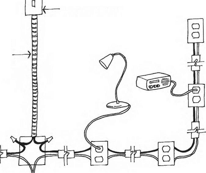
A less expensive approach is to reduce electric fields exclusively in the bedroom by employ­ing a kill switch, which cuts the power to an individual circuit. You can turn off the power to the bedroom just before you retire at night, creating a field-free sanctuary. Because the presence of high electric fields is most com­monly associated with sleep disturbances, we believe that such a device is an important fea­ture in electric field reduction for the healthy bedroom.

Kill switches are most effectively used when wire runs are planned in advance. In brief, certain wiring, such as the wires leading

KTU^I

Подпись:Electric Fieldsoonduih

J -^hoWn

Electric Fields

Electric Fields

Подпись: ^ConWoWed by ^Wifcb |/ ontiate £#nfrfrM .by ^wifcbI

Kill Switch:The kill switch is used to eliminate electric and magnetic fields from plugged in appliances. When the kill switch is off the appliance is off and the fields are eliminated.

to smoke detectors or refrigerators, should not be included with bedroom runs. Typi­cal electrical switches used for freestanding lamps and other electrical appliances turn that equipment off by cutting the power to the hot (black) wire of the equipment. This does not cut off the electrical field as long as the equip­ment is still plugged in. The entire run of wire up to the switch ends up radiating electric fields even when the switch is off. A kill switch is designed to cut off the fields in any given run of wiring. Using a kill switch is especially appropriate for bedrooms, where power isn’t
usually desired or necessary while the occu­pants are asleep.

The least expensive way to accomplish this is to install a double-pole switch in a conve­nient location along the run of electrical wire well before it enters the area of the home to be controlled. Heavy-duty switches have an increased amperage limit rating and can per­form this task as long as the amperage on the circuit beyond the switch does not exceed the amperage limit rating of the switch. Combina­tion electrical outlet and double-pole heavy – duty switch units are available. These contain

Homogeneity and Quality of Coating with Binder

The SMA mixture should be homogenous and completely coated with binder when discharged from the pugmill. There should be no evidence of agglomeration (balling) of the fine aggregate.

14.5.4 Void Content

Void content is one of the essential properties of a compacted SMA mix. Much attention was paid to this subject in the previous chapters, particularly in Chapters 6 and 7. Establishing the method of sample preparation and suitable conditions (compactive effort and compaction temperature) is necessary for the proper deter­mination of air voids in compacted samples. The standard categorizes of minimum and maximum void contents in SMA samples to be selected in an NAD are as follows:

• Minimum void content in SMA samples range from 1.5 to 6% in increments of 0.5% (i. e., Vmin= 1.5, 2. 2.5…)[77] plus VminNR, where VminNR means no requirement.

• Maximum void contents in SMA samples range between 3 and 8% in 0.5% increments (i. e., Vmax= 3, 3.5, 4,.)t plus VmaxNR, where VmaxNR means no requirement.

Pavement Underdrains

In excavated areas and cuttings where the longitudinal slope is more than 3%, a longitudinal water flow may appear fed by water from under the pavement that is

Water*………………. ………………..

table with drain ^ |

separate from the flow in channels, gutters and gully’s. In these cases, the inclusion of pavement underdrains (Fig. 13.26), installed transversally under the pavement, can be used, in order to collect all subsurface waters. These kinds of drain are best constructed in transition areas and, in areas of excavation or fill, placed centrally to improve the rapid flow of the infiltrated water. In sandy soils they should be placed with a spacing between 20 and 25 m while, in very clayey soil, these distances should be reduced to about 5 m.

It is advisable that these transverse drains be constructed in a trench, filled with drainage material wrapped in geotextile, or by synthetic filters, constructed right

down below the level to be drained. In cold regions, the dimensions and depth of the network may be greater than in non-frost affected regions.

STRUCTURAL DESIGN

9.9.1 Noise Barrier Design Loads

Wind Loads. In most cases, the wind load represents the main load. The design pressure depends upon the wind velocity, which should be based upon a 50-year mean recur­rence interval (Fig. 9.6). The wind pressure is applied perpendicular to the wall surface to develop the design wind load. On the basis of AASHTO Guide Specifications for Structural Design of Sound Barriers, the pressure may be calculated from

U. S. Customary units: P = 0.00256(1.3 V)2 Cfc (9.1a)

SI units: P = 0.613(1.3V)2 CdCc (9.1b)

where P = wind pressure, lb/ft2 (N/m2)

V = wind velocity, mi/h (m/s)

Cd = drag coefficient = 1.2 for noise walls

Cc = combined height, exposure, and location coefficient

The factor of 1.3 in Eq. (9.1) provides for wind gusts. Values of Cc and calculated wind pressures are given in Table 9.3 A and B. The following four conditions with increasing levels of wind pressure are included:

1. Noise barriers not located on structures and having exposure B1. This includes urban and suburban areas with numerous closely spaced obstructions having the size of single-family dwellings or larger that prevail in the upwind direction from the noise wall for a distance of at least 1500 ft (457 m).

2. Noise barriers not located on structures and having exposure B2. This includes urban areas with more open terrain that does not meet exposure B1.

3. Noise barriers located on bridge structures, retaining walls, or traffic barriers (exposure C). This is based on open terrain with scattered obstructions.

4. Noise barriers not located on structures and having exposure D. This includes coastal regions.

The interpretation of the surrounding terrain and identification of local conditions that may have increased effect on wind loads are left to the design engineer.

TABLE 9.3A Design Wind Pressures on Noise Walls

Pressure for indicated wind velocity, lb/ft2

Location/

exposure

Height,* ft

Coefficient Cc

70 mi/h

80 mi/h

90 mi/h

100 mi/h

110 mi/h

Ground/Bl

<14

0.37

9

12

16

19

23

14-29

0.50

13

17

21

26

31

>29

0.59

15

20

25

31

37

Ground/B2

<14

0.59

15

20

25

31

37

14-29

0.57

19

25

32

39

37

>29

0.85

22

28

36

44

53

Structuref/C

<14

0.80

20

27

34

42

50

14-29

1.00

25

33

42

52

63

>29

1.10

28

37

46

57

69

Coastal/D

<14

1.20

31

40

50

62

75

14-29

1.37

35

46

58

71

87

>29

1.49

38

50

63

77

94

* Height refers to distance from average level of adjoining ground surface to centroid of loaded area in each height zone.

fStructure refers to noise walls on bridge structures, retaining walls, or traffic barriers.

Source: Adapted from AASHTO Guide Specifications for Structural Design of Sound Barriers, 1989,

and Interim Specifications, 1992 and 2002, Washington, D. C.

Pressure for Indicated wind velocity, N/m2

TABLE 9.3B Design Pressures on Noise Barriers

Location/

exposure

Height,* m

Coefficient Cc

30 m/s

35 m/s

40 m/s

45 m/s

50 m/s

Ground/B1

<4.3

0.37

414

563

736

931

1150

4.3-8.8

0.50

559

761

995

1259

1554

>8.8

0.59

660

898

1174

1485

1834

Ground/B2

<4.3

0.59

660

898

1174

1485

1834

4.3-8.8

0.57

638

868

1134

1435

1772

>8.8

0.85

951

1294

1691

2140

2642

Structuref/C

<4.3

0.80

895

1218

1591

2014

2486

4.3-8.8

1.00

1119

1523

1989

2517

3108

>8.8

1.10

1231

1675

2188

2769

3419

Coastal/D

<4.3

1.20

1343

1827

2387

3021

3729

4.3-8.8

1.37

1533

2086

2725

3449

4258

>8.8

1.49

1667

2269

2964

3751

4631

*Height refers to distance from average level of adjoining ground surface to centroid of loaded area in each height zone.

fStructure refers to noise walls on bridge structures, retaining walls, or traffic barriers.

Source: Adapted from AASHTO Guide Specifications for Structural Design of Sound Barriers, 1989,

and Interim Specifications, 1992 and 2002, Washington, D. C.

Seismic Loads. AASHTO requires that, where structures are designed for seismic load, noise walls also be designed for such. They define the seismic load (EQD) as

EQD = A X f X D (9.2)

where A = acceleration coefficient (varies from 0.05 to 0.40 depending on geographical location; see AASHTO Guide Specifications, Fig. 1-2.1.3)

D = dead load

f = dead load coefficient (2.50, on bridges; 0.75, not on bridges; 8.0, connections of prefabricated walls to bridges; 5.0, connections of prefabricated walls to retaining walls)

The product of A and f must not be taken as less than 0.10.

Other Loads. In addition to dead load, other loads that might be encountered include earth load, live load surcharge, and ice and snow load. When encountered, these loads can be developed from information in the AASHTO Standard Specifications for Highway Bridges. Increased allowable stress levels may be used for certain combinations, as discussed below.

Planking the Roof

We used the same spruce two-by-six tongue-and-groove boards for the roof deck (sunroom ceiling) as we used for the floor. The most difficult part was tearing up a couple of feet of the earth roof on the house, so that we could marry the new roof to the old. I was pleased that the new material — from Russia — was almost identical to the lumber Fd used in the original roof, which was from Quebec. So, once the rafters had been extended, and the old gutter and drip edge removed, Anna and I were able to install the roof deck very quickly indeed, about two days. The work was easier than the floor because 1) we didn’t have to fit the first plank to a cordwood wall, 2) there were only two — large — facets instead of three smaller ones, 3) we were nailing to five-by-eights instead of four-by-tens and 4) we could let all the boards run long and trim the east and west overhangs with one single straight cut. With regard to 4), I let the tongue-and-groove planks overhang eight inches on the east and west walls. More would have been nice, but I was concerned about going too far out with cantilevered planking, considering that the earth roof, soaking wet with snow, can weigh 185 pounds per square foot (903 kilos per square meter).

PROJECT DEVELOPMENT STEPS

Preliminary Engineering. During the preliminary engineering step, the following actions should take place:

• Develop a basic noise abatement plan, and determine barrier height and location.

• Develop alternative methods of abatement such as walls, earth berms, berm-wall combinations, etc.

• Develop alternative locations for abatement facilities.

• Develop alternative material types such as concrete, timber, masonry, or steel.

• Develop a conceptual landscaping plan for each alternative.

• Develop cost estimates for alternatives.

• Develop a general environmental plan.

• Make preliminary arrangements for public informational meetings.

Items to be considered in selecting proposed alternatives include aesthetics, traffic safety, sight distance, drainage, maintenance, existing utilities, lighting, signing, potential soil problems, compatibility with surrounding terrain and land use, and restrictions imposed by available right-of-way. Consider any requirements for snow storage, future construction of sidewalks, trails, etc.

Layouts, cross-sections, and wall profiles should be prepared for each alternative. Aerial photography contour maps should provide sufficient accuracy for determining ground elevations. Supplementary field information may be required in problem areas. Drainage away from both sides of the noise barrier should be provided, with a minimum slope of 0.04. Ditches or culverts may be required where walls or berms alter natural drainage patterns.

Public and Municipal Involvement. Local officials and the affected public should be informed of the scope of the proposed work and the alternative methods being con­sidered to achieve noise abatement. Work through these groups to achieve a consensus. Provide sketches, renderings, plan drawings, and other visual aids to assist in the process. With this input, a public corridor plan should be developed with a consistent theme that considers aesthetics and avoids conflicts with adjacent barriers.

Preparation of Preliminary Plans. Preliminary plans must be prepared for design and safety review. The plans should include a layout with the wall placement and profiles of the ground line and the top of the barrier. Supplemental layouts for sight distance requirements may be required.

Preliminary Approvals. Local approval of the preliminary plan developed is sought at this time. Where applicable, municipal acceptance of maintenance responsibility of back slopes or other areas outside the noise barrier should be obtained. Subsequent approval by the state DOT and FHWA is then sought.

Final Design. Information on soil conditions at the final noise barrier location should be obtained from the soils engineer. The required depth of the investigation should correspond to the depth of post embedment or depth of spread footings. For construction in new embankment areas, care must be taken to avoid excessive differ­ential settlement, because of concern for wall tilting, rotation, or cracking (of rigid systems). If a combination wall and berm is to be constructed, consider specifying an embankment material that will result in an economical wall design. It may be desirable to use a cohesive material of uniform thickness that does not move when saturated with water for the upper portion of the berm.

Wall alignment can be modified slightly when necessary to make adjustments for standard panel sizes or material sizes; to fit with existing features such as trees, signs, lights, or utilities; or to better meet safety or drainage requirements.

Often, wall designs are based on standard agency plans. Special designs may be required where a wall ties into a bridge abutment or retaining wall, where the wall height exceeds the standards, where lights or signs are constructed integrally with the wall, where the wall must also serve as a retaining wall, or where soil properties are outside the range of those anticipated in the design standards.

State and local government agencies sometimes mandate that noise wall corridors be developed. As part of roadway improvement, they anticipate a need by local residents that will help approve the roadway system.

Cut-off Drains

Drains can be placed as a trench or fin at the toe of a cutting, between the cutting and the pavement construction (Fig. 13.23). These act to lower the water in the cutting both increasing the stability of the slope and also reducing the water arriving at, and the pore water pressure in, the foundation of the pavement. Typically these cut-off drains also perform the function of lateral pavement drains (see Section 13.4.1). However, they differ from lateral pavement drains because they are designed to collect water from both sides of the trench or fin.

In porous ground where water tables are high, or high rainfall is anticipated, the drain must be designed to carry relatively large, continuous flows unlike nor­mal lateral pavement sub-surface drains. This may have implications for the design dimensions of the carrier pipe at the bottom of the trench, for the regularity of points at which the trench is emptied to a surface water body or other outlet, and for the accessibility for maintenance. The last point deserves emphasis – if a normally op­erative cut-off drain ceases to function, water pressures will quickly rise in the toe of the cutting slope and in the pavement foundation, leading to rapid pavement dete­rioration and reduced cutting slope stability. In general, fin drains are less desirable when large flows have to be carried away as their capacity is normally less than that of a comparable trench drain.

Longitudinal cut-off drains may also be installed in sidelong earthworks so as to prevent water from ever arriving at the road’s construction. Figures 13.24 and 13.25 give examples.

Binder Content

A series of categories of minimum binder contents in SMA mixes, denoted Bmin, is detailed in the standard. However, maximum binder contents are not defined; therefore an appropriate category of Bmin should be matched with each SMA specification.

The categories given in the standard have been adopted for a reference density of an aggregate mix equal to 2.650 Mg/m3. For aggregate mixtures with other den­sities, the required lower limit of the binder content should be modified using the factor a

2.650 a =

Pa

image164

FIGURE 14.2 The position of boundary points of SMA 11S gradation envelopes according to EN 13108-5 and German final gradation limits for this mixture according to TL Asphalt- StB 07.

Binder Content

FIGURE 14.3 The position of boundary points of SMA 8S gradation envelopes according to EN 13108-5 and German final gradation limits for this mixture according to TL Asphalt – StB 07.


image166

FIGURE 14.4 The position of overall limits to a target composition of SMA 10 accord­ing to EN 13108-5 and British final gradation limits for this mixture according to BS PD 6691:2007.


image165

a

Подпись:Подпись:Подпись: 10 20 30 40 50 60 70 80 90 100 Подпись: CS P4 Подпись: Sieve, # mmimage167a

FIGURE 14.5 The position of overall limits to a target composition of SMA 14 accord­ing to EN 13108-5 and British final gradation limits for this mixture according to BS PD 6691:2007.

where pa is the particle density of the aggregate mix in megagrams per cubic meter, according to EN 1097-6.

The binder content determined for an SMA mixture should be the sum of all pos­sible sources of binder in it, which includes the following:

• Added binder

• Binder from the RAP (when added)

• Natural asphalt (when added)

Available categories of the minimum binder content in SMA (to be chosen in an NAD or a contract specification) range from 5.0 to 7.6% in 0.2% increments (i. e., Bmin= 5.0, 5.2, 5.4, 5.6 …).[76]