Drainage Masks

Drainage masks provide control of emerging water (e. g. a spring line) on a slope’s face with a geotextile covered by hand-placed rock (Fig. 13.21). The material used for a drainage mask should be angular and should comprise 100-500 mm sized stone. The rock provides improved slope stability both by allowing the reduction of pore water pressures without erosion and by adding mass to the slope.

Fig. 13.20 ‘ ‘Christmas tree” drain

Fig. 13.21 Drainage masks

13.4.4.2 Drainage Spurs

Drainage spurs have the double function of draining and reinforcing the excavated slopes. Spurs are constructed as stone-filled trenches excavated perpendicular to the slope face (Fig. 13.22) to provide both drainage and buttress support. The material to be used in drainage spurs should be coarse and angular (e. g. broken rock in the size range 100-200 mm) and should be contained within some geosynthetic wrap to ensure soil does not migrate into the large void space. A heavy-gauge geosynthetic is indicated given the abrasive nature of the fill.

13.4.4.3 Wells

Wells are vertical shafts of sufficient diameter in order to lower the water level. They are usually associated with a pumping system and, hence, require constant maintenance.

MAINTENANCE CONSIDERATIONS

It is wise to keep a stock of compatible replacement materials on hand to repair damage from impact or vandalism. Consideration should be given to keeping replacement materials where they can weather to match installed barriers, such as for pressure-treated timber components. Also, if color is added to concrete panels during manufacture, it is desirable to make future replacement panels in the same operation.

The control of graffiti remains a problem in some urban areas. There are some anti­graffiti surface treatments available, but they are generally costly. Power washing and repainting are current options.

Plantings should be tolerant of roadside environments and require little or no maintenance. Access must be provided to both sides of the barrier for mowing, general maintenance, etc. Sometimes this may require backside access from city streets, or over­lap openings along the length of the barrier. In some cases, arrangements can be made with abutting property owners to maintain the area behind the barrier. If the noise barrier is over 5 ft (1.5 m) high, the right-of-way fence can usually be eliminated.

Some block masonry noise walls and retaining wall combinations made of 2000- to 3000-lb/in[13] [14] [15] [16] [17] [18] [19] [20] (14- to 21-MPa) dry cast units have exhibited extensive disintegration after 3 to 5 years. This disintegration is caused by salt spray from winter driving traffic during removal of snow and ice from the roadways. Testing of blocks removed from barriers showed similar disintegration and chloride ion content on the front and back or fill side. Application of treatments to seal only the front or exposed surfaces will not be effective for the back surfaces. Sealing the surfaces must be repeated and becomes a costly maintenance item. Work is underway to evaluate high – strength (5000-lb/in2) (35 MPa) dry cast blocks that should reduce susceptibility to chloride contaminants.

SAFETY CONSIDERATIONS

Care must be taken not to install a noise barrier in such a way that it will be a safety haz­ard. The general considerations presented in Chap. 6, Safety Systems, apply here. Noise barrier design should incorporate all of the safety design techniques used in the basic roadway design. Examples of features that should be considered include trans­verse location to provide required clear zone, slopes of berms, sight distances, wall ends, plantings, and transitions.

Ideally, noise barriers should be located beyond the clear zone. If not, a traffic barrier may be warranted. It is usually best to design the traffic barrier as part of the noise barrier. If a wall is located at or near the edge of the shoulder, the portion of the wall above the traffic barrier should be capable of withstanding the force of an occa­sional vehicle that may ride up above the top of the barrier. Concrete or masonry construction would often be used in this case. However, laminated wood construction may also be used.

At locations such as ramps, intersections, and merge areas, care must be taken to avoid blocking the line of sight between vehicles. The AASHTO Guide on Evaluation and Abatement of Traffic Noise gives the following suggestions for placement of noise barriers:

For on and off ramps, the minimum set back of a noise barrier is based upon the stopping sight distance, which is a function of the design speed and radius of curvature of the ramp. For ramp intersections, proper barrier location is set by the sight distance corresponding to the time required for a stopped vehicle to execute a left-turn maneuver (approximately 7.5 s). For intersecting roadways, barrier placement is determined from stopping sight distance, which depends on driver reaction time and deceleration rate.

The AASHTO Guide Specifications for Structural Design of Sound Barriers indi­cate that, when locating a sound barrier near a gore area, the wall should begin or end at least 200 ft (60 m) from the theoretical curb nose location.

Protrusions that could constitute a hazard must be avoided near traffic lanes, as well as facings that could become missiles in the event of a crash. Also, surfaces must not create excessive glare.

Sometimes it is necessary to store plowed snow between the roadway and the barriers over a width of 6 to 10 ft (1.8 to 3.0 m). In such cases, it should be removed as soon as practical to avoid blowing on the roadway and freezing. Also, there has been some occasional damage to wall panels from the pressure created by snowplows, and this should be avoided as well. Aside from snow storage, highway engineers should consider the potential for roadway icing problems resulting from deep shadows cast by walls.

The end of a noise barrier or earth berm can be a hazard to approaching traffic. When exposed to approaching traffic within the clear zone area, it should be treated with protection similar to that for other fixed objects. Barrier rails or crash cushions may be appropriate. End slopes for earth berms should be 6:1 or flatter, with 10:1 or 15:1 desirable.

Net Current in Utilities

After purchasing a gaussmeter, an electrician was surprised to discover an elevated magnetic field throughout his entire driveway and a portion of his home. Upon learning that the field did not de­cline when he shut off the power to his home at the main breaker, he concluded that the source of the field was from net current in the gas line. A gas company technician visited the siteand confirmed that the gas line was carrying electricity. There was no cause for concern, he said, because the amount of electricity was small.

The electrician was not comforted by such reassurances. As a specialist in complex wiring

techniques for boats and marinas, he was familiar with the problems of electrolysis and galvanic ac­tion resulting from electricity straying from its in­tended path. He had even witnessed boats at the local marina whose metal had gradually dissolved from exposure to net current. Thus, the electrician reasoned, the net current in his plumbing and gas lines would cause the lines to deteriorate at an ac­celerated rate. After informing the gas company that the galvanic action in the pipes was a liability for the company because of the possibility of an explosion, the electrician was finally able to per­suade the them to take his complaint seriously.

Measuring Magnetic Fields

Magnetic fields are measured with a gaussme­ter. A homeowner might consider purchasing a gaussmeter for one or more of the following reasons:

• to determine safe distances from various household appliances

• to help detect wiring errors that not only produce magnetic fields but also may be fire and electrocution hazards

• as a periodic safety check to determine that no new problems have developed in household appliances

• as a periodic safety check to ensure that no new magnetic fields are entering the home through utility lines

There are two basic types of gaussmeters: single and triple axis. Single-axis meters tend to be less expensive and are slightly more dif­ficult for a novice to use because they must be rotated to align with the flow of the magnetic field in order to detect it. Orienting a triple­axis meter with a field is not necessary because this meter requires positioning only within the range of the field. Less expensive gaussmeters will give false readings when measuring cer­tain magnetic fields such as those generated by computers and electrically ballasted fluo­rescent lights. The following gaussmeters are widely available and are generally adequate for measuring household fields:

• MSI EMF Meter is a single-axis meter that is accurate for field frequencies between 60 and 180 hertz but does not measure higher frequency fields.

• Tri-Field Meter is a low-cost triple-axis meter for measuring magnetic and other fields. The meter may overestimate 60- hertz fields because of interference when higher frequency fields can also be de­tected.

Task and Accent Lighting Require Focused Light

LEDs produce a focused beam of light. Al­though their relatively small output means they can’t throw light as far as some incan – descents, there are plenty of circumstances where they work well as task lights. And they’re ideal for accent lights because they don’t produce UV-light that damages paint­ings and fabrics. Because LEDs are small and easily produced as pucks or strip lighting, they are ideal for undercabinet illumination or as accent lights hidden in coves or inside cabinets, where small size and low heat out­put are important.

Glare can be a concern with bright LED fixtures, especially recessed lights. San Francisco Bay Area lighting designer Eric

Подпись:Task and Accent Lighting Require Focused LightKind of canlike. Although the fixtures look quite common, like the Halo model above, the light module for recessed LED fixtures bears little resemblance to a bulb. With a screw-in adapter like the one shown attached to the Halo module at right, LEDs can be retrofit to existing recessed fixtures.

Подпись: 1 Sources The companies listed here had products that impressed us at LightFair®, the annual lighting-industry trade show. Visit www.americanlightingassoc.com for a comprehensive list of lighting manufacturers. American Fluorescent: Kichler: www.americanfluorescent www.kichler.com .com Lightolier: Cooper Lighting (Halo): www.lightolier.com www.cooperlighting.com MaxLite: Cree: www.maxlite.com www.cree.com Nexxus: Feelux: www.nexxuslighting.com www.feelux.com OSRAM® Sylvania®: Ilumisys: www.sylvania.com www.ilumisys.com Philips: Journee Lighting®: www.journeelighting.com www.philips.com Подпись: Sean Groom is a contributing editor to Fine Homebuilding. He lives outside Hartford, Conn.

Johnson recommends using a diffuser with recessed cans or, at the very least, recessing the bulb as deep into the fixture as possible.

Lightolier®’s Calculite™ is a lensed fixture that uses a diffuser to create white light. Instead of coating the LED bulbs with phos­phor, the phosphor is applied to the diffuser.

Under the first approach, variations in the amount of phosphor coating on each diode affect the overall color of the light. When you have multiple downlights in a room, this can result in variations in the light from the different fixtures. It’s easier to apply an even, consistent phosphor coating to a glass diffuser, improving the consistency and the color of the light. Placing the reflector above the phosphor layer results in more light output than other methods and less glare, according to the manufacturer.

A unique feature of LEDs is that a single fixture with different types of diodes can create multiple temperatures and colors of light, opening new design possibilities for accent lighting.

One last thing: Both CFLs and LEDs can be tricky to dim. The ballasts and drivers, respectively, must be compatible with the dimmers, and the light may cut out before dimming down all the way. This informa­tion is usually indicated on the product.

Подпись: 10

HOW DOES A SEPTIC SYSTEM WORK?

How does a septic system work? A standard septic system works on a very simple principle. Sewage from a home enters the septic tank through the sewer. Where the sewer is connected to the septic tank, there is a baffle on the inside of the tank. This baffle is usually a sanitary tee. The sewer enters the center of the tee and drops down through the bottom of it. The top hub of the tee is left open.

The bottom of the tee is normally fitted with a short piece of pipe. The pipe drops out of the tee and extends into the tank liquids. This pipe should never extend lower than the outlet pipe at the other end of the septic tank. The inlet drop is usually no more than twelve inches long.

The outlet pipe for the tank also has a baffle, normally an elbow fitting. The drop from this baffle is frequently about sixteen inches in length.

When sewage enters a septic tank, the solids sink to the bottom of the tank and the liquids float within the confines of the container. As the tank col­lects waste, several processes begin to take place.

Подпись: been there done that What happens if the drain field doesn’t work? When a septic field fails to do its job, a health hazard exists. This situation demands immediate attention. The main reason for a field to fail in its operation is clogging. If the pipes in a drain field become clogged, they must be excavated and cleaned or replaced. If the field itself clogs, the leach bed must be cleaned or removed and replaced. Neither of these propositions is cheap.

HOW DOES A SEPTIC SYSTEM WORK? HOW DOES A SEPTIC SYSTEM WORK?

SEPTIC TANK MAINTENANCE

Septic tank maintenance is not a time consuming process. Most septic sys­tems require no attention for years at a time. However, when the scum and sludge layers combined have a depth of eighteen inches, the tank should be cleaned out.

Trucks equipped with suction hoses are normally used to clean septic tanks.

The contents removed from septic tanks can be infested with germs. The disease risk of exposure to sludge requires that the sludge be handled carefully and properly.

Refinishing Wood Floors

Wood floor refinishing can be as simple as lightly sanding an existing finish and applying another coat of the same finish or as extensive as strip­ping the floor finish completely and sanding it several times before applying a new finish. If the floor is just grimy and dull from too many coats of wax, it may just need a thorough washing.

If washing doesn’t do the trick, try to determine what the existing finish is before you rent a sander.

THREE TESTS TO DETERMINE A FLOOR FINISH

Wood floors installed in the 1960s or earlier were usually finished with some combination of wax, shellac, and varnish. After that, they were most likely finished with a penetrating oil, or oil – or water-based polyurethane. (For more on finishes,
see p. 494.) Here are a few tests to help figure out what’s there, and what to do next.

Test 1: Wax. Place several drops of water on the floor: If the surface turns white in 10 minutes or 15 minutes, there’s wax on the floor. If the water doesn t leave a white spot, try Test 2. If the finish is dull, try cleaning it with a wax cleaner. If scratches and scuffs are limited, wax will be rea­sonably easy to remove by applying wax stripper or mineral spirits and wiping up the residue. Then apply a new coat of wax. However, if floors are badly abraded and can’t be buffed out, sand the floors, refinish them with a penetrating stain, and then wax them. Even if you sand wax – sealed floors down to bare wood, wax clinging to board edges may prevent a nonwax finish from adhering properly. (Get a second opinion from a professional floor refinisher.)

Test 2: Shellac or varnish. Find an area where the finish is poor shape and scrap it with your thumbnail or a penny. If the finish flakes off, it’s shellac or varnish, which were good in their day but should now be sanded off completely and replaced with polyurethane. If the finish doesn t flake, try Test 3. If the abraded areas are small, try restoring damaged areas by lightly sanding them, vacuuming and dust-mopping them well, then applying a new coat of finish. If there’s not too much sanding to do, you may not need to rent a sander: A random orbital sander with 100-grit or 120-grit sandpaper should do the job. Use a natural-bristle brush or a lamb’s wool pad to apply shellac or varnish.

Подпись: PROTIP If you're not sure what finish was used on floors, first examine old paint and finish cans in the basement, garage, or workshop. The contents of the cans will almost certainly be useless, but their labels may tell you what's on your floors. llll Test 3: Polyurethane. In an inconspicuous place, brush on a small amount of paint stripper. If the finish bubbles, it’s polyurethane. If it doesn’t

image992

Most rental companies offer drum senders because their paper clamping-slots make changing sandpaper easy. Before accepting a rental drum sander, inspect slot lips for nicks or metal spurs, which could damage wood floors. Before leaving the rental company, learn how to insert sandpaper so it’s tight to the drum.


bubble, the floors were probably sealed with a penetrating oil finish. If floor damage is limited, you may be able to touch up the penetrating oil with a similar substance, testing small areas till you find a good color match. If the finish is polyurethane, which is a surface finish, sand the floor lightly if it is in good shape, to help the new coating adhere. Fortunately, polyurethane will stick to other polyurethane even if one is oil based and the other is water based. As long as the base coat is dry, it doesn’t matter whether you apply oil-based urethane over water-based ure­thane or vice-versa. Of course, if the finish is in bad shape, you should sand down the whole floor to bare wood and then re finish it.

RECAP: WHEN TO REMOVE FLOOR FINISHES

Sand floors to bare wood when

Floor finishes are gouged, pitted, or showing bare spots.

Stains go below the surface, such as mold stains beneath potted plants.

► Floorboards are irregular or uneven.

► New finishes won’t adhere to the flooring.

► You need to patch repair rotted or split boards.

► The floor is thick enough to withstand a sanding.


Don’t use chemical paint strip­per to remove a floor finish, even if the floor is painted. Strippers are caustic to wood and haz­ardous to users, and even the smallest residue—between boards, for example—can create adhesion problems for the new finish.


1111


Match the Light to the Job

Both CFLs and LEDs are available with screw-in bases as replacement bulbs for ex­isting fixtures, but if you are building a new home or remodeling, you might consider fixtures dedicated to one technology or the other. Dedicated fixtures can lengthen the lifespan of the bulb and maximize its strengths. Both CFLs and LEDs play a role in providing ambient, accent, task, and deco­rative lighting, the four layers that create a well-lit room. But CFLs and LEDs aren’t necessarily interchangeable. That’s largely because CFLs are a multidirectional light source and LEDs are a point source.

Because they are multidirectional and produce large amounts of diffuse light, CFLs work well for ambient, task, and decorative lighting (photos pp. 160-161). They can be used nearly everywhere that incandescent bulbs are used, particularly in table lamps and in shielded sconces, where the fabric or glass adds color to the light. In the bath­room, when they’re used behind opaque glass, CFLs do a great job of lighting your face. In kitchens, in laundry rooms, and in offices, CFLs produce bright-enough ambi­ent light to illuminate worksurfaces.

CFLs are not appropriate everywhere, however. Locations where lights are switched on and off quickly—say an entry hall or a coat closet—are not ideal because CFLs need time to attain their full brightness and because short-cycle switching reduces the bulbs’ lifespan. Also, if you’re using a CFL bulb in an outdoor fixture, make sure that it’s labeled for outside use, which means that the ballast will work in cold temperatures.


Hold base up г/г in. from floor that will

INSTALLING BASEBOARD ON THE WALLS. ABOVE CARPETED AND VINYL FLOORS


Baseboard

Base shoe


On a vinyl floor, a base shoe can be nailed at the bottom of the baseboard.


Г


Heat register


Where baseboard runs into a heat register, cut the baseboard back 15 degrees on both sides to soften the ends.


INSTALLING BASEBOARD ON THE WALLS. ABOVE CARPETED AND VINYL FLOORSINSTALLING BASEBOARD ON THE WALLS. ABOVE CARPETED AND VINYL FLOORS

The technologies of the medieval revival

The conquest of the waterways: inland water transport and mills

The great technological phenomenon of the Middle Ages is the development of mills, perhaps a natural companion of the revival of interest in watercourses. Since the road network was in bad shape and the countryside was not safe, the development of com­merce in the 10th century first relies on the watercourses. Demographic expansion and the nearly exclusive use of cereals to feed the population drive major development of the flour trade. In this period the consumption of bread made from flour develops while consumption of porridge decreases. It was quite natural to build mills along watercours­es that were already indispensable for water supply and transport, a heritage from the Roman era. The development of mills is nothing less than extraordinary in all the regions of France, England, and Holland. On the Roussillon canal, mills are already numerous at the end of the 9th century, and 10th century mills with multiple wheels can be found on there.[465]

Twenty years after the Battle of Hastings, in 1086, William the Conqueror put together an inventory of the possessions of his English domains in the “Domesday Book”. No less than 5,624 water mills are listed here (but no windmills and only one

The technologies of the medieval revival

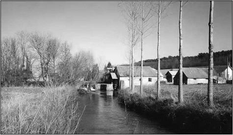
Figure 9.2 A tanning mill (to crush bark for its use in a tannery) on a small river, near Luche- Pringe, in the Sarthe department of France (photo by the author)

tidal mill). This amounts to about one mill for every fifty houses, whereas there had only been a total of about a hundred mills a century earlier. At this period all these mills were for grinding wheat. In other regions, such as Picardy, the use of mills grows rapidly – but one must not take all of the data at face value.[466] Boat-mounted mills can also be found under the Grand Pont of Paris.

In the 10th century mills are for the most part the property of lay lords or bishops. This is the “banal” mill, to which vassals, or feudal subjects, are required to bring their grain to be ground and pay an unpopular tax (the “ban”). But the use of hydraulic ener­gy goes beyond the grinding of cereals. Industrial uses appear very early on as in Andalusia.[467] The fuller’s mill uses a system of cams to beat cloth; it appears in Italy in the 10th century, and in Burgundy (France) in the 12th century. About the same time the use of hydraulic energy to power forgehammers appears using the same principle. The first hydraulic sawmill in the Christian West appears to have been in Normandy (France) in 1204, and further evidence is found here and there in later years. Hydraulic energy has many other such uses: powering bellows for hammer forges, twisting fibers in yarn works, mixing beer, etc.

Horizontal-wheel mills are found in regions under Andalusian influence, for exam­ple along the Garonne River in France. Elsewhere the mills are almost always of verti­cal-wheel design. In the 10th century they are “undershot”, driven from below like the Roman mill described by Vitruvius (Figure 6.21). The overshot wheel is driven from above and can provide more power; it appears in the 11th century in mountain monas­teries, where it is relatively easy to direct falling water to the device.[468]

The cities that begin to develop in the second half of the 11th century in western Europe establish widespread hydrographic networks, branching out from urban centers on the watercourses. Diverse water-dependent activities such as the flour, tanning, and cloth trades[469] develop along these watercourses. Populations are not very dense, and the running water contributes to the healthy environment of these newly emerging cities.

Ownership of the water mills progressively passes to the large abbeys from the 12th century on – the abbeys clearly wanted to take over both the lands and their associated water resources. Further on we describe an example regarding the very rich abbey of Citeaux in Burgundy (Figure 9.11). These ambitions of the abbeys obviously can lead to conflicts, especially when the flatness of the river slope limits the number of mills that can be supported on a given watercourse.

On the Somme river, examination of monastic archives reveals that to the west of Ham there was quite a concentration of mills (Figure 9.4) – no less than eight along some ten kilometers, and most of these mills had more than one wheel. In 1160 the monks of Bonneuil, the important parsonage of Premontre responsible for managing the abbey’s resources in this region, raised the height of the dam of the Eppeville mill (acquired before 1138) to increase its capacity. In so doing, they affected the operation of other mills in Ham, a city located several kilometers further upstream. The trial that followed lasted no less than four years, from 1167 to 1171, and involved jurists as well as lay and religious experts. The case was eventually heard in the court of Pope Alexander III. In the end the monks of Premontre were required to demolish their structure.

We can see that the development of mills necessarily included the transformation of natural rivers into managed watercourses, including overflow weirs to generate the head necessary to power the mills. The mills were sometimes co-located with the dam itself, or sometimes were placed on derivation canals, or races, issuing from the pool upstream of the dam. These races could attain lengths of several kilometers (Figure 9.5). During low-flow periods these installations kept the water level relatively high, thus favoring

The technologies of the medieval revival

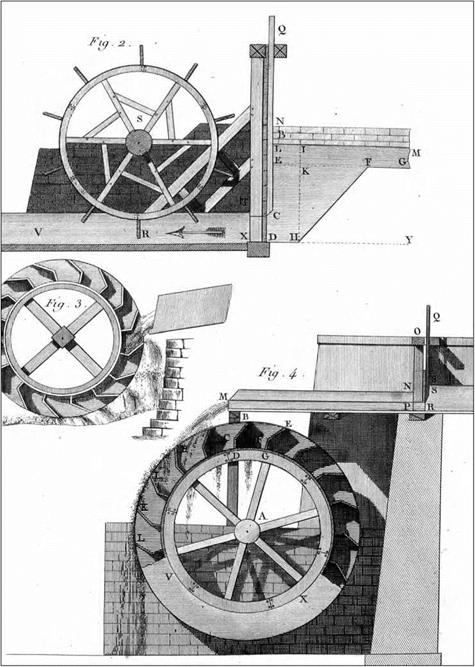
Figure 9.3 Different types of vertical-wheel mills, traditional in France (Belidor, 1737 – ancient archives of ENPC): – above, an undershot wheel, from a river dam (like the mills of Figures 9.1 and 9.2); – below, an overshot wheel, for mountain creeks of low discharge (like the Roman mill of Barbegal, Figures 6.23 and 6.24); – in the middle, an intermediate configuration.

The technologies of the medieval revival

Figure 9.4 The mills on the Somme River (France) west of Ham, in the 12th century. These mills likely existed since the 10th or 11th centuries, and were progressively acquired by the large abbeys like that of Premontre. From Dietrich Lohrmann (1996).

the development of inland water transport.

The earliest navigation canals may have been in the 11th century, but it is not until the 15th century that locks appear in the West. Prior to this, barges had to be hauled up and down ramps. This inconvenience, along with the improvement of the road network, rapidly reduced inland water transport to a rather modest role in the overall interior com­mercial activity in Europe. Ferryboats are put into service for river crossings, and where the overbank area (submerged during floods) is much wider than the main channel (in which year-round navigation is possible), transverse levees must be built on the over­bank to bring the road to the ferry landing and thus make it possible to cross the river in all seasons[470]. Apparently these transverse levees are of little consequence to the flow of water during floods. They cause the upstream water-surface elevation to be higher, but they attenuate the severity of the flood downstream creating a kind of intermediate storage area.

Up until this time mills had only been built on small or modest rivers. But from the start of the 12th century, the know-how for such installations on large rivers began to cross the Pyrenees. At Toulouse a 400-m long dam was built on the Garonne River. This dam was set at an angle to the river to increase the effective overflow length, a technique that we saw earlier on Andalusian dams. The dam was built of two rows of wooden piles anchored in the riverbed, with rock fill dumped between the two rows to form the struc­ture. Along with two other smaller dams, this installation provided the necessary head to power a total of 45 mills, probably a record for this period (the reader may recall the dams built by the Arabs in the Fars, also designed to provide water for a number of mills

The technologies of the medieval revival

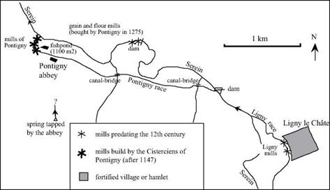
Figure 9.5 Location of mills on the Serein, a tributary of the Yonne, near the abbey of Pontingy in Burgundy (France). The installations at Ligny (dams and race) predate the 12th century. The dam (Figure 9.6), the race and the mills of Pontigny were built after the installation of the Cistercians (1147). Today the three mills of Pontigny have upstream-to-downstream drops of 1.5, 2.6, and 1.3 meters. Numerous conflicts arose between Pontigny and other water users, notably Ligny upstream, and the ancient abbey of Sant-Germain d’Auxerre that had properties downstream on the Serein. From Rouillard (1996) and Kinder 1996).

– Figure 7.4).[471] This dam, whose height is unknown, is mentioned in a text from 1177. To our knowledge, there are no other large structures like this built prior to the 15th cen­tury.