Engineered Lumber

Like any natural product, standard lumber is quirky. It has knots, holes, and splits. And it twists, cups, and shrinks. As mature old-growth timber was replaced by smaller, inferior trees, lumber quality became less reliable—much to the dismay of builders.

In response, the lumber industry combined wood fiber and strong glues to create engineered lumber (EL), including I-joists, engineered beams, plywood, and particleboard. EL spans greater distances and carries heavier loads than standard lumber of comparable dimensions. In addition, EL won’t shrink and remains straight, stable, strong and—above all—predictable.

Still, EL has two main drawbacks: It’s heavy, so dense that it must often be predrilled, and it costs considerably more than sawn lumber. Even so, EL is here to stay.

Подпись: REAL-WORLDПодпись: In an ideal world, every beam is perfectly sized and every purchase is economical. In real life, there's usually a trade-off. Instead of the 2x6 ceiling joists as span charts suggest, a builder may choose 2x10s because they're deep enough to accommodate R-30 attic insulation. Or builders may cut all interior door headers from massive 4x12s because, with 8-ft. stud walls, headers of that depth create the perfect height for standard 6-ft. 8-in. rough openings for doors. And one deep header allows quicker work than if you build headers from 2x lumber and plywood spacers. The same factors apply with engineered lumber: Builders can weigh costs, spans, and loads till the cows come home, but most times they rely on a blend of an engineer's specs, lumberyard recommendations, and their own gut feelings. Подпись: Alternatives to Solid-Wood Joistsimage113"image114

TRUSSES

The most common truss is the prefabricated roof truss, which is a large triangular wood frame­work that serves as the roof’s support structure. Its short web-like reinforcing members are fas­tened by steel truss plates. Trusses are lightweight, cheap, quick to install, and strong relative to the distances they span. Thus they eliminate the need for deep-dimensioned traditional roof rafters and complex cutting.

► Advantages: Trusses can be prefabri­cated for almost any roof contour, trucked to the job site, and erected in a few days. In addi­tion, you can route ducts, pipes, and wiring through openings in the webbing—a great advantage in renovation work.

► Disadvantages: Roof trusses leave little living space or storage space in the attic.

Adding kneewalls on the sides will gain some height, but your design options will be limited. Roof trusses should be engineered and factory built and never modified, unless an engineer approves the changes; otherwise, unbalanced loads could cause the trusses—and the roof— to fail.

Floor trusses, on the other hand, are often open webs spaced 24 in. on center. Although their spanning capacities are roughly the same as I-joists of comparable depth, it’s much easier to run ducts, vents, wiring, and plumbing through open-web trusses.

I-JOISTS

I-joists are commonly called TrusJoists®, after a popular brand (now a subsidiary of Weyerhaeuser®). Typically, I-joists are plywood or OSB (oriented strand board) webs bolstered by stiff lumber flanges top and bottom, which add strength and prevent lateral bending.

Although I-joists look flimsy, they are stronger than solid-lumber joists of comparable dimen­sions. Whereas solid joists are spaced 16 in. on center, I-joists can be laid out on 19h-in. or 24-in. centers. They are also lightweight, straight, and stable. Floors and ceilings constructed with I-joists stay flat because there’s virtually no I-joist shrinkage; hence almost no drywall cracks, nail pops, or floor squeaks.

Installing I-joists is not much different from installing 2x lumber, but blocking between I-joists is critical. (They must be perfectly perpen­dicular to bear loads.) You can drill larger holes in I-joist webs than you can in solid lumber, but religiously follow manufacturer guidance on hole size and placement. And never cut or nail into I-joist flanges.

D Lumber BUYING

Manufacturers continue to develop more eco­nomical I-joist components. Webs may be ply­wood, particleboard, or LVL (laminated veneer lumber). Flanges have been fabricated from LVL, OSB or—back the future!—solid lumber (2x3s or 2x4s) finger-jointed and glued together. I-joists with wider flanges are less likely to flop and fall over during installation. Plus they offer more sur­face to glue and nail subflooring to.

BASIC OFFSETS

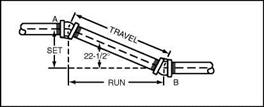
Basic offsets are all based on the use of right triangles. You now know about Set and Travel. It is time that you learned about a term known as Run. Travel, as I said earlier, is the distance between center of two offset fittings that cre­ates the length of a piece of pipe. This pipe’s length is determined as it devel­ops from fitting to fitting, traveling along the angle of the offset. When you want to know the Run, you are interested in the distance measured along a straight line from the bottom horizontal pipe. Refer to Fig. 2.4 for an example

Inches

Decimal of an inch

Vf>4

.015625

Mu

.03125

M«4

.046875

VlS

.0625

Мб4

.078125

Mu

.09375

‘/64

.109375

Ms

.125

%4

.140625

Mu

.15625

"/S4

.171875

M,6

.1875

1 ,5/b4

.203125

Mu

.21875

‘Мб4

.234375

У*

.25

1?/б4

.265625

Мз2

.28125

‘%4

.296875

Mis

.3125

2 Vf»4

.328125

"Mu

.34375

2:!/s4

.359375

Ms

.375

3MS4

.390625

‘М32

.40625

ZMS4

.421875

Ml 6

.4375

29/s4

.453125

‘Mu

.46875

:,1/S4

.484375

‘/2

.5

Inches

Decimal of an inch

3M64

.515625

‘Mu

.53125

3M64

.546875

M.6

.5625

3Ms4

.578125

‘Mu

.59375

3Мб4

.609375

Ms

.625

41/64

.640625

2Mu

.65625

4M«4

.671875

"/is

.6875

4MS4

.703125

2Mu

.71875

4Мб4

.734375

3/4

.75

49/64

.765625

2Mu

.78125

51/64

.796875

‘Ml6

.8125

5M«4

,828125

2Mu

.84375

3Мб4

.859375

Ms

.875

SM«4

.890625

22/32

.90625

59/64

.921875

‘Mi 6

.9375

61/64

.953125

31/32

.96875

6Мб4

.984375

1

1

FIGURE 2.3 ■ Decimal equivalents of fractions of an inch.

BASIC OFFSETS

FIGURE 2.4 ■ Simple offsets.


of what I’m talking about. Run is a term applied to the horizontal measurement from the center of one offset fitting to the center of the other offset fitting.

Most charts and tables assign letters to terms used in formulas. For our purposes, let’s establish our own symbols. We will call the letter S—Set, the letter R-Run, and the letter T—Travel. What are common offsets in the plumbing and pipe fitting trade? A 45° offset is the most common. Two other offsets sometimes use are 60° bends and 22V2° bends. These are the three most frequently used offsets and the ones that we will concentrate our efforts on.

The use of the right triangle is important when dealing with piping off­sets. The combination of Set, Travel, and Run form the triangle. I can provide you with a table that will make calculating offsets easier (Fig. 2.5), but you must still do some of the math yourself, or at least know some of the existing figures. This may seem a bit intimidating, but it is not as bad as you might think. Let me explain.

As a working plumber or pipe fitter, you know where your first pipe is. In our example earlier, where there was ductwork that needed to be cleared, you can easily determine what the measurement of the higher pipe must be. This might be determined by measuring the distance from a floor or ceiling. Either way, you will know the center measurement of your existing pipe and the cen­ter measurement for where you want the offset pipe to comply with. Know­ing these two numbers will give you the Set figure. Remember, Set is meas­ured as the vertical distance between the centers of two pipes. Refer back to Fig. 2.1 if you need a reminder on this concept.

Let’s assume that you know what your Set distance is. You want to know what the Travel is. To do this, use the table in 2.5. For example, if you were looking for the Travel of a 45° offset when the Set is known, you would mul­tiply the Set measurement by a factor of 1.414. Now, let’s assume that you know the Travel and want to know the Set. For the same 45° offset, you would multiply the Travel measurement by.707. It’s really simple, as long you have the chart to use. The procedure is the same for different degrees of offset. Just refer to the chart and you will find your answers quickly and easily.

When

For

For

For

For

For

For

To

known

Multi-

60°

45°

30°

22V20

117.°

57«°

find

side

ply

ells

ells

ells

ells

ells

ells

side*

is

Side

by

by

by

by

by

by

T

S

s

1.155

1.414

2.000

2.613

5.125

10.187

s

T

T

.866

.707

.500

.383

.195

.098

R

s

s

.577

1.000

1.732

2.414

5.027

10.158

S

R

R

1.732

1.000

.577

.414

.198

.098

T

R

R

2.000

1.414

1.155

1.082

1.019

1.004

R

T

T

.500

.707

.866

.924

.980

.995

*S = set, R – run, T = travel.

FIGURE 2.5 ■ Multipliers for calculating simple offsets.

Finding Run measurements is no more difficult than Set or Travel. Say you have the Set measurement and want to know the Run figure for a 45° off­set. Multiply the Set figure by 1.000 to get the Run number. If you are work­ing with the Travel number, multiply that number by.707 to get the Run number for a 45° offset.

Timber Framing: Advantages and Disadvantages

Whether you go with “traditional” timber framing (which the Timber Frame Guild likes to call “contemporary timber framing”) or “timber framing for the rest of us,” certain advantages and disadvantages are common to both systems.

Strength. Timber framing by either method is strong. It is not only strong in real structural terms, but it exudes a sense of strength in the architecture. It is hard to visit a half-timbered framed house or country pub in England and not be impressed with the atmospheric power of the structure, a power that owes much of its strength to the visual impact of the beautiful exposed timbers, especially the big old gnarled ones.

Heavy-timber frames, with or without infilling, are more resistant to trauma from earthquakes, wind uplift, and snow load than light-frame construction. In areas prone to these natural calamities, care must be taken to meet local building code with regard to tying the frame to the foundation, as well as the roof to the frame.

Conducive to infilling. As already stated, heavy-timber framing is more appropriate than stick framing as regards infilling with the various natural building methods popular today. With infilling, it is not critically important that exactly 14У2 inches (36.8 centimeters) is left between vertical members, either studs or posts. Masonry and cob can fit any space. Straw bales can be made to fit

almost any width of space, too, if the baling twine is retied as described in various straw bale construction manuals.

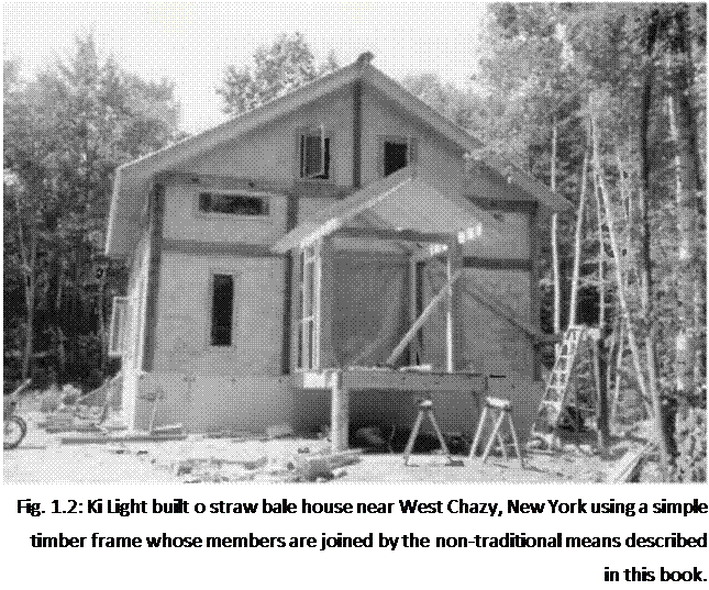
Подпись: Fig. 1.2: Ki Light built о straw bale house near West Chazy, New York using a simple timber frame whose members are joined by the non-traditional means described in this book. Esthetic appeal. Normally, timber frames are left exposed, either on the interior, the exterior, or, in many cases, on both sides of the wall, such as the guesthouses and the garage at Earthwood. With many of the professionally built contemporary timber frame houses, structural insulated panels are fastened to the outside of the frame, and the beautiful heavy timbers are left exposed on the interior, (see Sidebar on page 13) At some 16-sided cordwood homes, the heavy timbers are in evidence on the exterior, but not on the interior. Chapter 6 of my previous book Cordwood Building: The State of the Art [see Bibliography] contains a detailed description of this almost-round timber frame. The method is of most interest to cordwood masonry builders, and is not repeated in this work.

In all cases, the exposed timbers lend character, texture, and an esthetic sense of strength to the architecture. All of this translates into comfort, spiritual and otherwise.

Ease of construction. If you’ve never built anything before, you might actually find timber framing to be easier than conventional studding, which requires fairly exact tolerances for the application of sheetrock, plywood and the like. With timber framing, there are far fewer pieces to handle. And tolerances, at least in the post and beam frame, do not need to be quite so exact, particularly when the walls are infilled with natural materials. True, much of the work will require two people, but this is also true with stick-frame construction.

Economy. If you are buying from a local sawmill or a farmer, or if you are making timbers from your own trees, timber framing is almost certain to be more economical than buying finished lumber. When buying heavy timbers from a distant source, this advantage is lost and timber framing may become more expensive. The key to building anything economically by any method is to use local or indigenous materials.

A final note

My intention in writing and now in twice revising this book has been to assist designers and builders who are attempting to make beautiful buildings that endure. With the drawings, I have tried to describe the relationship among the parts of every common connection. Alternative approaches to popular details have been included as well. I have relied primarily on my own experiences but have also drawn significantly on the accounts of others. In order to build upon this endeavor, I encourage you, the reader, to let me know of your own observations and critical comments.

Please send them to me care of The Taunton Press,

PO. Box 5506, Newtown, CT 06470-5506 or via email to thallonarch@continet. com.

Hydraulics of the kingdom of Mari, on the middle Euphrates (IIIrd and IInd millennia BC)

About 2800 or 2900 BC, the Sumerians – or perhaps a people already established some­what to the north at Terqa – founded Mari, on the middle course of the Euphrates. The site is at the intersection of routes to the Syrian coast, near the outlet of the fertile valley of Khabur. This is not a village that has grown and evolved, but rather a “new city”. The region of Mari is completely arid, no agriculture is possible without irrigation. Yet 200 km to the north, at the toe of the Anti-Taurus mountains, one finds land that is naturally well watered. Therefore Mari must have been established where it is for reasons relat­ed to commerce and control of the waterway. The land of Sumer has to import raw mate­rial such as wood, stone, and metals. The early (and temporary) city of Habuba Kebira, further upstream, undoubtedly had the same needs. From the very beginning, Mari is a center of bronze metallurgy. Boats descending the Euphrates and the Khabur bring min­erals and charcoal to the city.[56]

Mari falls under the control of Sargon of Akkad around 2300 BC. Its period of greatest grandeur occurs under a dynasty of Bedouin origin (called Amorite), capital of a great kingdom of upper Mesopotamia between 1850 and about 1761 BC. In 1761 BC it sees its final destruction by the Babylonian Hammurabi, even though Zimri Lim, last king of Mari, had helped Hammurabi in his wars against Larsa, Esnuma, and Elam. The palace fire buried, and preserved to the present time, the clay tablets that comprise the archives of the last thirty years of the kingdom.

The city of Mari is essentially circular in shape, surrounded by a dike and wall. The city is 1 to 2 km distant from the Euphrates, for protection from floods and erosion. It is crossed by a canal that links it to the Euphrates at each end. This canal is 30 m wide,

and brings water to the city as well as providing access to the port of Mari.[57]

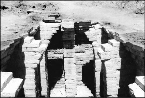
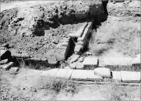
The city’s water supply is from the Euphrates, lifted into it by manual labor; women carry the water and fill the palace’s cistern (Figure 2.9). But in the palace of the IInd millennium BC there is also a network of brick conduits or pipes (Figure 2.10) that col­lects rainwater from the terraces to fill a reservoir.

Hydraulics of the kingdom of Mari, on the middle Euphrates (IIIrd and IInd millennia BC)

Figure 2.9 The cistern of the Mari palace – beginning of the IInd millennium BC (photo by the author).

In Chapter 1 we mentioned that Mari also benefited from a sort of drainage system, with sumps or cesspools for the drainage of rainwater and wastewater. This is evident from certain remains, as well as from palace texts:

“…On the subject of the sump, [….] according to the letter from my Lord, it is lined with asphalt from bottom to top. Over the layer of asphalt, there is a tar lining, and on top of that they put a coat of clay plaster.”

“After two rainstorms in succession, the sump was filled with water to a depth of a cane. The next day, they investigated it: 4 cubits of water had flown out. There remained 2 cubits, but they have already drained out ”[58]

Development of the land relies on major hydraulic works. Around 1850 BC, the sec­ond king of the Amorite Dynasty, Yahdun Lim, founds a fortress-city about a hundred

Hydraulics of the kingdom of Mari, on the middle Euphrates (IIIrd and IInd millennia BC)

Figure 2.10 Channels for capturing rainfall on terraces of the Mari palace, beginning of the IInd millennium BC (photo by the author).

kilometers to the north of Mari, on the right bank of the Euphrates upstream of its con­fluence with the Khabur. He gives his name to the city, and endows it with a canal:

“Yahdun-Lim, the son ofYaggid-Lim, king of Mari, of Tuttul and the land of Hana, the strong king who rules the banks of the Euphrates; Dagan proclaimed my royalty (…). I opened canals, water-lifters were no longer needed in my country. I built the Mari wall and I dug its moat. I built the wall of Terqa and I dug its moat. Moreover, in the burning lands, in a place of thirst no king had been able to build a city, I, alone, had the vision and built a city. I dug its moat. I named it Dur-Yahdun-Lim. Then I opened a canal and named it Isim-Yahdun-Lim… ”[59] [60]

From texts cited further on, one can estimate that this canal is about 35 km long, a length necessary for the canal, with its flat slope relative to the Euphrates, to “raise" the water above the river to provide gravity irrigation of the crops. Traces of the canal remain visible today, but only in its upstream reaches.

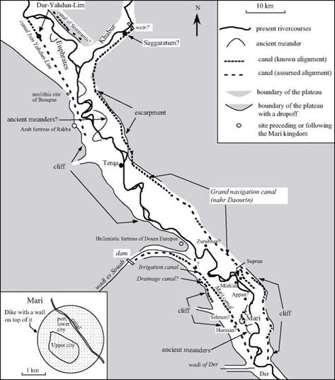
Field studies2 7 have uncovered traces of other important canals near Mari (Figure 2.11). There is a large irrigation canal, six to seven meters wide and 2.5 m deep, whose remains can be detected along a distance of17 km. It is not entrenched, but for the most part is constructed of fill on the alluvial terrace by means of massive dikes, 2.5 m high and 50 m wide. This is probably the Mari canal mentioned in the archives of the IInd millennium BC. Extracts that we cite further on suggest that the canal ends some ten kilometers downstream of Mari, and that it is supplied by an intake on the Euphrates in the valley of wadi es-Souab. But it is also quite possible that the canal dates from a time preceding these texts, having its origin in a small dam whose traces have been identified on wadi es-Souab, to the west of Mari. This wadi, one of the most important seasonal tributaries of the Euphrates, has particularly abundant springtime floods. The dam, 19 km from the confluence of the wadi with the Euphrates, is 450 m long, 2.5 m high, and has two spillways.[61] There is yet another canal that could have provided drainage, between the city and the foot of the cliff. Mari could not survive without some degree of agriculture, and such agriculture was impossible without irrigation. Therefore it is nearly certain that all these canals date from the founding of Mari, around 2800 BC.

Written communications[62] [63] [64] found in the Mari palace include numerous descriptions of the work necessary to maintain the irrigation system. The water intakes are often blocked by silt deposits and the canals themselves encumbered with sediments and veg­etation that must be cleaned out annually. “Barriers”, apparently comprising tree trunks and branches, are placed to protect the intakes and limit deposits in their vicinity. Let’s listen to Kibri-Dagan, the governor of Terqa, in extracts from two different messages: “As for the work on the canal of Isim-Yahdun-Lim that I had to undertake the fifth of the month of Abum, I undertook it. It is considerable. I am going to proceed with considerable dredging. At this canal, the barrier-muba/litum that diverts the clayey silt toward the river is no longer there, and this has caused the canal to narrow near the river. (…) With my work­ers from the area, I am working on the interior of the canal. In ten days I will have cleaned out the reeds and brush down to Terqa, and there where the canal has narrowed, I will open it up again. I will be sure the work is done solidly so that the irrigation water will be blocked nowhere and so that the people can avoid famine.’0^

“At the end of the month of Abum, I gathered the servile and common people of my district and together with districts of Mari and of Saggaratum, I set out to open the blockage of the canal of Mari. However, before working on the canal of Mari, I used up all the water of the canal Isim-Yahdun-Lim for the upstream district, saying to myself: before the fields of the countryside of Terqa are irrigated, once water is available, the (upstream) district must be able to drink so that later on there will be no basis for protest.’01

Hydraulics of the kingdom of Mari, on the middle Euphrates (IIIrd and IInd millennia BC)

Figure 2.11 Hydraulic works of the Mari kingdom, synthesis of archaeological and epigraphical research.

Other correspondence gives indications of the manpower available for this work. At this time, Terqa can mobilize 400 workers. But for major undertakings, the order of

2,0 workers can be assembled, as the governor of Mari, Bahdi Lim, explains:

“Tell my lord: thus speaks Bahdi-Lim, your servant. Concerning the wadi of Der (on the right bank, downstream), we got going on the dead (?) intake works and the diversion canal. The administrative scribes calculated the amount of work necessary. Beyond the dead intake works, there is the work needed for the diversion. A crew of 2,000 people, that’s not much! After thinking about it, we go to work only on the diversion. The work that we have under-

32

taken is good.”

The “barriers” mentioned above also play the role of raising the river’s water level at the intake to facilitate the outflow into the canal, without completely blocking the river. At this time there are six similar “barriers” on the Khabur designed to supply the irrigation canals. A letter from Yaqqim-Addu, governor of Saggaratum (whose supposed location is shown on Figure 2.11), describes these barriers and mentions a canal that pro­vides water to the left bank of the Euphrates from the Khabur as an important element of the region’s irrigation system:

“The Habur (i. e. the Khabur), like the canal of Isim-Yahdun-Lim and the canal of Hubur (on the right bank, the north portion of the canal of Mari?), is part of our irrigation system. The people who profit from this irrigation canal never undertake to maintain it, and they have not reinforced the weak spots. I had to take on six barriers (muballittum) — who else could assure they would be watched over? When one wants to take water for the ditches, right where the trunks form fences, it takes 3,000 bundles of brushwood to make a piled-up barrier. But this doesn’t raise the Habur (the Khabur) a single finger! One must put in posts to form the fence:

one makes brushwood during ten days: one then piles them up to form barriers. Today this sys-

33

tem is damaged: alas! I am leaving for Habur; I am going to assess the damages.”

Later in this same letter, Yaqqim-Addu asks his colleague Dahdi-Lim, in charge of Mari, to loan him manpower, lacking which the Khabur flood will cause major damage: “At the present time, the Habur (the Khabur) is in flood at four cubits: it has covered all flood – able places. The dike-kisirtum that is upstream of the breach, downstream of the muballittu that we built, Kibri-Dagan and myself, had slipped. I am going to rebuild it. The side, at pres­ent, slipped again. I undertook to rebuild it. Moreover, the breach that we had closed up has reopened: two arches, made of brushwood, were installed. These various efforts have been considerable and have exceeded my means; my Lord needs to give instructions to Bahdi-Lim so that he will send me 200 men so I can reinforce the weak points on the Habur. If a breach occurs in the aforementioned dike, no one will be able to close it.”

One should not be surprised at how difficult it is to maintain these canals. As we have seen above, the slope of a canal must be less than that of the river, if the canal is to be used to irrigate terraces higher than the valley floor. The flow velocity must therefore be lower than that of the river, which favors the deposition of suspended silts in the canal.

The texts from Mari also show that fish farming is practiced at the beginning of the IInd millennium BC. The abandoned arms of the Euphrates are clearly exploited for this purpose, and it is again Kibri-Dagan who tells us about it:

“Tell my Lord, thus speaks Kibri-Dagan, your servant. When the river flood returned, the pond of Zurubban swelled and became larger than normal. This made me fear for the fish: there is a risk that the fish will leave the pond toward the river. Now a hundred people must come to make the water of the pond go toward the river.”[65]

Another text that we should cite tells us of a maneuver that makes the canal of Mari temporarily navigable, to carry boats loaded with grain from the harvest. All the second­ary canal intakes were closed to raise the level in the main canal. But this turned out to be a catastrophe, since the rising waters caused the dike to rupture, just as the governor of Mari, Sumu Hadu (predecessor of Bhadi Lim) was taken to bed, sick:

“Tell my Lord, thus speaks Sumu-Hadu: one had retained the water in the direction of Der: because of the boats that must transport grain, one had blocked, from the upstream, (all) the irrigation ditches, and the water level thus rose (in the canal). But yesterday, at nightfall, in the end the water opened a breach upstream of the bridge that is the intake with the Balih (here, the Wadi Der), there where there is a water conduit (uncertain translation: a device allowing water diversion). Immediately, despite my sickness, I got up, I harnessed my asses, and I went to turn aside the waters by a derivation system. Then I came back to stop the water in the Balih (the wadi Der). Early in the morning, I undertook to repair the damage: I am going to rebuild the water conduit (?), after which I will get to work compacting the soil. This breach caused an opening of two canes from top to bottom, on a width of four canes. By the first watch of the night, I will have finished blocking this breach and I will be able (again) to let the water pass. My lord should not worry! Moreover, I wrote to the various localities that I had turned aside the water during the night. At Appan, Humsan and Shehrum, the water was held in and there was not the least rise. As for me, I will be dealing with the sickness that I have contracted for a year!’OJ

All of these documents show that the leaders had strong personal engagements in the maintenance of the irrigation system. They called on specialists, likely trained from father to son, for positioning the gates, for the operational regulation of the network. The regions of Terqa and Mari are not the only ones in which such water management is practiced; further upstream the Balih is used to irrigate the region of the city of Tuttul during the Amorite period.

Water Balance

For a better understanding of the qualitative and quantitative relationships between water and roads, the general interaction of road to water should first be established. The approach adopted here for this interaction analysis is by considering the water balance.

The relation between a road and water can be defined in system theory terms where input and output values are observed. Thus, the road and its pavement can be defined as a system into and out of which water flows. In normal conditions the input to the road pavement is represented by precipitation. Rainfall, or water due to thawing, infiltrates the pavement and flows through into the surrounding environ­ment. Reverse flow of surface or groundwater towards the pavement embankment is also possible.

The general water balance equation can be simply defined as

P = R – ETR + IR (2.1)

or

P = R – ETR + G + AS (2.2)

each term having units of volume/time/area [L/T] and where P represents the pre­cipitation, R is the surface runoff, ETR represents evapotranspiration, G is the deep percolation or the groundwater recharge, IR is the surface infiltration and AS is the water storage change (or the net volume flux, thus qout – qin) of the pavement structure or the embankment. When some external inflow, qext, to the system is present, the water balance equation is defined as

P + qext = R – ETR + G + AS (2.3)

The presence of external flow qext is particularly important when we want to define the water balance of a road that is interacting with its hinterland and, especially, remote water bodies.

The water balance of roads and embankments is complex, depending on the structure of the system and on the goals that have to be achieved with the water balance model. A conceptual water balance model of a pavement-embankment sys­tem is represented in Fig. 2.1.

BERM ROAD CUTTING

4————– M—————————————————————— ►

SLOPE SLOPE

•4————– ► 4———————————- ►

EMBANKEMENT TRENCH

4—————- ► 4——————- ►

Water Balance

Fig. 2.1 Conceptual model of water balance on pavement – embankment system. v = vertical, l = lateral, ca = carriageway, su = surfacing, rb = roadbase, sub = sub-base, sc = slope/cutting, t = trench, em = embankment and b = berm

The water balance of the road depends on the geometry of the road and on the course of the road through the land. The water balance differs for roads where the pavement is completely above the ground level from those roads where the pave­ment or the complete road is below surface of the ground or even in tunnels or covered galleries.

A detailed water balance model of the pavement addresses water flow for each pavement component. In Fig. 2.1, water balance components are defined for the car­riageway, surfacing, roadbase, sub-base and subgrade. Also reflected in this figure is the important influence on the water balance of the action of water flowing in the adjacent drainage ditches and on the slopes.

In general components of the water balance in the pavement can be divided into two general types: the vertical component (subscript v in Fig. 2.1) and the lateral component (subscript l in Fig. 2.1). Vertical components of the water balance rep­resent the recharge of, or loss from, the groundwater while the lateral components present the contribution to the total surface outflow from, or inflow to, the pavement system.

Between the Middle Euphrates and the Syrian coast: dams and canals from the IVth to the IInd millennium BC

The mysteries of Jawa: the oldest known dams, on the slopes of Kjebel Druze (Djebel el Arab) – end of the IVth millennium BC

The site of Jawa, a hundred kilometers to the northeast of Amman in Jordan, is an enig­ma. It is an arid zone, in a desert of rough black basalt. The only source of water, apart from very infrequent rains, is the winter flood of a seasonal watercourse that comes down from Djebel Druze, the wadi Rajil. The site is somewhat off the track of commu­nication routes, but on the other hand it is easily defendable. Jawa had some 2,000 to

3,0 inhabitants toward the middle or the end of the IVth millennium BC. In this region [50] [51] where there had never been any settlements before, and where there will not be any new ones for several hundred centuries to come, these people built a fortified walled city, a citadel in essence. A British expedition, led by Svend Helms, explored the site between 1973 and 1976, and postulated that these people were refugees or migrants from some urban culture.[52]

For their water supply, the inhabitants of Jawa built an elaborate system that fills reservoirs with the runoff of winter and spring rains, and also with water diverted from the wadi Rajil during the floods of November and May. Three weirs on the wadi Rajil divert water into stone-lined canals that are several kilometers long and convey flow to ten reservoirs (Figure 2.6). Some fifteen gates control the capture and distribution of water toward either the multiple reservoirs, or toward irrigated fields. Three of the reser­voirs (Nos. II to IV, with a total volume of 42,000 m3) supply the city itself. Several other smaller reservoirs, totaling some 10,000 m3, supply animal pens. Cistern No. I, upstream of the city, is dug into a cavity of basalt. Open-air reservoirs Nos. VII, IX, and X are downstream of the city. One of the reservoirs (No. IV on the figure) is formed by a true dam, 4.5 m high and 80 m long. The dam comprises two stone walls confining a central impermeable earth core that is two meters thick (Figure 2.7). A hydrologic study has shown that the storage of water from the two combined sources (rainfall plus floodwaters of the wadi) could supply 3,000 to 5,000 inhabitants and their animals for an entire year.[53] The people of Jawa had even begun to raise the dam to a height of 5.5 m, and to build another similar reservoir along the course of the wadi Rajil itself. But these projects were destined to remain unfinished, as the city was abandoned after only fifty years of existence. The nature of the catastrophe that led these people to return to their desert wandering remains unknown to this day.

The hydraulic know-how seen at Jawa is not an isolated example. Somewhat later, around 3000 BC, semi-nomadic shepherds settle at the foot of the same mountain, 80 km to the north. Although they are not former city-dwellers like their earlier neighbors at Jawa, these shepherds are driven by the same preoccupation with their security, since they build a wall around their encampment. And like the inhabitants of Jawa, as soon as they arrive they master the same hydraulic techniques. Here, at Khirbet el-Umbashi (Figure 2.8), they form a reservoir in the bed of the wadi itself by building a dam right to the foot of the city wall. This earth dam, 30 – 40 m long, is later raised (as at Jawa) to reach a height of 6 to 8 meters. This reservoir then stores water brought from the two wadis to the north through a three-kilometer canal, as well as water from other direct runoff. An oblique weir, two kilometers upstream on the wadi Umbashi, diverts water toward another very large reservoir (some 30,000 m3) developed in a natural depression bounded by massive levees that attain heights of 2 to 3 m and a base width of 25 m.

Between the Middle Euphrates and the Syrian coast: dams and canals from the IVth to the IInd millennium BC

Figure 2.6 The hydraulic system of Jawa – end of the IVth millennium BC (after Svend Helms, 1987).

Between the Middle Euphrates and the Syrian coast: dams and canals from the IVth to the IInd millennium BC

Between the Middle Euphrates and the Syrian coast: dams and canals from the IVth to the IInd millennium BC

Figure 2.6b. The upstream wall of the dam forming reservoir IV in Jawa, looking toward the east. In the background, one can see the wall of the upper city of Jawa (photo by the author).


Between the Middle Euphrates and the Syrian coast: dams and canals from the IVth to the IInd millennium BC

Figure 2.6c. The reservoir VI in Jawa, looking toward the west. In the background, one can see reservoir V, and on the right the upper city of Jawa (photo by the author).


Between the Middle Euphrates and the Syrian coast: dams and canals from the IVth to the IInd millennium BC

Figure 2.7 The dam for reservoir No. IV at Jawa; the oldest known dam (Helms, 1987b). Vogel (1991) gives a similar but slightly different reconstitution of this dam, with only two stone walls (the major ones), a downstream earthfill slope of 0.4 : 1, and a thinner upstream rock drainage layer.

Between the Middle Euphrates and the Syrian coast: dams and canals from the IVth to the IInd millennium BC

Figure 2.8 The hydraulic system of Khirbet el Umbashi – about 3000 BC – after Braemer, Echallier, and Taraqji (1996)

At a neighboring site, Hebariyeh (in today’s Lebanon) one again finds the same kind of development, with a large watertight reservoir fed by diversions along a wadi and canals several kilometers in length. Unlike the ephemeral urban establishment of Jawa, these last two sites survive until about 1500 BC.[54] One can find additional remains of canals that collect rainfall along hundreds of meters of length[55] at other sites more to the west along the shores of the Dead Sea, from the beginning of the IIIrd millennium BC.

These hydraulic works represent the oldest known dams. It is impossible for them to represent merely local and isolated inventions. How could the new settlers at Jawa or at Khirbet el Umbashi have known how to construct, then and there, such relatively highly evolved hydraulic systems without having known of similar projects before? Therefore it seems clear that the construction of weirs and dam-reservoirs on intermit­tent watercourses had already become a technique known throughout the region from the end of the IVth millennium BC. The oasis of Damascus, occupied from Neolithic times, could have been at the origin of these techniques – though nothing is known of it during the period that interests us here. It should be remembered as well that the middle of the IVth millennium BC is a period of expansion of the Sumerian civilization. Habuba Kebira, with its highly perfected sewers, arises on the Middle Euphrates around 3500 BC, then is abandoned at some later date that could be close to the time of the founding of Jawa. With the beginning of the IIIrd millennium BC comes the period of the found­ing of Mari.

Requirements for SMA Materials

A distinctive feature of stone matrix asphalt (SMA) components is their high quality. In this chapter we shall have a look at the requirements for those materials in various countries. Comparing them may be interesting because of the diversity of emphases different countries place on individual conditions.

Consequently, the following components will be subsequently discussed in detail:

• Aggregates

• Binders

• Stabilizers

• Reclaimed asphalt

• Other additives

5.1 REQUIREMENTS FOR AGGREGATES

The requirements for aggregates are quite diverse, and they chiefly concern fun­damental properties that influence the performance of SMA and are attributed to the size of the grains. This has given rise to a variety of requirements for particular fractions—some for coarse (active) aggregates and other for fine ones. The require­ments for fillers have been defined in Chapters 2 and 3.

One may find that almost everywhere these requirements center around the fol­lowing properties:

• Coarse aggregate: hardness (resistance to fragmentation or crushing), percentage crushed, shape of grains, polishing resistance, and resistance to external factors (e. g., water, frost, deicers)

• Fine aggregate: angularity, amount of dust, and absence of swelling frac­tions in dusts

• Fillers: stiffening properties—difference in softening points (SPs), absence of swelling fractions, and air voids in a compacted filler.

Taking into account the type of aggregate skeletons required for SMAs, the pri­mary property seems to be resistance to crushing. This resistance is often assessed using the very popular Los Angeles abrasion test (L. A. index). The range of the allowable LA index in national specifications typically varies from 20 to 30%; how­ever, many publications from North America reported that some successful SMAs have aggregates with LA index values that are greater than 30%.

In one report (Celaya and Haddock, 2006) the authors express their opinion that the LA index is not the only important property of coarse aggregates for SMA. Besides the LA index, one should take into account the Micro-Deval test, which is conducted using water[19] and the Strategic Highway Research Program (SHRP) Superpave Gyratory Compactor (SGC) compaction degradation. This difference between the LA index and Micro-Deval test can show the aggregates that are sensitive to crushing in the presence of water. Finally, the results from the LA index, Micro-Deval test, and SGC degradation test provide the best way to select suitable coarse aggregates for use in SMA mixtures. Comprehensive reviews of coarse aggregate test methods are avail­able in the published literature such as Fowler et al. (2006) and White et al. (2006).

In Germany, the Schlagzertrummerungswert (EN 1097-2, Part 6) method is used instead of or together with the LA index. In general, resistance to crushing is crucial and must be tested because the use of weak aggregates may result in poor perfor­mance of the whole layer (Figure 5.1).

For the fine aggregate portion, the most commonly specified property is angu­larity. This can be tested using different methods; common ones include the flow rate method as in European Standard EN 933-6 (results in seconds, shown as Ecs) or the measurement of voids in uncompacted aggregate as in AASHTO T 304 (results in % [v/v], known as fine aggregate angularity [FAA]). Obviously other methods are used and could also be good indicators of angularity. Johnson et al. (2004) have conducted interesting research to evaluate the influence of FAA and

image39

FIGURE 5.1 An example of the use of very weak aggregates in an SMA mixture; sample after wheel tracking test shows fractured aggregate particles. (Photo courtesy of Krzysztof Blazejowski.)

other variables on asphalt mix performance. That study confirmed that FAA is a good tool to predict dynamic modulus and rut resistance.

The requirements for filler, besides gradation, are focused on analyses of clay and silt in the filler and on the stiffening properties represented by an increase of the SP and Rigden voids. The specific areas of filler are gradually being withdrawn from specifications in some countries (e. g., Poland and Finland). Applications of different raw materials as fillers were described in Chapter 3. Some waste materials, such as coal fly ash, waste ceramics, and steel slag, have also been tested, and the results indicate a good potential for use in SMA (Muniandy et al., 2009).

The requirements for aggregates in selected countries are described throughout this chapter. The data are divided into two parts—that for CEN countries (mainly European Union) and that for the United States. A more comprehensive record of data would surpass the scope of this book.

Preliminary Development Phase

Two types of projects are considered here: (1) projects that involve studies outside the existing corridor or where a facility for more than one alternative mode of transportation may be involved, and (2) projects where feasible alternatives are limited to the existing corridor but did not qualify to pass directly to the design phase. The main difference between the two as far as processing is concerned is that the first group has not yet narrowed its alternatives down to feasible alternatives.

In each case, a project inventory is developed. This information includes historical sites; public recreational facilities; school, church, fire, and police districts; proposed development; land use; existing and other proposed transportation facilities; prelimi­nary traffic assignments; and other similar social, economic, and environmental features, which are pertinent to the area under study. Using this information as a guide, all pre­liminary alternatives are developed together with documentation of the anticipated effects on community, preliminary cost estimates, and other technical considerations. Advantages and disadvantages of each alternative are studied. Where appropriate, coor­dination with other modes is considered. The “no-build” alternative is also considered and provides a reference point for defining potential beneficial and adverse impacts. Public hearings are held to gain input from the local public in the affected areas. Following an evaluation of all input received, alternatives are weighed and only those considered to be feasible are forwarded to the next step. From this point on, all projects in the preliminary development phase are on the same path.

Among the environmental concerns which must be considered for each alternative are the following (see also Chap. 1):

Air quality. A study of the effect of a proposed transportation improvement on the quality of the air

Historic or prehistoric. A study of the effect of the proposed transportation improvement on historic or prehistoric objects or on lands or structures currently entered into the National Register or which may be eligible for addition to the National Register

Endangered species. A study of the effect of the proposed transportation improve­ment on rare or endangered plants or animals having national or state recognition Natural areas. A study of the effect of the proposed transportation improvement on natural areas designated as having regional, state, or national significance Parks and recreation. A study of the effect of the proposed transportation improvement on publicly owned parks, recreation areas, or wildlife and waterfowl refuges designated as having national, state, or local significance

Prime farmlands. A study of the effect of the proposed transportation improvement on farmlands with high productivity due to soil and water conditions or having other unique advantages for growing specialty crops

Scenic rivers. A study of the effect of the proposed transportation improvement on any scenic rivers of state or national significance

Streams and wetlands. A study of the effect of the proposed transportation improvement on streams and wetlands on project and abutting land areas

Water quality. A study of the effect of the proposed transportation improvement on the quality of live streams or bodies of water

The next step is a refinement of feasible alternatives. This requires additional work sufficient to prepare an environment document. This could include such items as approxi­mate construction costs; alignment and profile studies; typical section development; pre­liminary designs for geometric layout, drainage, right-of-way, and utilities; location of interchanges, grade separations, and at-grade intersections; preliminary bridge designs at critical locations; channel work; air, noise, and water studies; flood hazard evaluations; and other supplemental studies and right-of-way information. Once again, input is sought from the public sector through advertisement and public hearings.

Figure 2.1 shows the corridors for the feasible alternatives for an 11-mi relocation of U. S. 30 in Ohio (Ref. 13). The map is part of a study evaluating crossroad treatment for each alternative. Figures 2.2 and 2.3 show the projected crossroad treatments for the various alternatives. The options are (1) interchange, (2) grade separation, or (3) closing roads with cul-de-sacs. Since the proposed segment will be a limited-access highway, the option of at-grade intersection was not considered. Figures 2.4 and 2.5 show current and 20-year projected traffic volumes for all roadways. These are examples of maps used in the study of feasible alternatives.

After consideration of all the input and comparing the benefits and disadvantages of each alternative, the next step is to make a selection of the recommended alternative. This selection is certified by the state’s transportation director. Following approval of the environmental document, the project may proceed to the design phase.

Framing square

I learned to use the framing square when I was a carpenter in the Navy in the early ’50s. First introduced almost 1 50 years ago, the venerable framing square is still hard at work. Made of steel or aluminum, it has a 16-in. tongue and a 24-in. blade set at right angles to one another. Not an easy tool to carry in your toolbelt, it is neverthe­less handy for quickly checking if walls are perpendicular to each other when setting cabinets and for marking square across 2×12 joists.

I use small stair gauges with my framing square when laying out stairs (see the photo below). The gauges are simply screw clips that are fastened to the edge

Framing square

Stair gauges attach to a framing square and position it at any given angle.


Framing square

When you have a corner that’s out of square, you can check it with a T-bevel square. Place the square in the corner, adjust the handle until it fits flat against the wall, then tighten the wing nut. Transfer this angle to the material to be cut.


of the square, making it possible to mark the same angles on a stair stringer repeatedly.

Combination square

Most combination squares have a 12-in. blade marked off like a ruler with a slid­ing head. One side of the head is used to lay out a 90° angle, and the other side is used to lay out a 45° angle. [1]

T-bevel square

A T-bevel square has a blade that pivots and slides on a handle and can be locked in any position by a wing nut. I have one with an 8-in. blade, but many lengths are available.

This is an effective tool for fitting mater­ial to an odd angle. For example, you can use it to fit a shelf into a corner that is not 90° (see the photo above). First place the square in the corner with the blade against one wall. Then adjust the handle until it fits flat against the wall and tighten the wing nut. Nowyou can transfer this angle to the shelving, mark­ing a precise cut. What makes the T-bevel square especially handy is that you can bring it right over to the chop – saw and use it to help adjust the angle of the blade exactly (unplug your saw before doing this).

Подпись: Tape measures are available in a wide variety of sizes. Most carpenters use either a 16-ft. or 25-ft. tape.
Drywaller’s T-square

A drywaller’s T-square is shaped like a "T" with a 22-in. tongue and a 48-in. blade that are both marked with inch scales. While usually used to mark sheets of drywall, this square is also a good tool to use when marking other sheet goods (like plywood) or doors for cutting. Just press the tongue along a square edge and mark along the long blade.

Treat the T-square with kindness. If you drop it, you can easily knock it out of square. To check for square, lay it across a sheet of plywood and mark along the
blade side. Then turn the square over and mark again. If the blade is not on the line, the tool is not square.