WOOD CONSTRUCTION CONNECTORS

Wood construction connectors are commonly called Simpson™ Strong-Ties™ after the company that popularized them. For a complete overview of available connectors from Simpson, go to www. strongtie. com. Professionals swear by these ingenious connectors for three main reasons.

►They offer wood-to-wood connections superior to most traditional construction methods. For example, unlike toenailing, metal connectors are unlikely to split lumber ends or loosen under stress. These galvanized steel connectors are strong and durable.

►They greatly strengthen joints against earthquakes, high winds, and other racking forces. They can tie rafters to walls, walls to floor platforms, and the substructure to its foundation.

►Most can be attached to existing framing, a great boon to renovators, and in many cases steel connectors are the only cost-effective way to bolster the existing structure and tie additions to the original structure.

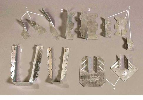
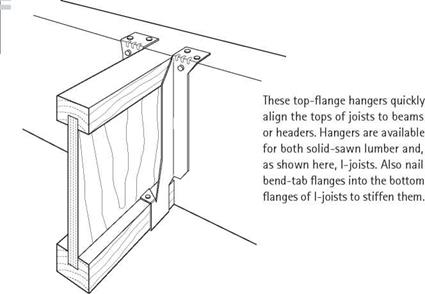
Joist hangers are indispensable in renovation when you want to add joists but can’t end-nail, either because access is limited or because you’re using engineered lumber, which is too thin in cross section to end-nail successfully. (Sawn-lumber joists and I-joists require different hangers.) There are joist-hangers for single joists, double joists, 4×10 beams, joists intersecting at a 45° angle, and so on. You also have the choice of face-mount or top-flange hangers. Top flanges are popular because they effortlessly align the tops of I-joists with the top of a header or beam.

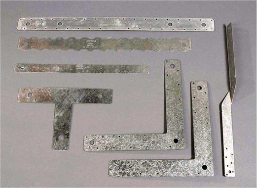
Strap ties come in myriad shapes—tees, right angles, twists—but all help keep joints from pulling apart. Install flat strap ties where wall


6


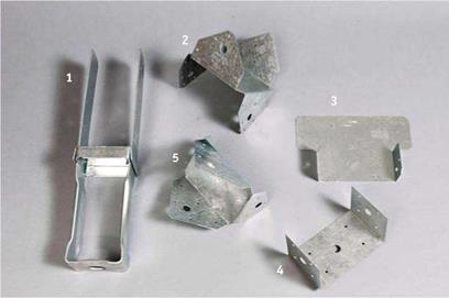
Wood construction connectors. (Contractors generally refer to them by their Simpson catalog numbers.) I, H2.5, H4, and H8 hurricane ties; 2, L90 reinforcing angle; 3, LS70 skewable angle (bend one time only); 4, A35, A35F, and A34 framing angles; 5, U410 face-mount hanger for 4×10 beam (or double 2x10s);

6, LU28 face-mount hanger for 2×8 joist; 7, H10 and H1 hurricane ties.


image127

Straps, ties and angles. Clockwise, from lowerleff;T-strap (post-to – beam connector), SST22 light-gauge strap, ST6224 (24-in.) strap, MST24 heavy-gauge strap, twist strap, and heavy-gauge L-straps.


image128

image129

Подпись: Framing angles are used extensively to reinforce wood connections at 90° intersections. For seismic strengthening and on shear walls, framing angles help prevent floor framing from slipping off walls and supports during an earthquake. Hold-downs are massive steel brackets that anchor framing to foundations and, when used with long threaded rods, join framing on different floors. When retrofitting to a foundation, use epoxy to attach hold-down bolts to concrete, as shown in the bottom left photo on p. 219.
Подпись: I Simpson Top-Flange Hanger
Подпись: TECO Nans When attaching metal connectors, wear safety glasses and use only the special nails supplied by manufacturers, commonly called Teco nails after an early manufacturer. These nails are harder and squatter than regular nails and are less likely to shear under pressure.

plates are discontinuous or where rafter pairs meet at the ridge. Strap ties also keep floor plat­forms from separating, much as shear walling does. Hurricane ties, or twist straps, have a 90° twist to join rafters to top plates, thereby fighting the tendency of roofs to lift during a strong cross­wind. T-straps and L-straps are face-nailed to members joining in a right angle.

Clips vary by function. H-clips are an alternative to solid blocking when installing roof sheathing. They also act as JL-in. spacers so roof sheathing can expand. Drywallclips allow you to eliminate some blocking in corners, but it’s best to use these clips sparingly; solid blocking is much stronger. Deck clips are nailed to deck joists, and then 2×4 decking is driven onto the sharpened

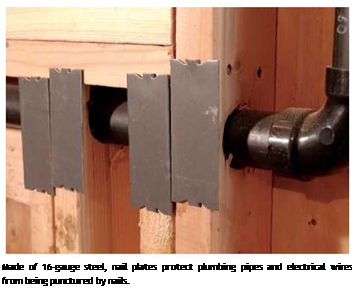
Подпись: 1111 Miscellaneous metal connectors are often needed. Where you absolutely must notch stud edges to accommodate plumbing, a metal shoe plate reinforces the stud and protects the pipe from errant nails. Speaking of protection, this discussion would be incomplete without mentioning nail plates, which protect wires and pipes from stray nails when finish walls go up. Adhesives, Caulks, and Sealants Common adhesives, caulks, and sealants look the same, but their formulations are complex and carefully formulated for specific materials and expected conditions. They all generally come in 10-oz. cartridges that fit into an applicator (caulk- Подпись: Made of 16-gauge steel, nail plates protect plumbing pipes and electrical wires from being punctured by nails. Подпись: Post caps resemble a pair of U-brackets set at right angles to each other: One U, upside down, straddles the top of the post, while the other, right side up, receives the beam on which the joist will sit.Подпись: Caps and bases. 1, A CBSQ44 post base anchors a 4x4 to concrete; 2, BC6 post cap and base; 3, AC6 post-to-beam connector, which can be attached after the members are in place; 4, BC460 half-base; 5, BC46 post cap and base.

Подпись: point of the clip. Thus you can lay down decking without having to face-nail it; the clip also acts as a spacer so that water can clear. Post bases and caps provide strong connections while elimi-nating the need to toenail posts, which tends to split them. Post bases are typically set in concrete, with posts then bolted or nailed to the base. Bases also reduce post rot, for their raised standoffs elevate the post and so double as a moisture shield.
Подпись: PROTIP Choosing the right adhesive is tough. These compounds are cutting-edge chemistry. Formulations of familiar brands change often—and often without warning. So here are three commonsense tips: (1) Test a tube, if at all possible, before you buy a case of any adhesive; (2) get friendly with the resident adhesive expert at the lumberyard, who may have gotten a lot of feedback from the field; (3) "but it's cheap" is always a fool's bargain.

image131ing gun). You then simply cut the cartridge noz­zle to the desired diameter and squeeze the long pistol-grip trigger to lay down beads of the stuff.

CONSTRUCTION ADHESIVES

Construction adhesives bond to a remarkable variety of materials, including standard lumber, treated lumber, plywood and OSB panels, dry – wall, wall paneling, rigid insulation, concrete and masonry, tile, metal, and glass.

Construction adhesives are a boon to builders. Instead of nailing sheathing every 6 in. around panel edges and every 10 in. "in the field,” build­ers using adhesives need nail only every 12 in. Being flexible, adhesives fill surface irregularities and double as sealants. Structurally, panels bond­ed with adhesive are stiffer and capable of bearing greater loads than panels that are only nailed. Floor sheathing and stair treads so bonded are far less likely to flex, pop nails, or squeak. Drywall ceilings bonded with adhesives do a better job of deadening sound and cutting air infiltration.

A number of considerations should determine your choice of adhesives: the materials being joined, strength, durability, flexibility, shrinkage, conditions on the work site (especially tempera­ture and humidity), workability, curing time, ease of cleanup, and odor.

Most solvent-based adhesives create water­proof bonds and clean up with mineral spirits. Most water-based adhesives create water-resist­ant bonds and clean up with water. Because sol­vent-based adhesives often have strong odors that are problematic for people with chemical sensi­
tivities, there’s a growing selection of solvent – and odor-free adhesives—and whole lines of environment-friendly adhesives.

Fortunately, you don’t need to be a chemist to find a suitable adhesive. Many manufacturers now offer on-line interactive product selectors on their Web sites, such as the Titebond™ company (www. titebond. com). Choose the adhesive fea­tures you want, and the on-line selector will choose the most appropriate product. Once you pick an adhesive, download product specs and study them: particularly application, curing times, cleanup, and safety advice.

A POTPOURRI OF ADHESIVES

Here’s a primer on common adhesives you may encounter.

Polyurethanes are often touted as all-purpose waterproof adhesives, capable of bonding wood, stone, metal, ceramics, Corian®, and so on. Strong, versatile, and easy to use, polyurethanes are favorites with builders and woodworkers. Since they require some moisture to set up, it’s possible to glue up wet wood with polyurethanes. In fact, you should moisten extremely dry wood joints before application.

Acrylics are good for outdoor use. They’re quick drying, strong, and completely waterproof.

Epoxy resins are famous for their strength. Typically mixed from two components, epoxies can bond to materials on which almost nothing else will—that is, when the surface areas to be bonded are small or when dampness is extreme. Epoxy products are especially important in foun­dation repairs and seismic strengthening (for more information, see Chapter 10).

Resorcinol is a strong, waterproof glue used by boatbuilders, among others. Like epoxy, it is a two-part glue that is very difficult to remove once it has set. Wood parts fastened with resorcinol will probably shear before the glue itself does.

Styrene-butadiene is a good all-purpose exterior and interior glue for joining materials of low porosity, such as tile and masonry.

Contact cement is commonly used to bond veneers and laminates to a base material, often particleboard. Once the sheets come in contact with each other, separation or realignment is all but impossible.

Hot-melt glues are applied with an electric glue gun and are excellent for tacking surfaces quickly. However, strength and water resistance are only so-so, because hot glues are applied only as spots. Still, they’re great for building templates out of thin plywood strips (see Chapter 13).

SEALANTS AND CAULKS

As noted in "Sticky Names,” above, sealants and caulks do pretty much the same thing: fill gaps, keep moisture at bay, and reduce air infiltration. Sealants tend to last longer, perform better, and cost more. In this brief section, we’ll look at the strengths and weaknesses of three major types of caulk.

Although caulks aren’t quite so diverse as con­struction adhesives, they do have varying formu­lations and properties. For specifics, go on-line or visit your lumberyard.

Silicones are arguably the most durable and most water resistant of any caulk. They are espe­cially suitable for window glazing and slick bath­room and kitchen surfaces.

► Advantages: Silicones are incredibly tenacious on nonporous materials like glass, glazed ceramic tiles, and metal. There’s little shrinkage, and they can be applied at -40°F. Silicone sealants specified for metal flue pipe function at 500°F. And silicones have the best long-term flexibility, UV resistance, and weather – ability. Also, molds won’t grow on them.

► Disadvantages: Silicones are messy to work with; wear rubber gloves to protect your skin. Once silicones have cured, it’s almost impossible to remove them. Plus, they are bond breakers—that is, because nothing will stick to an area they’ve tainted, think twice about trying them on wood, concrete, or other porous sur­faces they don’t adhere well to. Avoid inhaling acetoxy silicones, and don’t use them on metal because they’ll corrode it. Pure silicones can’t be painted, although siliconized acrylics can.

Polyurethanes are versatile multipurpose caulks but are not as tenacious as silicones.

► Advantages: Because they attach equally well to wood, masonry, and metal, they’re good for caulking joints where dissimilar

materials meet. Polyurethanes won’t corrode metal. They’re easy to work, though polys get pretty stiff as temperatures approach freezing. Shrinkage is negligible. They’re great for sky­light flashing and metal roofs. And they can be painted. Also, they’re easier to work than sili­cones, even though solvent based.

► Disadvantages: Polyurethanes have poor UV resistance, though additives or painting can improve that dramatically. While they are a good all-purpose caulk, they don’t have the durability or shelf life of silicones.

Latex acrylics are a good balance of perform­ance, price, and workability.

► Advantages: Latex acrylics are water based, hence nontoxic, largely odor free, and
very easy to apply (you can shape caulk joints with your finger). They clean up with soap and water. They adhere well to a range of materials, have good UV resistance, and can be painted. Durable once cured, they are best used in protected areas in temperate climates. They are paintable.

► Disadvantages: Expect significant shrinkage (up to 30 percent) and long curing times. Although good as bedding caulk under door or window casing, they’re iffy as exterior caulk or shower and tub caulk. Properties vary widely from product to product. Although some manufacturers tout spectacular per­formance specs, check out on-line contractor chat groups for real-life performance ratings.

WOOD CONSTRUCTION CONNECTORS

Floor Joists*

30-lb. Live Load 10-lb. Dead Load L/360

Span (feet and inches)

2×6 2×8 2×10 2×12

Spacing on Center

or Group

Grade

12in.

16 in.

19.2 in.

24 in.

12 in.

16 in.

19.2 in.

24 in.

12 in.

16 in.

19.2 in.

24 in.

12 in.

16 in.

19.2 in.

24 in.

Douglas

Sel. Struc.

12-6

11-4

10-8

9-11

16-6

15-0

14-1

13-1

21-0

19-1

18-0

16-8

25-7

23-3

21-10

20-3

fir-

No. 1 & Btr

. 12-3

11-2

10-6

9-9

16-2

14-8

13-10

12-10

20-8

18-9

17-8

16-5

25-1

22-10

21-4

19-1

larch

No. 1

12-0

10-11

10-4

9-7

15-10

14-5

13-7

12-4

20-3

18-5

16-9

15-0

24-8

21-4

19-6

17-5

No. 2

11-10

10-9

10-1

9-3

15-7

14-2

13-0

11-8

19-10

17-5

15-11

14-3

23-4

20-3

18-6

16-6

No. 3

9-11

8-7

7-10

7-0

12-7

10-11

10-0

8-11

15-5

13-4

12-2

10-11

17-10

15-5

14-1

12-7

Douglas

Sel. Struc.

11-3

10-3

9-8

8-11

14-11

13-6

12-9

11-10

19-0

17-3

16-3

15-1

23-1

21-0

19-9

18-4

fir

No. 1

11-0

10-0

9-5

8-9

14-6

13-2

12-5

11-6

18-6

16-10

15-10

14-5

22-6

20-6

18-9

16-9

(South)

No. 2

10-9

9-9

9-2

8-6

14-2

12-10

12-1

11-3

18-0

16-5

15-5

13-10

21-11

19-8

17-11

16-1

No. 3

9-8

8-5

7-8

6-10

12-4

10-8

9-9

8-8

15-0

13-0

11-10

10-7

17-5

15-1

13-9

12-4

Hem-fir

Sel. Struc.

11-10

10-9

10-1

9-4

15-7

14-2

13-4

12-4

19-10

18-0

17-0

15-9

24-2

21-11

20-8

19-2

No. 1 & Btr

. 11-7

10-6

9-10

9-2

15-3

13-10

13-0

12-1

19-5

17-8

16-7

15-5

23-7

21-6

20-2

18-3

No. 1

11-7

10-6

9-10

9-2

15-3

13-10

13-0

12-1

19-5

17-8

16-7

14-10

23-7

21-1

19-3

17-2

No. 2

11-0

10-0

9-5

8-9

14-6

13-2

12-5

11-4

18-6

16-10

15-6

13-10

22-6

19-8

17-11

16-1

No. 3

9-8

8-5

7-8

6-10

12-4

10-8

9-9

8-8

15-0

13-0

11-10

10-7

17-5

15-1

13-9

12-4

Spruce-

Sel. Struc.

11-0

10-0

9-5

8-9

14-6

13-2

12-5

11-6

18-6

16-10

15-10

14-8

22-6

20-6

19-3

17-11

pine-fir

No. 1

10-9

9-9

9-2

8-6

14-2

12-10

12-1

11-3

18-0

16-5

15-5

14-1

21-11

19-11

18-3

16-3

(South)

No. 2

10-5

9-6

8-11

8-3

13-9

12-6

11-9

10-10

17-6

15-11

14-9

13-3

21-4

18-9

17-2

15-4

No. 3

9-3

8-0

7-3

6-6

11-8

10-1

9-3

8-3

14-3

12-4

11-3

10-1

16-6

14-4

13-1

11-8

Western

Sel. Struc.

10-9

9-9

9-2

8-6

14-2

12-10

12-1

11-3

18-0

16-5

15-5

14-3

21-11

19-11

18-6

16-6

woods

No. 1

10-5

9-6

8-11

8-0

13-9

12-4

11-4

10-1

17-5

15-1

13-10

12-4

20-3

17-6

16-0

14-4

No. 2

10-1

9-2

8-8

8-0

13-4

12-1

11-4

10-1

17-0

15-1

13-10

12-4

20-3

17-6

16-0

14-4

No. 3

8-5

7-3

6-8

5-11

10-8

9-3

8-5

7-6

13-0

11-3

10-3

9-2

15-1

13-1

11-11

10-8

* Design Criteria: Strength – 30 lbs. per sq. ft. live load, plus 10 lbs. per sq. ft. dead load. Deflection – Limited in span in inches divided by 360 for live load only. This table is used courtesy of Western Wood Products Association (www. wwpa. org) and is excerpted from Western Lumber Span Tables of Floor and Ceiling Joists and Roof Rafters. For more information about lumber grades, see pp. 47 and 48.

Syria-Palestine in the IInd millennium BC

The city of Ugarit, on the northern Syrian coast (several kilometers to the north of the present-day Lattaquieh), has been occupied since very early times. It served as a mar­itime port for trade with Cyprus and Crete in the context of commerce among Mesopotamia, Mari, Aleppo, Ebla and the Mediterranean, and then as a port of the Hittite Empire of Anatolia. The city knew a period of great prosperity from the IInd mil­lennium BC until its final destruction in 1200 BC by the Sea People. The city is built on high ground, using wells for its primary water supply. As at Mari, rainwater is cap­tured on terraces and brought through gutters and vertical drops to the cisterns of hous – es.[72] The city is surrounded by two small temporary watercourses, the nahr ed-Delbe and the nahr Chbayye, on each of which there is a small dam; the dam on the nahr ed – Delbe is described in detail by Yves Calvet and Bernard Geyer (1994). The originality of this structure resides in its movable beams or stoplogs that can be removed to allow floods to pass. This is the first evidence of such technology that eventually became widespread.

More to the south, on the eastern slopes of the Anti-Lebanon mountains, is the city of Damascus. The city’s water-resource infrastructure is developed toward the middle or end of the IInd millennium BC, under the control of the Arameans. Two canals flow out of the Barada, the perennial river on which Damascus depended from Neolithic times. The system is eventually completed by the Romans and the Arabs (Figure 7.6) and remains operational to this day.

In discussing great cities and their infrastructures we must include Jerusalem. In the 12th or 13th centuries BC the Canaanites constructed a 537-m long tunnel to provide access, during sieges, to a reservoir on the flanks of a hill that is fed by an intermittent spring called Gihon (today called the “fountain of Marie”). Later, around 700 BC, Ezechias tapped this spring through an underground canal feeding a basin to the south of the city, known as the Pool of Siloam.[73]

The Zagros Mountains and their foothills from the 8th to 7th centuries BC: dams, aqueducts, and water supply for cities

We have seen that from the 13th century BC the political situation becomes very cloudy in all the Syro-Mesopotamian region. New powers rise to the east and north of the old lands of Sumer and Akkadia, at the foot of the Zagros mountains. The new power cen­ters move from the region of Susa to the east, up the course of the Tigris (Assyria) before returning to the east with the Persians. The incubators of these new powers are valley, hill and mountain regions whose springs and streams can be developed to provide high – quality water for the settlements.

Variance, standard deviation, and coefficient of variation

The spreading of a random variable over its range is measured by the variance, which is defined for the continuous case as

/

TO

(X – fZx)2 fx(x) dx (2.36)

-TO

The variance is the second-order central moment. The positive square root of the variance is called the standard deviation ax, which is often used as a measure of the degree of uncertainty associated with a random variable.

The standard deviation has the same units as the random variable. To com­pare the degree of uncertainty of two random variables with different units, a dimensionless measure ^x = ax/^x, called the coefficient of variation, is useful. By its definition, the coefficient of variation indicates the variation of a random variable relative to its mean. Similar to the standard deviation, the second- order L-moment Л2 is a measure of dispersion of a random variable. The ratio of Л2 to Л1, that is, t2 = k2/k1, is called the L-coefficient of variation.

Three important properties of the variance are

1. Var(a) = 0 when a is a constant. (2.37)

2. Var(X) = E(X2) – E2(X) = ^ – ii2x (2.38)

3. The variance of the sum of several independent random variables equal the sum of variance of the individual random variables, that is,

Var f Y akXЛ = Y a (2.39)

k = 1 ) k = 1

where ak is a constant, and ak is the standard deviation of random variable Xk, k = 1,2,…, K.

Variance, standard deviation, and coefficient of variation

Example 2.11 (modified from Mays and Tung, 1992) Consider the mass balance of a surface reservoir over a 1-month period. The end-of-month storage S can be computed as

in which the subscript m is an indicator for month, Sm is the initial storage volume in the reservoir, Pm is the precipitation amount on the reservoir surface, Im is the surface-runoff inflow, Em is the total monthly evaporation amount from the reservoir surface, and Tm is the controlled monthly release volume from the reservoir.

It is assumed that at the beginning of the month, the initial storage volume and total monthly release are known. The monthly total precipitation amount, surface-runoff inflow, and evaporation are uncertain and are assumed to be independent random variables. The means and standard deviations of Pm, Im, and Em from historical data for month m are estimated as

E (Pm) = 1000 m3, E (Im) = 8000 m3, E (Em) = 3000 m3 a (Pm) = 500 m3, a (Im) = 2000 m3, a (Em) = 1000 m3

Determine the mean and standard deviation of the storage volume in the reservoir by the end of the month if the initial storage volume is 20,000 m3 and the designated release for the month is 10,000 m3.

Solution From Eq. (2.31), the mean of the end-of-month storage volume in the reservoir can be determined as

E ( Sm+1) = Sm + E ( Pm) + E (Im) – E ( Em) — Tm

= 20, 000 + 1000 + 8000 – 3000 – 10, 000 = 16, 000 m3

Since the random hydrologic variables are statistically independent, the variance of the end-of-month storage volume in the reservoir can be obtained, from Eq. (2.39), as

Var( Sm+1) = Var( Pm) + Var( Im) + Var( Em)

= [(0.5)2 + (2)2 + (1)2] x (1000m3)2 = 5.25 x (1000m3)2

The standard deviation and coefficient of variation of Sm+1 then are

a(Sm+1) = V525 x 1000 = 2290m3 and Q(Sm+1) = 2290/16,000 = 0.143

Curbs

The type of curb and its location affect driver behavior patterns, which, in turn, affect the safety and utility of a road or street. Curbs, or curbs and gutters, are used mainly in urban areas. They should be used with caution where design speeds exceed 40 mi/h (64 km/h). Following are various reasons for justifying the use of curbs, or curbs and gutters:

• Where required for drainage

• Where needed for channelization, delineation, control of access, or other means of improving traffic flow and safety

• To control parking where applicable

Types of Curb. There are two general categories of curbs: barrier curbs and mount­able curbs. Barrier curbs are relatively high [6 in (0.15 m) or more] and steep-faced. Mountable curbs are 6 in (0.15 m) or less in height and have flatter, sloping faces so that vehicles can cross them with varying degrees of ease. Figure 2.29 (Ref. 14) shows various curb designs that are commonly used on roadways. Types 1, 3, and 4 are examples of mountable curbs and are used for channelizing traffic, especially in islands and medians. Types 2 and 6 are barrier curbs used along pavement edges in urban areas and are designed to handle drainage more efficiently. Types 7 and 8 are tall barrier curbs designed to provide a more positive traffic barrier than the others. Type 7 is used as an alternate for guiderail in low-speed urban situations.

Position of Curb. Curbs are normally used at the edge of pavement on urban streets where the design speed is 40 mi/h (64 km/h) or less. Curbs at the edge of pavement have an effect on the lateral placement of moving vehicles. Drivers tend to shy away from them. Therefore, all curbs should be offset at least 1 ft (0.3 m) and preferably 2 ft (0.6 m) from the edge of the traffic lane. Where curb and gutter are used, the standard gutter width is 2 ft (0.6 m).

On roads where the design speed exceeds 40 mi/h (64 km/h), curbs should be used only in special cases. Special cases may include, but are not limited to, the use of curb to control surface drainage or to reduce right-of-way requirements in restricted areas.

Curbs

Edge of groded shoulder Portion of volley In depressed aiedl<


‘-B


Treoted Shoulder


Подпись: 143

СгомоV#r povement Slope t as mo In По* profile.


SECTION Д-Д


Dimensions Applicable toVarying Median Demands

M, ft

D, in

R-l, ft

R-2, ft

84

17.25

24.87

55.20

60

11.50

16.31

35.24

50

9.13

12.73

26.93

40

6.75

9.16

18.61


0.04


0.04


Tv-Ospresslon


ДВДЕ


J


Curbs

SECTION B-B


CurbsCurbs

Curbs

FIGURE 2.28 Design for U-turn median opening. Conversion: 1 ft = 0.305 m. (From Location and Design Manual, Vol. 1, Roadway Design, Ohio Department of Transportation, with permission)

Curbs

‘Asphalt’concrete [ Base J


TYPE /


• Bull Joints shell be provided between combined cu/b-and-guller and new rigid pavements. with lit bars or hoot bolts provided at five foot Intervals. Combined curb-ond-gutter shell be tied to existing rigid pavements wllh expansion hoot bolls spaced at five foot Intorvols. if the combined curb-ond-gulfer adjoins a new rigid base or on existing rigid base or povemeni that Is to be surfoced with bituminous malerlol. a bull Jolnl shall be provided and tie bars.’hoot bolls or expansion hoot bolls shall be omitted.


TYPE 5


TYPE 2


TYPE 4


Подпись: 144
Curbs

CurbsCurbsCurbs

When it is necessary to use curbs on roads where the design speed is over 40 mi/h, they should not be closer to the traffic than 4 ft (1.2 m) or the edge of the treated shoulder, whichever is greater.

Curb/Guiderail Relationship. If curbs are used in conjunction with guiderail on roads having a design speed in excess of 40 mi/h (64 km/h), the face of curb should preferably be located either at or behind the face of guiderail. Under no conditions should the face of curb be located more than 9 in (0.23 m) in front of the face of rail. This restriction is necessary to prevent a vehicle from “vaulting” over the rail or strik­ing it too high to be contained. Although guiderail is not normally used on curbed roadways having design speeds of 40 mi/h (64 km/h) or less, the same criteria used for higher-speed roadways should apply. Where this is not feasible or practical, the curb may be placed in front of the rail. Regardless of the design speed of the roadway or the placement of the curb, the face of guiderail should not be located closer than 4 ft (1.2 m) to the roadway.

Curb Transitions. Curb and raised median beginnings and endings should be tapered from the curb height to 0 in (0 m) in 10 ft (3 m). When an urban-type section with curbs at the edge of pavement changes to a rural-type section without curbs, the curb should be transitioned laterally at a 4:1 (longitudinal:lateral) rate to the outside edge of the treated shoulder, or 3 ft (0.9 m), whichever is greater. When a curbed side road intersects a mainline that is not curbed, the curb should be terminated no closer to the mainline edge of pavement than 8 ft (2.4 m) or the edge of the treated shoulder of the mainline, whichever is greater.

Interchange Elements

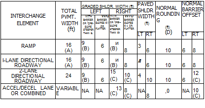
Cross-section information pertaining to interchange elements, such as ramps and directional roadways, is given in Fig. 2.26. This information includes pavement and shoulder dimensions for acceleration-deceleration lanes, one – and two-lane directional roadways, and medians between adjacent ramps. Notice that for a single-lane ramp, the shoulder and guiderail offset distances are greater on the driver’s right-hand side than on the left. This is to provide more width for drivers to pull over in emergencies and to allow people a better opportunity to go around disabled vehicles.

2.3.2 Medians

A median is a desirable element on all streets or roads with four or more lanes. The principal functions of a median are to prevent interference of opposing traffic, to provide a recovery area for out-of-control vehicles, to provide areas for emergency stopping and left turn lanes, to minimize headlight glare, and to provide width for future lanes. A median should be highly visible both day and night and in definite contrast to the roadway.

Width. The width of a median is the distance between the inside edges of the pave­ment. See Fig. 2.27 for examples of various medians. The width depends upon the type of facility, topography, and available right-of-way. In rural areas with flat or rolling terrain, the desirable median width for freeways is 60 to 84 ft (18 to 26 m). Although the minimum median width is normally 40 ft (12 m), narrower medians may be used in rugged terrain. A constant-width median is not necessary, and in fact,

Lateral clearances, ft


Vertical clearance over surfaced roadway, ftc


On bridgea


Traffic

Design year
ADT


Rural


Under bridge^7


Functional

class


Urban,

minimum


Preferred


Minimum


Minimum


Preferred


Minimum


Preferred


Interstates,

All

Right, 12а’

Right, 14^g

Freeways and

Left, ¥■•

Left, 6

expressways

Arterial s

> 4000

W

12

2001-4000

¥

10

1001-2000

&>

8

400-1000

&’

8

< 400

4

6

Collectors

> 4000

8"’

10

2001-4000

4 m

8

1001-2000

4?я, я

6

400-1000

4»г, я

4

< 400

4 m, o

4

Locals

> 4000

8"’

10

2001-4000

3

8

1001-2000

3

6

400-1000

3

4

< 400

2

4


16.5й


17.0


.Й л

£ п


16.5й


17.0


•9

H

л

<3

43

3

о


00 О

К, 8


Подпись: 138

14.5


15.0


Interchange Elements


14.5


15.0


и


Conversion: 1 ft = 0.305 m.

"Distance measured from edge of the traveled lane to face of curb or railing if no curb is provided.

^Distance measured from edge of traveled lane to face of walls or abutments and piers.

cTo minimize structure cost, design tolerances for clearances are plus 4 in, minus 0 in. Sign supports and pedestrian structures have a 1 – ft additional clearance. Clearances shown are over paved shoulder as well as pavement width.

dli bridge is considered to be a major structure having a length of 200 ft or more, the width may be reduced, subject to economic studies, but to no less than 4 ft.

eWhere the truck DDHV is 250 or less, may be reduced 2 ft.

/Where the truck DDHV is 250 or less, the right shoulder width may be reduced 2 ft.

AVhere concrete barrier is used on the approach slabs or in advance of the bridge, the preferred shoulder width will equal the minimum shoulder width.

hA 16.5-ft minimum vertical clearance applies to all rural sections and the single designated route in urban areas. On other urban routes, not on the single designated route, the vertical clearance should not be less than 15.5 ft.

‘If 6 or more lanes, provide 12 ft width. Where truck DDHV is 250 or less, the left shoulder bridge width may be reduced by 2 ft.

;If 6 or more lanes, provide 14 ft width. Where the truck DDHV is 250 or less, the left width may be reduced 2 ft.

Подпись: 139*In locations with restricted right-of-way, may be reduced to a clearance of 8.0 ft right side, 4.5 ft median side, plus barrier clearance, except where footnote l applies.

гМау be reduced to a clearance of 2 ft plus barrier clearance on urban streets with restricted right-of-way and a design speed less than 50 mi/h (80 km/h).

mMay be З-ft width if bridge length exceeds 100 ft.

ftMay be З-ft width if turf shoulder is used.

°May be 2-ft width if turf shoulder is used.

?Clear zone width is defined in Art. 6.2.

Source: Location and Design Manual, Vol. 1, Roadway Design, Ohio Department of Transportation, with permission.

(A)

Подпись: INTERCHANGE ELEMENT TOTAL PVMT. WIDTH (ft) GRADED SHLDR. WIDTH (ft) PAVED SHLDR WIDTH (ft) NORMAL ROUNDING (ft) (D) NORMAL BARRIER OFFSET LEFT RIGHT WITH BARRIER OR rQRE- SL0PE STEEPER THAN &: w/o BARRIER SLOPES 6!! OR FLATTER WITH BARRIER OR r0RE~ SLOPE STEEPER THAN 6t w/o BARRIER SLOPES 6:1 OR FLATTER LT RT LT RT RAMP 16 (A) 9 (B) 6 и (B) 8 3 6 10 6 8 l-LANE DIRECTIONAL ROADWAY 16 (A) 9 (B) 6 и (B) 8 A 6 10 6 8 2-LANE DIRECTIONAL ROADWAY 24 9 (B) 6 15 (C) 10 (C) 4 10 10 6 12 (C) ACCEL/DECEL LANE OR COMBINED VARIABLE NA NA 13 (C) 8 (C) NA 8 ,0 NA 10 (C)

Use 18′ when inside pavement edge radius is less than 200′.

(B) May be reduced Г if the face of the mainline barrier is 2′ from the outside edge of fhe graded shoulder.

(C) Or match mainline dimension if lesser.

(D) Rounding is 4′ when barrier is used. No rounding is required when foreslope is 6:1 or flatter.

TWO-WAY RAMP MEDIAN

Roundi ng

Interchange Elements

MINIMUM TWO-WAY RAMP MEDIAN

FIGURE 2.26 Cross-section information for interchange elements—pavement, shoulders, and medians. Conversion: 1 ft = 0.305 m. (From Location and Design Manual, Vol. 1, Roadway Design, Ohio Department of Transportation, with permission) variable-width medians and independent profiles may be used for the two roadways. Narrow medians with a barrier (barrier medians) are normally used in urban areas. Under normal design, the median width will vary depending on the width of the barrier and the shoulder width required (Table 2.23).

Types. Medians are divided into types depending upon width and treatment of the median area and drainage arrangement. In general, raised or barrier medians are applic­able to urban areas, while wide, depressed medians apply to rural areas. Figure 2.27 shows examples. Medians in rural areas are normally depressed to form a swale in the center and are constructed without curbs. The type of median used in an urban area

Interchange ElementsBARRIER MEDIAN

—Shoulder Width – Barrier Width —

DEPRESSED MEDIANS

84′

Rounding
60′
loundlng

Rounding

Rounding

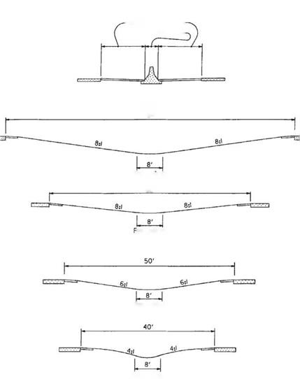
FIGURE 2.27 Typical designs for medians. Conversion: 1 ft = 0.305 m. (From Location and Design Manual, Vol. 1, Roadway Design, Ohio Department of Transportation, with permission) depends on the traffic volume, speed, degree of access, and available right-of-way. On major streets with numerous business drives, a median consisting of an additional lane, striped as a continuous two-way left turn lane, is appropriate. A solid 6-in-high (0.15-m) lane concrete median may be used in low-speed areas (where the design speed is 40 mi/h (64 km/h) or less) and where an all-paved section is desired and a wider median cannot be justified. Barrier medians are normally recommended for urban facilities when the design speed is over 40 mi/h (64 km/h). However, care must be
exercised when barrier medians are used on expressways with unsignalized at-grade intersections because of sight distance limitations and end treatments of the barrier.

U-Turn Median Openings. U-turn median openings may be provided on express­ways, freeways, or interstate highways with nonbarrier medians where space permits and there is a need. U-turns may be needed for proper operation of police and emer­gency vehicles, as well as for equipment engaged in physical maintenance, traffic service, and snow and ice control. U-turn crossings should not be constructed in barrier-type medians. When U-turn median openings are permitted, it is intended they be spaced as close to 3-mi (4.8-km) intervals as possible. Crossings should be located at points approximately 1000 ft (305 m) beyond the end of each interchange speed change lane.

An example of a typical U-turn median opening is shown in Fig. 2.28, which indi­cates geometric features applicable to crossings located in medians of widths ranging from 40 to 84 ft (12 to 26 m). Turning radius should be modified proportionately for medians of varying widths. Tapers should be 200 ft (61 m) in length for all median widths. The profile grade line should normally be an extension of the cross slope of the shoulder paving, rounded at the lowest point.

Grading and Side Slopes

This section is concerned with the design of the slopes, ditches, parallel channels, and interchange grading. It incorporates into the roadside design the concepts of vehicular safety developed through dynamic testing. Designers are urged to consider flat foreslopes and backslopes, wide gentle ditch sections, and elimination of barriers.

Slopes. Several combinations of slopes and ditch sections may be used in the grading of a project. Details and use of these combinations are discussed in subsequent paragraphs. In general, slopes should be made as flat as possible to minimize the necessity for barrier protection and to maximize the opportunity for a driver to recover

TABLE 2.24 Recommended Pavement Widening on Horizontal Curves, ft, for WB-50 Design Vehicles

Degree of curve

Pavement width on tangent, ft

24

22

20

Design speed, mi/h

Design speed, mi/h

Design speed, mi/h

30

to

39

40

to

49

50

to

59

60

to

69

70

and

over

30

to

39

40

to

49

50

to

59

60

and

over

30

to

39

40

to

49

50

to

59

60

and

over

1°00′

0

0

0

0

0

1.0

1.0

1.0

1.0

1.5

2.0

2.0

2.0

2°00′

0

0.5

0.5

0.5

0.5

1.0

1.5

1.5

1.5

2.0

2.5

2.5

2.5

3°00′

0.5

1.0

1.0

1.0

1.0

1.5

2.0

2.0

2.0

2.5

3.0

3.0

3.0

4°00′

1.0

1.0

1.5

1.5

1.5

2.0

2.0

2.5

2.5

3.0

3.0

3.5

3.5

5°00′

1.5

1.5

2.0

2.5

2.5

3.0

3.0

3.0

3.5

3.5

4.0

4.0

6°00′

2.0

2.0

2.5

2.5

3.0

3.0

3.5

3.5

3.5

4.0

4.5

4.5

7°00′

2.0

2.0

3.0

3.0

3.5

4.0

4.0

4.5

5.0

8°00′

2.5

3.0

3.0

3.5

4.0

4.0

4.5

5.0

5.0

9°00′

3.0

3.0

3.5

4.0

4.0

4.5

5.0

5.0

5.5

10°00′

3.0

3.5

4.0

4.5

5.5

5.5

11°00′

3.5

4.0

4.5

5.0

5.5

6.0

12°00′

4.0

4.0

5.0

5.0

6.0

6.0

13°00′

4.0

4.0

5.0

5.0

6.0

6.0

14°00′

4.5

4.5

5.5

5.5

6.5

6.5

14°30′

4.5

5.0

5.5

5.5

6.5

6.5

15°00′

5.0

6.0

7.0

18°00′

5.5

7.0

7.5

19°00′

6.0

7.0

8.0

21°00′

6.5

7.5

8.5

22°00′

6.5

7.5

8.5

25°00′

7.5

8.5

9.5

26°00′

7.5

8.5

8.5

26°30′

8.0

9.0

10.0

Conversions: 1 mi/h = 1.609 km/h, 1 ft = 0.305 m.

Note: Values less than 2.0 ft may be disregarded. Multiply table values by 1.5 for three lanes and by 2.0 for four lanes.

Source: Location and Design Manual, Vol. 1, Roadway Design, Ohio Department of Transportation,

with permission.

control of a vehicle after leaving the traveled way. Regardless of the type of grading used, projects should be examined in an effort to obtain flat slopes at low costs. For example, fill slopes can be flattened with material that might otherwise be wasted, and backslopes can be flattened to reduce borrow.

To better understand the various types of grading, it is necessary to become familiar with the concept of a clear zone. Clear zone is defined as the unobstructed, relatively flat area provided beyond the edge of the traveled way for the recovery of errant vehicles and includes any shoulders or auxiliary lanes (Ref. 1, 2). Chapter 6 discusses the road­side safety aspects of designing for the clear zone, including the use of barriers to shield objects in the clear zone. In the following paragraphs, four types of roadside grading are described. The designer must select the appropriate one for the roadway being designed.

Grading and Side Slopes

Safety grading is the shaping of the roadside using 6:1 or flatter slopes within the clear zone area, and 3:1 or flatter foreslopes and recoverable ditches beyond the clear zone. Safety grading is used on interstate highways, other freeways, and expressways. Figures 2.17 and 2.18 show many of these details.

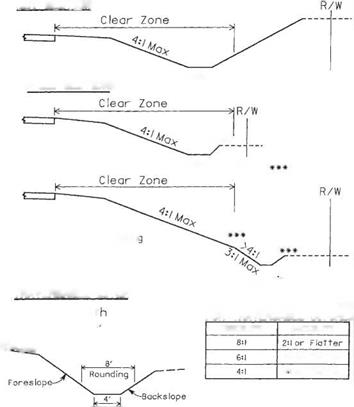
Clear zone grading is the shaping of the roadside using 4:1 or flatter foreslopes and traversable ditches within the clear zone area. Foreslopes of 3:1 may be used but are not measured as part of the clear zone distance. Clear zone grading is recommended

(A)

Grading and Side Slopes

Treated width includes that portion of the shoulder improved with stabilized aggregate or better.

(B) Minimum barrier clearance.

(C) 3’on interstate, other freeways and expressways.

(D) Treated shoulder width may equal graded shoulder width in some cases.

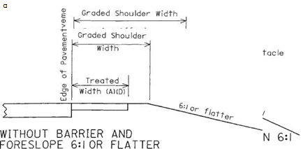
FIGURE 2.13 Cross sections of shoulders showing graded and treated shoulder widths. Conversions: 2 ft = 0.61 m, 3 ft = 0.91 m. (From Location and Design Manual, Vol. 1, Roadway Design, Ohio Department of Transportation, with permission) for undivided rural facilities where the design speed exceeds 50 mi/h (80 km/h), the design hourly volume is 100 or greater, and at least one of the following conditions exists:

• The wider cross section is consistent with present or future planning for the facility.

• The project is new construction or major reconstruction involving significant length.

• The wider cross section can be provided at little or no additional cost.

Grading and Side Slopes

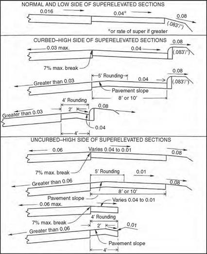
FIGURE 2.14 Recommended cross slopes and grade breaks for paved shoulders. Conversion: 1 ft = 0.305 m. (From Location and Design Manual, Vol. 1, Roadway Design, Ohio Department of Transportation, with permission)

Figure 2.19 shows examples of clear zone grading and traversable ditches.

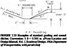
Standard grading is the shaping of the roadside using 3:1 or flatter foreslopes and normal ditches. Standard grading is used on undivided facilities where the conditions for the use of safety grading or clear zone grading do not exist. The designer should ensure that any obstacles within the clear zone receive proper protection. Figure 2.20 shows examples of standard grading and normal ditches.

Grading and Side Slopes

HIGH SIDE OF SUPERELEVATED SECTIONS

Grading and Side Slopes

2′- 6"

Grading and Side Slopes

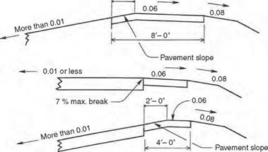
FIGURE 2.15 Recommended cross slopes and grade breaks for bituminous surface treated or stabilized aggregate shoulders. Conversion: 1 ft = 0.305 m. (From Location and Design Manual, Vol. 1, Roadway Design, Ohio Department of Transportation, with permission)

Barrier grading is the shaping of the roadside when a barrier is required for slope protection. Normally, 2:1 foreslopes and normal ditch sections are used. Figure 2.20 includes an example of barrier grading.

Rounding of Slopes. Slopes should be rounded at the break points and at the intersection with the existing ground line to reduce the chance of a vehicle’s becoming airborne and to harmonize with the existing topography. Rounding at various locations is illustrated in Figs. 2.17 to 2.20.

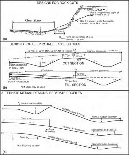
Special Median Grading. Figure 2.21c shows some examples of median grading when separate roadway profiles are used.

Grading and Side Slopes

HIGH SIDE OF SUPERELEVATED SECTIONS

Grading and Side Slopes

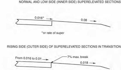
The break at the edge of the pavement shall not exceed 7%.

FIGURE 2.16 Recommended cross slopes and grade brakes for turf shoulders. Conversion: 1 ft = 0.305 m. (From Location and Design Manual, Vol. 1, Roadway Design, Ohio Department of Transportation, with permission)

Rock and Shale Slopes. In rock or shale cuts, the maximum rate of slope should be determined by a soils engineer. In deep rock or shale cuts where slopes are steeper than 1:1, a 10-ft-wide (3.05-m) bench should be provided between the top of the ditch back – slope and the toe of the rock face as illustrated in Fig. 2.21a. In shale cuts, the designer should not use backslopes steeper than 2:1 unless excessive waste would result. In any event, 2:1 slopes should be used for all shale cut sections less than 20 ft (7 m) in depth, and the bench should be omitted. In this discussion, depth of cut is measured from the top of shale or rock to the ditch flow line. Backslopes steeper than 2:1 should not be used in rock cuts until the depth exceeds 16 ft (5 m). In such cases the bench may be omitted.

Curbed Streets. Figure 2.22 shows typical slope treatments next to curbed streets.

Driveways and Crossroads. At driveways or crossroads, where the roadside ditch is within the clear zone distance and where clear zone grading can be obtained, the ditch and pipe should be located as shown on Fig. 2.23.

Подпись: -T2f.TYY , у-* tyj isrsrsrmL = о — •* CO V ◦ CO N Approximate guide for cut depth ” Grading and Side SlopesCUT SECTION

URBAN INTERSTATE, OTHER FREEWAYS AND EXPRESSWAYS

I • 8:1 I

9-6- oitch

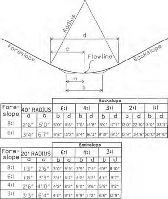
If backslope exceeds 3:1, use 40′ radius as shown above.

Подпись:SHALLOW CUT OR LOW FILL

•*

Recoverable Oitch

Slope transition between low fill design and medium fill design shall be such that the flowline of the roadside ditch does not turn toward the roadway.

Подпись: t 6:1 slope may be usedПодпись:Grading and Side Slopes

Grading and Side Slopes

K – Clear zone – sj

Ml]}

MEDIUM FILL

Application of these sections may vary to avoid frequent slope changes and to maintain reasonably straight ditches.

FIGURE 2.17 Cross sections showing safety grading for four different conditions. Conversion: 1 ft = 0.305 m. (From Location and Design Manual, Vol. 1, Roadway Design, Ohio Department of Transportation, with permission)

Ditches. When the depth or velocity of the design discharge accumulating in a roadside or median ditch exceeds the desirable maximum established for the various highway clas­sifications, a storm sewer will be required to intercept the flow and carry it to a satisfactory outlet. If right-of-way and earthwork considerations are favorable, a deep, parallel side ditch (see Fig. 2.21b) may be more practical and should be considered instead of a storm sewer. In some cases where large areas contribute flow to a highly erodible soil cut, an intercepting ditch may be considered near the top of the cut to intercept the flow from the

Grading and Side Slopes

FIGURE 2.18 Details of ditch rounding for safety grading. Conversions: 1 ft = 0.305 m, 1 in = 0.0254 m. (From Location and Design Manual, Vol. 1, Roadway Design, Ohio Department of Transportation, with permission)

outside and thereby relieve the roadside ditch. Constant-depth ditches (usually 18 in or 0.46 m deep) are desirable. Where used, the minimum pavement profile grades should be 0.24 to 0.48 percent. Where flatter pavement grades are necessary, separate ditch profiles are developed and the ditch flow line elevations shown on each cross section.

Parallel Channels. Where it is determined that a stream intercepted by the roadway improvement is to be relocated parallel to the roadway, the channel should be located beyond the limited access line (or highway easement line) in a separate channel ease­ment. This arrangement locates the channel beyond the right-of-way fence, if one is to be installed. Figure 2.21b shows a parallel channel section. This does not apply to con­ventional intercepting erosion control ditches located at the top of cut slopes in rolling terrain.

In areas of low fill and shallow cut, protection along a channel by a wide bench is usually provided. Fill slope should not exceed 6:1 when this design is used, and maxi­mum height from shoulder edge to bench should generally not exceed 10 ft (3.05 m). If it should become necessary to use slopes steeper than 6:1, guiderail may be necessary

Подпись: Traversable Ditch (See below)
Подпись: **FILL SECTIONS

Grading and Side SlopesCUT SECTION

**■*

Подпись: 4' RoundingTraversable Ditch
(See below)

**For fill heights over!6′ use barrier gradlnc

Normal Ditch

Подпись: Minimum Dept Cut: |.5', Fill: i.O ^toujder Grading and Side Slopes

TRAVERSABLE DITCH

FIGURE 2.19 Examples of clear zone grading and traversable ditches. Conversion: 1 ft = 0.305 m. (From Location and Design Manual, Vol. 1, Roadway Design, Ohio Department of Transportation, with permission)

and fill slopes as steep as 2:1 may be used. In cut sections 5 ft (1.52 m) or more in depth, earth barrier protection can be provided. This design probably affords greater protection where very deep channels are constructed and requires less excavation. Where the sections alternate between cut and fill and it is desired to use but a single design, earth barrier protection is less costly if waste excavation material is available. Likewise, bench protection is less costly if borrow is needed on the project as a whole.

Earth bench or earth barrier protection provided adjacent to parallel channels should not be breached for any reason other than to provide an opening for a natural or relocated stream that requires a drainage structure larger in rise than 42 in (1.07 m). Outlet pipes from median drains or side ditches should discharge directly into the par­allel channel.

Channels and toe-of-slope ditches, used in connection with steep fill slopes, are both removed from the normal roadside section by benches. The designer should establish control offsets to the center of each channel or ditch at appropriate points that govern alignment so the flow will follow the best and most direct course to the outlet. Bench width should be varied as necessary.

STANDARD GRADING

Подпись:

Подпись: 51 or I ess BARRIER GRADING Подпись: Over 5' Grading and Side Slopes
Grading and Side Slopes

FILL

Подпись: Slope all benches to drain ■ (3 to 5% recommended) & * Подпись:Подпись:

Подпись: Norma I Di tch Usually 10' (see below) FILL 41 ROUNDING rvi- ■—. X I'M.n. І2Г
Подпись: NORMAL DITCH SECTIONS CUT

Slope may be flatter than l^^b’V Exceeds 16 if excess material and right – 0r> » ^ of-way are available at little cost. ‘•*/

Interchange Grading. Interchange interiors should be contour-graded so that maximum safety is provided and the least amount of guiderail is required. Figures 2.24 and 2.25 show examples. The generous use of flat slopes (6:1 or flatter) will also be easier for main­tenance crews to work with. Sight distance is critical for passenger vehicles on ramps as they approach entrance or merge areas. Therefore, sight distance should be unobstructed by landscaping, earth mounds, or other barriers on the merging side of the vehicle.

Crossroads. At a road crossing within an interchange area, bridge spill-through slopes should be 2:1, unless otherwise required by structure design. They should be flattened to 3:1 or flatter in each corner cone and maintained at 3:1 or flatter if within the interior of an interchange. Elsewhere in interchange interiors, fill slopes should not exceed 3:1.

Ramps. Roadside design for ramps should be based on Fig. 2.17 or 2.18, depending on the mainline grading concept.

Grading and Side Slopes

FIGURE 2.21 Examples of special designs for grading. (a) Designs for rock cuts. (b) Designs for deep, parallel side ditches. (c) Alternate median designs. Conversion: 1 ft = 0.305 m. (From Location and Design Manual, Vol. 1, Roadway Design, Ohio Department of Transportation, with permission)

Gore Area. Gore areas of trumpets, diamonds, and exteriors of loops adjacent to the exit point should be graded to obtain slopes of 6:1 or flatter, which will not endanger a vehicle unable to negotiate the curvature because of excessive speed.

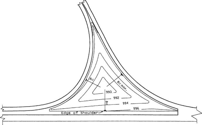
Trumpet Interiors. Interior areas of trumpets (Fig. 2.24) should be graded to slopes not in excess of 8:1, sloping downward from each side of the triangle to a single, rounded low point. Roadside ditches should not be used. Exteriors should be graded in accordance with mainline or ramp standards.

Grading and Side Slopes

To be used on clear zone grading projects where the roadside ditch flowline is located within the clear zone distance

FIGURE 2.23 Slopes and ditches at driveway and crossroad in cut or low fill for use on clear zone grading projects where ditch is within clear zone distance. (From Location and Design Manual, Vol. 1, Roadway Design, Ohio Department of Transportation, with permission)

Подпись: 135Grading and Side Slopes

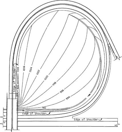
Loop Interiors. In cut, the interior of a loop should be graded to form a normal ditch section adjacent to the lower part of the loop, and the backslope should be extended to intersect the opposite shoulder of the upper part of the loop. This applies unless the character and the amount of material or the adjacent earthwork balances indicate that the cost would be prohibitive. Roadside cleanup and landscaping should be provided in undisturbed areas of loop interiors. If channels are permitted to cross the loop interior, slopes should not be steeper than 4:1. Figure 2.25 shows an example.

Diamond Interiors. If the location of the ramp intersection at the crossroad is relatively near the main facility, a continuous slope between the upper roadway shoulder and the lower roadway ditch will provide the best and most pleasing design. If the ramp

Grading and Side Slopes

FIGURE 2.25 Contour grading of loop interior in cut section at interchange with contour elevations shown in feet. Conversion: 1 ft = 0.305 m. (From Location and Design Manual, Vol. 1, Roadway Design, Ohio Department of Transportation, with permission)

intersection at the crossroad is located a considerable distance from the main facility, then both ramp and mainline roadsides should have independent designs, until the slopes merge near the gore.

If the quadrant is entirely, or nearly so, in cut, the combination of a 3:1 backslope at the low roadway ditch and a gentle slope down from the high roadway shoulder will provide the best design in the wide portion of the quadrant. Approaching the gore, the slopes should transition to continuous 4:1 and 6:1 or flatter slopes. Quadrants located entirely in fill areas should have independently designed roadways for ramp, mainline, and crossroad. Each should be provided with normal slopes not greater than 3:1, with the otherwise ungraded areas sloped to drain without using ditches. If the quadrant is located part in cut and part in fill, the best design features a gentle fill slope at the upper roadway and a gentle backslope at the lower roadway, joined to a bench at the existing ground level that is sloped to drain. The combination of a long diamond ramp having gentle alignment with a loop ramp in the same interchange quadrant is not to be treated as a trumpet. Each ramp should be designed independently of the other in accordance with the suggested details set forth above.

2.3.1 Bridge Criteria

Although bridge engineering is discussed in Chap. 4, information on pertinent physical dimensions is presented here. Lateral clearance at underpasses and vertical clearance over roadways, as used in Ohio, are given in Table 2.25 for new and reconstructed bridges. The table notes provide a good insight into when variations from the standards are allowed.

Roadway Criteria

Lane Widths and Transitions. When considering the physical characteristics of cross sections, the values selected will depend on location (rural or urban), speed, traffic volumes, functional classification, and, in urban areas, the type of adjacent development. Tables 2.21, 2.22, and 2.23 provide values currently used in Ohio. Lane width is dependent on design speed, especially in rural areas. Widths may be as narrow as 9 ft (2.74 m) for a local, low-volume road. In urban areas, lane widths can be as narrow as 10 ft (3.05 m), if the road is primarily a residential street. The maximum lane width is generally accepted to be 12 ft (3.66 m) in all locales.

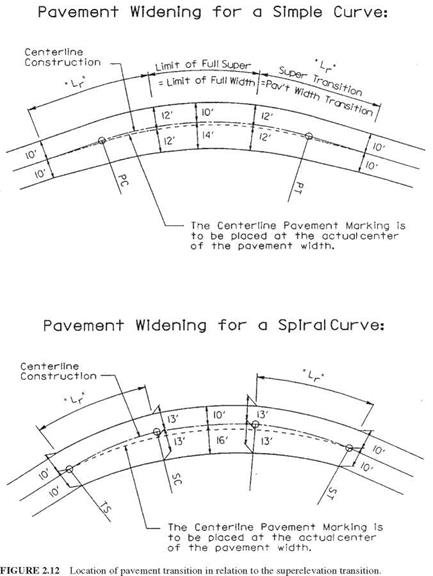
In some cases it may be necessary to widen the pavement on sharp curves to accommodate off-tracking of larger vehicles. Table 2.24 provides a chart of recom­mended pavement widening based on degree of curvature and design speed. These values are based on a WB-50 design vehicle. The widened portion of the pavement is normally placed on the inside of the curve. Where curves are introduced with spiral transitions, the widening occurs over the length of the spiral. On alignments without spirals, the widening is developed over the same distance that the superelevation tran­sition occurs. The centerline pavement marking and the center joint (if applicable) should be placed equidistant from the pavement edges. See Fig. 2.12 for illustrations of curve widening.

Whenever the driver’s lane is being shifted—for example, when lanes are being added or eliminated—the shifting rate should be controlled using the following equations:

L = WS for design speeds over 40 mi/h (2.5)

S 2

L = W for design speeds up to 40 mi/h (2.6)

where L = approach taper length, ft W = offset width, ft S = design speed, mi/h

Where lanes are being added but the driver is not being “forced” to follow the actual transition (such as in adding right turn lanes), the transition can occur in 50 ft (15 m) on most roadways or 100 ft (30 m) on freeway designs.

Pavement Cross Slopes. Roadways on tangent or relatively straight alignments where no superelevation is required are normally crowned (peaked) in the middle. Cross slopes are usually in the range of 0.015 to 0.020 ft/ft (m/m). Urban areas with curbed pavements are more likely to have a slope near the upper limit, while rural roadways tend to have a little flatter cross slope. The following guidelines are applica­ble to the location of the crown point:

• Crowns should be located at or near lane lines.

• For pavements with three or four lanes, no more than two should slope in the same direction.

• Undivided pavement sections should be crowned in the middle when the number of lanes is even, and at the edge of the center lane when the number is odd.

• Narrow raised median sections should be crowned in the middle, so that the majority of the pavement will drain to the outside.

TABLE 2.21 Guide for Selecting Lane Width for Rural Areas(A)

Minimum lane widths, ft,[2] for design speed, mi/h

Functional

classification

Design year ADT

20

25

30

35

40

45

50

55

60

65

70 or >

Interstate, other

ALL

12

12

12

12

12

freeways and expressways Arterial

> 4000

12

12

12

12

12

12

12

2001-4000

12

12

12

12

12

12

12

1001-2000

11

11

12

12

12

12

12

400-1000

11

11

12

12

12

12

12

< 400

11

11

12

12

12

12

12

Collector

> 4000

12

12

12

12

12

12

(C)

12

(C)

12

12

2001-4000

12

12

12

12

12

12

12

12

12

1001-2000

11

11

11

11

11

11

11

12

12

400-1000

10

10

10

11

11

11

11

11

11

< 400

10

10

10

10

10

10

10

11

11

Local

> 4000

12

12

12

12

12

12

12

12

12

2001-4000

12

12

12

12

12

12

12

12

12

1001-2000

(D)

10

(D)

11

(D)

11

(D)

11

(D)

11

(D)

11

11

12

12

400-1000

10

10

10

10

11

11

11

11

11

< 400

9

9

9

9

9

10

10

11

11

Conversions: 1 mi/h = 1.609 km/h, 1 ft = 0.305 m. Notes:

(A) There may be some rural locations that are urban in character. An example would be a village where adjacent development and other conditions resemble an urban area. In such cases, urban design criteria may be used.

(B) The number of lanes should be determined by a capacity analysis.

(C) May be 11 ft on nonfederal projects if design year ADT includes less than 25 (B) and (C) truck units.

(D) An 11-ft lane width may be retained on reconstructed highways if the alignment and safety records are satisfactory.

Source: Location and Design Manual, Vol. 1, Roadway Design, Ohio Department of Transportation, with

permission.

Shoulders. A shoulder is the area adjacent to the roadway that (1) when properly designed, can provide lateral support to the pavement, (2) is available to the motorist in emergency situations, and (3) can be used to maintain traffic during construction. Graded shoulder width is the width of the shoulder measured from the edge of the pavement to the intersection of the shoulder slope and the foreslope. Treated shoulder width is that portion of the graded shoulder that has been improved to at least stabilized aggregate or better. Figure 2.13 illustrates these definitions.

Four basic types of shoulders are used: (1) paved, (2) bituminous surface treated,

(3) stabilized aggregate, and (4) turf. Paved shoulders may be rigid (concrete) or flexible (asphalt). Turf shoulders are usually used on low-volume, uncurbed, local roads. Tables 2.22 and 2.23 provide recommended shoulder widths and types based on functional classification and traffic volumes or locale.

TABLE 2.22 Guide for Selecting Shoulders for Rural Areas’*1


Graded width, ft Rounding, ft (B)


Functional

Design year ADT

With barrier or foreslope steeper than 6:1

Without barrier 6:1 or flatter

Treated

for design speed, mi/h

Guardrail offset, ft (from traveled way) (D)

classification

foreslope

width, ft

Type(C)

> 50

< 50

Interstate, Other Freeways & Expressways

All

17′ Rt.

9′ Med. (E)

12′ Rt.

4′ Med. (F)

12′ Rt. (G) 4′ Med. (F)

Paved

10′

(H)

Arterial (K)

>4000

14′

10′

10′

PVD (I)

8′

4′

12′

2001U000

12′

8′

8′

PVD (I)

8′

4′

10′

1001-2000

10′

8′

6′

BIT. SRF. TRT.(L)

8′

4′

8′

400-1000

10′

8′

6′

BIT. SRF. TRT.(L)

4′

4′

8′

<400

8′

8′

4′

STBL. AGG.

4′

4′

6′

Collector (K)

>4000

12′

8′

8′(M)

BIT. SRF. TRT. (L)

8′

4′

10′(N)

2001-4000

10′

8′

4′

BIT. SRF. TRT. (L)

8′

4′

8′(N)

1001-2000

8′

640)

4′

STBL. AGG.

8′

4′

6′(N)

400-1000

6′

4′

4′

STBL. AGG.

4′

4′

4′

<400

6′

(P)

(P)

STBL. AGG

4′

4′

4′

Local

>4000

12′

8′ (Q)

8′(M)

BIT. SRF. TRT.(L)

8′

4′

10′(N)

2001-4000

10′

8′ (Q)

4′

BIT. SRF. TRT. (L)

8′

4′

8′(N)

1001-2000

8′

640)

4′

STBL. AGG

8′

4′

6′(N)

400-1000

6′

4′

4′

STBL. AGG.

4′

4′

4′

<400

6′

(P)

(P)

STBL. AGG.

4′

4′

4′


Подпись: 120

(E) If 6 or more lanes, use 17 ft. If the truck traffic is less than 250 DDHV use 15 ft.

(F) If 6 or more lanes, use 12 ft. If truck traffic is less than 250 DDHV, 10 ft treated width may be used.

(G) Use 10 ft if truck traffic is less than 250 DDHV. If 10 ft treated width is used, graded width may be reduced by 2 ft.

(H) Guardrail offset is treated width plus 2 ft.

(I) A fully paved shoulder is preferred, but may not be economically feasible. Therefore, a minimum 2 ft of the treated shoulder should be paved. The remainder of the treated shoulder may be either stabilized aggregate or bituminous surface-treat­ed material according to the criteria stipulated in Notes (K) and (L).

(J) Use bituminous surface treated if design year ADT includes between 250 and 1000 (B) and (C) truck units.

(K) The median shoulder width criteria for interstates, other freeways and expressways shall apply to the medians of divided arterials and divided collectors.

(L) Stabilized aggregate may be used on state-maintained roads if the design year ADT includes less than 250 (B) and (C) truck units. Paved shoulders are recommended if the design year ADT includes over 1000 (B) and (C) truck units.

(M) Use 6 ft if design year ADT includes less than 501 (B) and (C) truck units. If 6 ft treated width is used, graded width may be reduced to 10 ft and minimum barrier offset will be 8 ft.

(N) Whenever a design exception is approved for graded shoulder width, the guardrail offset may be reduced but shall not be less than 4 ft.

(O) A 6-ft turf shoulder may be used with a 4:1 or flatter foreslope.

(P) See AASHTO’S Guidelines for Geometric Design for Very Low-Volume Local Roads for values.

(Q) An 8-ft graded shoulder may be used with a 4:1 or flatter foreslope.

Source: Location and Design Manual, Vol. 1, Roadway Design, Ohio Department of Transportation, with permission.

TABLE 2.23 Guide for Selecting Lane Width and Shoulders for Urban Areasa

Functional

classification

Locale

Lane width, ft Minimum Preferred

Minimum curbed shoulder width,’b ft

Without With parking lane parking lanec

Interstates, other freeways, and expressways

All

12

12

12 right paved,

4 median paved de

Arterial streets

50 mi/h or more

12

12

10 each side paved

Less than 50 mi/h

12h

12

1-2 paved

10-12 paved

Collector streets

Commercial or industrial

11

12

1-2 paved

9-10 paved

Residential

11

12

1-2 paved

7-10 paved

Local streets

Commercial or industrial

11

12

1-2 paved

9 paved

Residential

10′

11

1-2 paved

7 paved

Conversions: 1 mi/h = 1.609 km/h, 1 ft = 0.305 m.

aUse rural criteria (Tables 2.21 and 2.22) for uncurbed shoulders. Rural functional classification should be determined after checking the urban route extension into a rural area.

‘See Sections 305.3.2 and 305.3.3 for use of curbs and notes on curb/guardrail relationships.

cUse minimum lane width if, in the foreseeable future, the parking lane will be used for through traffic during peak hours or continuously.

dUse 10 ft median shoulder on facilities with 6 or more lanes. Use 12 ft median shoulder on facilities with 6 or more lanes and when truck traffic exceeds 250 DDHV.

eMay be reduced to 10 ft if the truck traffic is less than 250 DDHV.

fMay be reduced to 8 ft if DHV is less than 250.

gThe median shoulder width for divided arterials shall follow the median criteria for Interstates, other Freeways and Expressways.

hLane width may be reduced to 11 ft where right-of-way is limited and current truck ADT is less than 250; however, on all Federal Aid Primary (FAP) roadways at least one 12-ft lane in each direction is required. FAP listings may be obtained from Office of Technical Services’s Roadway Inventory reports.

‘Lane width may be 9 ft where right-of-way is limited and current ADT is less than 250.

Source: Location and Design Manual, Vol. 1, Roadway Design, Ohio Department of Transportation, with permission.

Whenever practical, shoulders should be designed to be wide enough and strong enough to accommodate temporary traffic, especially on high-volume roadways. Figures 2.14, 2.15, and 2.16 provide information on recommended cross slopes [ft/ft (m/m)] and allowable grade breaks depending on the type of shoulder chosen.

The Soil Water Characteristic Curve (SWCC)

The soil water characteristic curve (SWCC) provides the relationship between the matric suction and water content for a given soil. In fact, calling the curve “character­istic” is something of a misnomer as the relationship is not solely a function of the soil type, but varies with (for example) temperature, pressure and pore water chemistry. A typical soil water characteristic curve for sand and clay can be seen in Fig. 2.9a.

Подпись: Capillary pressure Подпись: Capillary pressure Moisture content, 0 [% by vol]

Figure 2.9 shows clearly that, even at very high matric suctions (capillary pres­sures), all the water cannot be removed from the soil. The residual (or the irre­ducible) water content, usually denoted 0r (and in a similar way the irreducible water saturation, Srr) is the water content that is not removed in the soil even when a large amount of suction is applied.

Fig. 2.9 (a) Typical characteristic curves for coarse grained (gravel, sand) and fine grained soils (clay, silt). (b) Soil water characteristic curve showing drainage, wetting and scanning (intermedi­ate) curves. The dotted line represents the irreducible (residual) water content

1.5.1 Hysteresis Behaviour

For most soils the soil water characteristic curve (SWCC) shows hysteresis. This means that the 5 – в (or the Ф – 0) relationship depends on the saturation history
as well as on the existing water content. Figure 2.9b shows the SWCC for drainage and wetting conditions. The upper curve corresponds to a soil sample that is initially saturated and is drained by increasing the matric suction (capillary pressure), hence the drainage curve. The lower curve is called the wetting curve and gives the re­wetting of the soils with corresponding decrease in capillary pressure. If a wetting or a drainage process is stopped between the two endpoints and a reverse process is starting the scanning curves (indicated by arrows) are followed.

Determine the sill’s position

Depending on what you find after measuring the foundation, you may need to adjust the sill’s position using some of the techniques explained in the sidebar on p. 55. The sill plates are often bolted flush to the outside of the foundation, but there are variations you may want to consider (see the illustration on p. 58). For example, when the walls will be sheathed with ‘/i-in. plywood or OSB, it’s best to hold the plates Vi in. inside the founda­tion. This puts the sheathing flush with the foundation and allows the siding to lap down over the concrete.

The sills must be installed along snapped layout lines on top of the foundation walls. (If

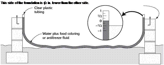
Подпись: This side of the foundation is 1/2 in. lower than the other side.

USING A WATER LEVEL

A simple water level can be used to check the foundation for level. These are available at home improvement centers. If the foundation is not level, the sill plate can be shimmed up with pressure-treated shims.

Determine the sill’s position

you’re building on a slab, the layout lines will be on top of the slab.) The lines identify where the inside edge of the sill will fit.

Taking the width of the sill lumber into account (31/2 in. for a 2×4 sill, 51/2 in. for a 2×6), snap chalklines around the perimeter to indicate the inside edge of the sill (see the photo on p. 56). Make slight adjustments in the positions of the chalklines, if necessary, so that the sill is straight, square, and parallel.

Choosing a foundation

Each foundation system has many variations, and it is important to select the one best suited to the climate, the soil type, the site, and the building program. With all foundations, you should investigate the local soil type. Soil types, along with their bearing capacities, are often described in local soil profiles based on informa­tion from the U. S. Geological Survey (USGS). If there is any question about matching a foundation system to the soil or to the topography of the site, consult a soil or structural engineer before construction begins. This small investment may save thousands of dollars in future repair bills.

design checklist

Because the foundation is so important to the longevity of the building and because it is so difficult to repair, it is wise to be conservative in its design and construc­tion. Make the foundation a little stronger than you think you need to. As a minimum, even if not required by code, it is recommended that you follow this rule-of – thumb checklist:

1. Place the bottom of the footing below the frost line on solid, undisturbed soil that is free of organic mate­rial. (Local codes will prescribe frost-line depth.)

2. Use continuous horizontal rebar in the footing and at the top of foundation walls (joint reinforcing may be allowable in concrete-block walls). Tie the footing and wall together with vertical rebar.

3. Tie wood members to the foundation with bolts or straps embedded in the foundation. Anchoring require­ments in hurricane and severe earthquake zones are shown in the following chapters, but specific require­ments should be verified with local codes.

4. Provide adequate drainage around the foundation. Slope backfill away from the building and keep soil

6 in. below all wood.

Many codes and many site conditions require mea­sures beyond these minimum specifications. In addi­tion, there are several other considerations important
to a permanent foundation system, and these are dis­cussed in this chapter. They include support of loads that do not fall at the perimeter wall, such as footings for point loads within the structure and at porches and decks; insulation and moisture barriers; waterproofing and drainage; protection against termites, other insects and wood-decaying organisms; and precautions against radon gas.

5. Get the details right. Use pressure-treated or other decay-resistant wood in contact with concrete. Straps, hangers, and fasteners in contact with pres­sure-treated lumber should be hot-dip galvanized to protect against degradation from the preservative chemicals. Use a moisture barrier between all con­crete and untreated wood.

other foundation systems

The permanent wood foundation (PWF), developed in the 1970s, now accounts for about 5% of founda­tions in the United States and 20% in Canada. Made of pressure-treated framing, the crawl-space or base­ment walls sit on a bed of compacted gravel rather than a concrete footing. The same framing crew that constructs the structure above can build the founda­tion walls; and when insulation, wiring, and other utili­ties are required, they can be located in wall cavities between studs as they are in the rest of the building.

Insulating concrete formwork (ICF) may be used in place of wooden formwork for the walls of a basement or heated crawl space. The insulation stays in place after the concrete walls have been poured and provides thermal separation for the space within. ICF walls must be protected on the exterior, and wiring and other utili­ties must be either integrated or carved into the inte­rior insulation surface.