Filter Design

Pavement structures consist of material layers with different grain size gradations and different mechanical as well as permeability properties. As water will flow through the structure it is important that migration of a portion of the fines from one layer to the next will not take place. To achieve this, the principles of fil – tration/separation must be applied at each interface (Cedergren, 1977). This is of special interest where water flows from fine grained material into a coarser grained material on its way out of the structure.

In applying the filter criteria the material to be drained is frequently referred to as the base material and the new material to be placed against it the filter material. The filter criteria stipulate that the filter needs to fulfil two functions:

• water needs to drain freely through it (filtration function or permeability criteria); and

• only a limited quantity of solid particles are allowed to move from the base layer into or through the filter layer (separation function or piping requirement). This criteria is set as otherwise the coarse grained material could be filled or clogged with time.

These two functions are in conflict with each other as filtration requires a high discharge through the filter while separation requires this to be small. The conditions of these two requirements can be expresses as:

Подпись: (2.25)—f —f

—5 > 4 to 5 & —5 < 4 to 5

D?5 — Ї5

where —15 is the diameter in the particle-size distribution curve for the filter material corresponding to 15% finer and — b5 and — b5 are the diameter in the particle-size distribution curve for the base material corresponding to 15% and 85% finer respec­tively. The application of these issues is presented in Chapter 13, Section 13.3.9.

STEP 3 BACKFILL AROUND THE FOUNDATION

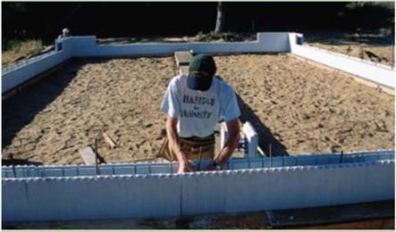
Подпись: BUILDING WALLS WITH INSULATED CONCRETE FORMS Insulated concrete forms (known as ICFs) offer builders an easy way to build insulated concrete walls for crawl-space and basement foundations. Made from polystyrene or another rigid foam, these forms are designed to stay in place; they aren't stripped off like standard forms. It doesn't take a lot of building skill to stack these blocks prop-erly. On a recent job in Oregon, we snapped chalklines on the concrete footing to mark where the first course of form blocks would fit. We then started from the corners and laid two courses of blocks to form the crawl-space walls. With four of us working, it took less than two hours to lay the blocks. Polystyrene blocks interlock, so very little extra bracing is need-ed to hold them in place as concrete is poured into them. A horizon-tal 2x4 screwed to the outside or inside of the wall helps hold the forms straight. Drive a stake in the ground every 4 ft. or so, and run a brace between the stake and the horizontal 2x4.This will keep the walls straight throughout the pour.To strengthen the wall and pre-vent the forms from floating up and away, tie together a network of horizontal and vertical rebar, as shown in the photo below. There are some concerns with ICF walls.The foam can offer a hidden pathway for subterranean termites.To avoid this, install a metal termite shield under the sill plate. Also, the foam surface is rather soft and can be easily dented and gouged.To prevent this, cover the outside walls with 2-ft. by 8-ft. fiber-cement panels or stucco. STEP 3 BACKFILL AROUND THE FOUNDATION

The foundation is ready for the floor framing work to begin. But the job site isn’t. Backfilling against the walls restores at least some of the site’s original contour, making it safer and easier to move around. If you’re building a house with a full basement, the backfilling process is usu­ally delayed until after the first floor is framed and sheathed. Because they are taller, basement walls need the extra rigidity provided by the floor framing to ensure that backfilling doesn’t damage the foundation. This isn’t a major concern with crawl-space walls, so it’s good to backfill now. But first, it’s important to take care of the following details.

Termite protection

In areas where termite infestation is possible, some builders elect to call in a licensed pest – control contractor to apply pesticide around the base of the foundation before backfilling against the walls. However, if you don’t like the idea of putting chemicals in the soil, there are other ter­mite control options to consider (see the sidebar on p. 60).

Foundation coatings

It’s important to keep moisture out of the basement or crawl-space area, as well as out of the masonry wall itself. Foundation coatings help accomplish this. Concrete block walls are often parged—covered with a layer of mortar that conceals and protects the joints between the blocks. A waterproof coating should also be applied. Asphalt-type coatings are popu­lar because they are inexpensive and have been used for many years. More effective and more expensive coatings are also available and should be considered when you’re building in soil that stays wet for extended periods of time. No matter how good a waterproof coating is supposed to be, it shouldn’t be your only line of defense against under-house moisture (see the sidebar at left).

Finland

The requirements for cellulose fibers according to PANK 2000 have been divided into obligatory and recommended ones as follows:

• Obligatory requirements

• Water content according to PANK 3103: < 8.0% (m/m),

• Instantaneous heat resistance (mass loss) according to PANK 3104: < 7.0% (m/m)

• Recommended values for bulk fibers

• Bulk density according to PANK 3105: 20-35 g/dm3

• Homogeneity according to PANK 3107: 2.0-2.8%

• Fibers’ length distribution:

– 80% value: 1.2-1.9 mm

– 50% value: 0.5-0.9 mm

• Specific surface area according to PANK 2401: 2.0-3.0 m2/g

Coordination of Horizontal and Vertical Alignments

When designing new roadway projects, the following items should be considered to

coordinate the horizontal and vertical alignments:

• Curvature and tangent sections should be properly balanced. Normally, horizontal curves will be longer than vertical curves.

• It is generally more pleasing to the driver when vertical curvature can be superimposed on horizontal curvature. In other words, the PIs (points of intersection) of both the vertical and horizontal curves should be near the same station or location.

• Sharp horizontal curves should not be introduced at or near the top of a pro­nounced crest vertical curve or at or near the low point of a pronounced sag vertical

curve.

TABLE 2.19 Stopping Sight Distance for Sag Vertical Curves at Design Speeds from 20 to 70 mi/h (32 to 113 km/h)

Подпись: Design speed, mi/h Design SSD, ft Design K, ft/% 20 115 17 21 120 18 22 130 20 23 140 22 24 145 24 25 155 26 26 165 28 27 170 29 28 180 32 29 190 34 30 200 37 31 210 39 32 220 42 33 230 44 34 240 47 35 250 49 36 260 52 37 270 55 38 280 57 39 290 60 40 305 64 41 315 66 42 325 69 43 340 73 44 350 76 45 360 79 Подпись: Design speed, mi/h Design SSD, ft Design K, ft/% 46 375 83 47 385 85 48 400 89 49 415 93 50 425 96 51 440 100 52 455 104 53 465 107 54 480 111 55 495 115 56 510 119 57 525 123 58 540 128 59 555 132 60 570 136 61 585 140 62 600 144 63 615 148 64 630 153 65 645 157 66 665 162 67 680 167 68 695 171 69 715 176 70 730 181

Подпись: For S < L: S

Подпись: Using S = stopping sight distance, ft L = length of sag vertical curve, ft A = algebraic difference in grades, %, absolute value K = rate of vertical curvature, ft per % change • For a given design speed and A value, the calculated length L = KA • To determine S with a given L and A, use the following:
Подпись: 3.5L + V12.25L2 + 160052 2A
Подпись: For S > L: S = (AL + 400)/(2A - 3.5)
Подпись: Conversions: 1 mi/h = 1.609 km/h, 1 ft = 0.305 m. Note: When the algebraic difference A is 1.75 percent or less, SSD is not restricted by the vertical curve. Source: Location and Design Manual, Vol. 1, Roadway Design, Ohio Department of Transportation, with permission.

Height of headlight = 2.00 ft Upward light beam divergence = 1°00′

• On two-lane roadways, long tangent sections (horizontal and vertical) are desirable to provide adequate passing sections.

• Horizontal and vertical curves should be as flat as possible at intersections.

• On divided highways, the use of variable median widths and separate horizontal and vertical alignments should be considered.

• In urban areas, horizontal and vertical alignments should be designed to minimize nuisance factors. These might include directional adjustment to increase buffer zones and depressed roadways to decrease noise.

• Horizontal and vertical alignments may often be adjusted to enhance views of scenic areas.

United States

The United States is one of the few countries where requirements for cellulose fibers and mineral stabilizing agents have been standardized. Some other countries have adopted the U. S. requirements in their own specifications.

The requirements for cellulose and mineral fiber SMA stabilizers after AASHTO MP-8-05 include the following: [22]

• Shot (nonfibrous material) content

• Passing 0.25-mm sieve: 90% ± 5%

• Passing 0.063-mm sieve: 70% ± 10%

• Ash content of cellulose fibers: 18% ± 5% nonvolatiles

• pH of cellulose fibers: 7.5 ± 1.0

• Oil absorption of cellulose fibers: 5.0 ± 1.0 times fiber mass

• Moisture content of cellulose fibers: maximum 5% (m/m)

A Tricky Victorian

This two-family Victorian house (circa 1860) was difficult to upgrade because we weren’t allowed to remove siding, replace the win­dows, or dig into the slate roof.

The historic commission did, however, allow us to remove and replace the siding and windows on one wall where the siding was damaged and needed replacement, so we injected open-cell foam, added house – wrap and furring strips, and replaced the siding on that wall.

Historic commissions all over the country favor historical authenticity over durability and energy efficiency with regard


Tar-paper baffle connects wall and roof insulation.


Kneewall


Drywall is a code-required fire block.


3/4-in. furring strips

Wood

siding


Open-cell spray foam (R-40 in the rafters; – R-14 in the walls)


Housewrap


Подпись: A DRY BASEMENT TO BEGiN WiTH This house had no standing water in the basement, nor was there evidence of previous flooding. Because the basement had historically been dry, we didn't install a perimeter drain and sump pump. Rather, we installed a drainage mat on top of the existing slab (to trap errant seepage) and placed 2 in. of rigid- foam insulation on top of that. We then topped the assembly with a new slab to make a warm, dry storage area. Подпись: ВПодпись:How Much Insulation Do You Need?

ecause the earth is such a great buffer to heat loss and gain, the insulation needs in a house grow as you get farther from the ground. Naturally, they’re greatest at the roof, which is baked by the sun all day and chilled by the sky at night.

We specify significantly higher levels of insulation than are required by the International Energy Conservation Code, and we think it is money well spent. When you’re attempting to approach net-zero energy use in homes, energy that isn’t used is always the cheapest energy.

R-10 under the Basement Slab

It is easy to add 2 in. or 3 in. of extruded (or expanded) polysty­rene under a new slab before pouring the concrete. This could cut into headroom a bit, but the benefits outweigh the cost.

R-20 Basement Walls

Warming basement walls is often the best protection you can get from mold growth. Additional living space is an added ben­efit. Energy codes in most cold climates call for at least R-10, but if you can afford the additional insulation at this time, it is well worth it. Both closed-cell spray foam and rigid-foam insula­tion are good choices.

R-40 in the Walls

By warming above-grade walls, you eliminate chilly convection currents inside a room, which can increase your actual living space because furniture no longer needs to be moved away from exterior walls. While the building code asks for at least R-19 in most cold climates, it is worthwhile to use as much insulation as you can afford.

R-60 in the Roof

Adding insulation to the roof (rather than the attic floor) brings extra living and storage space into the home at little cost. It also reduces summer cooling loads. It’s often easy to provide more than the code minimums because of deep rafter cavities. If you’re reroofing the house, consider putting rigid-foam board insulation on top of the sheathing as we did in two of the case studies here. After judging the performance of the first two houses, we increased our recommendation from R-40 to R-60.

n— 1 ■

П.

■1

wm

1

І

ji

і

в


»

– ~


A Tricky Victorian

A Tricky Victorian

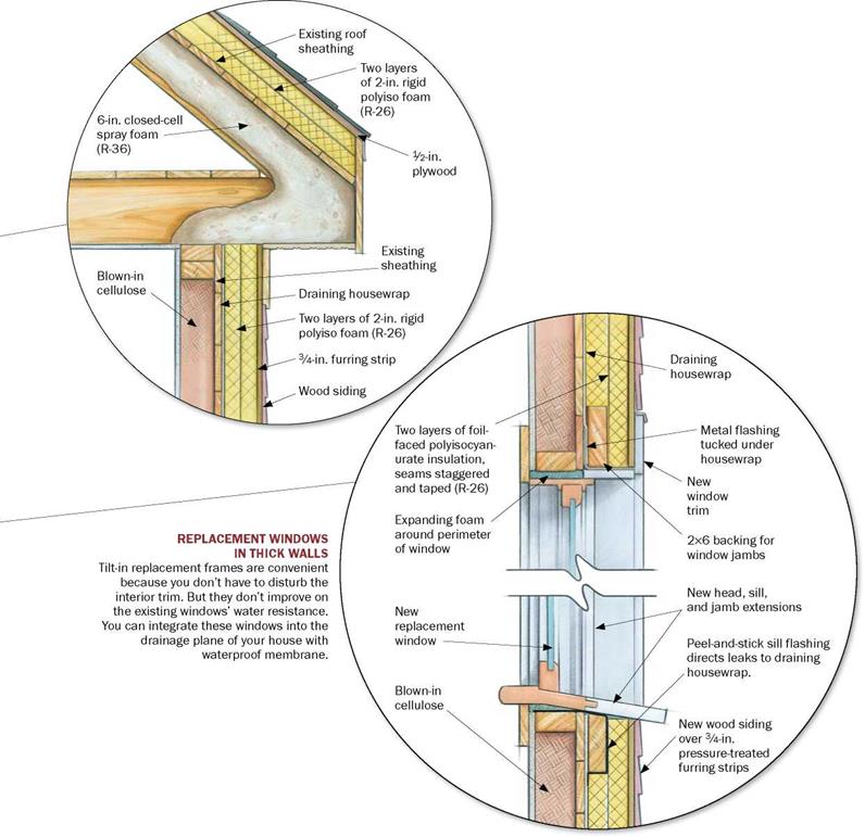
Подпись: iNSULATE OVER AND UNDER THE ROOF DECK To get the most insulation into the shallow 7-in. rafters, we used closed-cell foam. On top of the roof, we added 4 in. of polyisocyanurate foam board, which has the highest R-value per inch of the rigid- foam boards. This yielded an R-60 roof without reframing. We didn't want to disrupt the interior plaster to spray foam into the wall cavities, so we filled the walls with cellulose and covered them with rigid foam.

Third Time Is a Charm

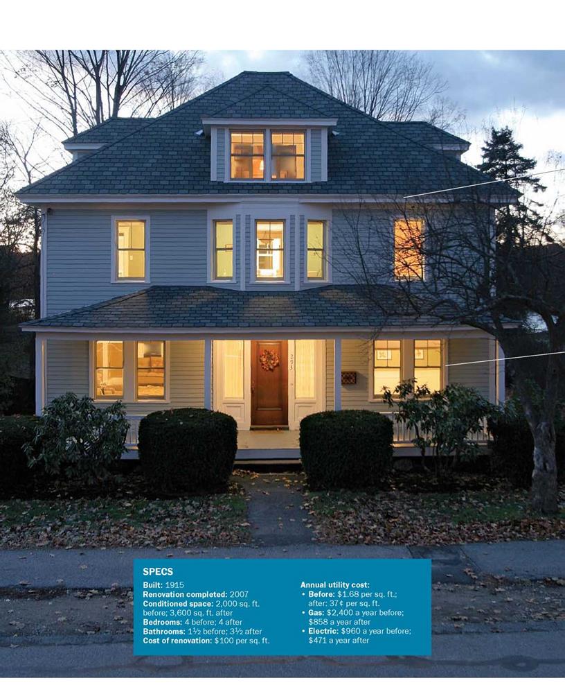
This 1915 foursquare is an American classic found in almost every town in the country. Interior plaster was in great shape, the lay­out was excellent, and there was no struc­tural damage to speak of. Other than adding a few new windows to the back (for better views to a pond) and updating the kitchen, we didn’t disrupt the interior too much. By insulating the basement and roof, we almost doubled the living space of this house with­out adding an inch to the footprint. And the utility bills were cut by 60%.

Better windows would be the next place to reduce energy loads in this house. A triple-glazed unit with heat-mirror technol­ogy might further reduce the heating load, allowing us to get closer to zero.

Betsy Pettit, FAIA, is an architect and a principal of Building Science Corp., now located in the Victorian house featured here.

Requirements for stabilizers

Specifying the desired properties of stabilizers is a troublesome task, which is why there are not very many examples of formalized requirements for them. In fact, detailed testing of a stabilizer’s properties is practically impossible in the asphalt plant laboratory. Therefore, in many countries, testing is limited to draindown check­ing (i. e., only an empirical assessment of stabilizer effectiveness).

A few examples of standardized regulations come from Germany and the United States. Some requirements were also in the Finnish specification PANK 2000.

5.3.1 Germany

The requirements adopted in Germany were cited in a 1997 document entitled

Testing and Marking Stabilizing Additives and Materials Applied for Bituminous

TABLE 5.7

POLAND

SLOVAKIA

GERMANY

SWEDEN

PN-EN 14023:2009/

Katalogove Listy

TL-Bitumen 07

VV Publ 2008:113

AC2010

Asfaltov KLA 1/2009

Properties

Test Method

25/55-55

40/100-75

45/80-55

45/80-55

Penetration at 25°C, 0.1 mm

EN 1426

25-55

40-100

45-80

45-80

Softening point, °С

EN 1427

>55

>75

>55

>55

Force ductility (low speed traction), J/cm2

EN 13589 EN 13703

>3 at 5°C

TBR

>3 at 5°C

>2 at 5°C

Change of mass, %

EN 12607-1

<0.5

<0.5

<0.5

<0.5

Retained penetration after RTFOT, %

EN 1426

>60

>60

>60

>60

Increase in softening point after RTFOT, °С

EN 1427

<8

<10

<8

<12

Flash point, °С

EN ISO 2592

>235

>220

>235

>250

Fraass breaking point, °С

EN 12593

<-10

<-12

<-12

<-18

Elastic recovery at 25°C, %

EN 13398

>50

>50

>50

Elastic recovery at 10°C, %

EN 13398

>75

Plasticity range, °С

p. 5.1.9

TBR

TBR

Storage stability

EN 13399

<5

<5

<5

<5

Difference in softening point, °С

EN 1427


Подпись: Stone Matrix Asphalt: Theory and Practice

Storage stability

Difference in penetration, 0.1 mm Drop in softening point after RTFOT, °С Elastic recovery at 25°C after RTFOT, %

Elastic recovery at 10°C after RTFOT, %

Note: TBR = To Be Reported.

TABLE 5.7

POLAND

SLOVAKIA

GERMANY

SWEDEN

PN-EN 14023:2009/

Katalogove Listy

TL-Bitumen 07

VV Publ 2008:113

AC2010

Asfaltov KLA 1/2009

Properties

Test Method

25/55-55

40/100-75

45/80-55

45/80-55

Penetration at 25°C, 0.1 mm

EN 1426

25-55

40-100

45-80

45-80

Softening point, °С

EN 1427

>55

>75

>55

>55

Force ductility (low speed traction), J/cm2

EN 13589 EN 13703

>3 at 5°C

TBR

>3 at 5°C

>2 at 5°C

Change of mass, %

EN 12607-1

<0.5

<0.5

<0.5

<0.5

Retained penetration after RTFOT, %

EN 1426

>60

>60

>60

>60

Increase in softening point after RTFOT, °С

EN 1427

<8

<10

<8

<12

Flash point, °С

EN ISO 2592

>235

>220

>235

>250

Fraass breaking point, °С

EN 12593

<-10

<-12

<-12

<-18

Elastic recovery at 25°C, %

EN 13398

>50

>50

>50

Elastic recovery at 10°C, %

EN 13398

>75

Plasticity range, °С

p. 5.1.9

TBR

TBR

Storage stability

EN 13399

<5

<5

<5

<5

Difference in softening point, °С

EN 1427


Подпись: Stone Matrix Asphalt: Theory and Practice

EN 13399

EN 1426

EN 12607-1, EN 1427

<2

EN 12607-1, EN 13398

>50

Подпись: Requirements for SMA Materials

TBR

<5


TBR

>50


>50


vo


Surfaces (FGSV Arbeitpapier 42). It contains requirements for all kinds of stabiliz­ers used in aggregate mixtures with a high content of binder, which includes the following:

• Organic fibers

• Mineral fibers

• Powders and dusts

• Compounds of filler and all sorts of fibers

• Special fillers.

The range of testing depends on the type of stabilizer. The following is a set of recommended tests for fibers:

• Macroscopic assessment

• Homogeneity

• Color

• Odor

• Agglomeration (balling)

• Microscopic assessment

• Structure

• Other properties

• Gradation distribution

• Diameter—in specified cases

• Mass loss after drying

• Mass loss after ignition

• Specific gravity

• Water susceptibility

• Stiffening properties (an increase of the softening point after the Wilhelmi method)

Procedures to Prevent Insect and Rodent Infestation

Some simple measures can be applied from the outset of construction that will prevent infes­tation of rodents and insects. Consider adding the following requirements to the above list:

• All foodstuffs shall be disposed of in con­tainers that will be removed from the jobsite and emptied at the end of each workday.

• All debris shall be removed from under and around the building premises and properly disposed of in a Dumpster. The Dumpster shall be removed when full on a regular basis so that piles of debris do not accumulate on the ground around it.

Quality Control

There may be some instances where you will be asked by your contractor to share in the re­sponsibility for application of an experimen­tal material. You may choose to accept this responsibility on a case-by-case basis. How­ever, aside from any agreed-upon exceptions, the contractor must be willing to provide the same warranty for your finished home as would be provided if standard products were being used. The contractor should have no problem doing so as long as the manufactur­ers instructions are carefully followed.

Manufacturers will specify the conditions required for the proper application of their products, such as proper curing times, ac­ceptable temperature ranges, or specific prep­aration of substrates. Because the materials contain fewer chemical additives, the manu­facturers specifications may be both differ­ent from and less forgiving than what trades­people are accustomed to. Consequently, workers may require close supervision by the contractor to maintain a high standard.

Another area requiring special vigilance on the contractor s part lies in the careful screen­ing of materials as they arrive onsite to ensure that no spoilage, adsorption of odors, mold, or other forms of contamination have occurred.

We know of a case where batt insulation was shipped to the jobsite in a truck that had been used to transport fertilizer. Once the in­stallation was installed, the home took on a dis­tinctly unpleasant odor because of the adsor­bent nature of the batt insulation. In another case, a painter who was unfamiliar with milk – based paints did not realize that the products he was using had spoiled. The finished home smelled like sour milk.

Subcontractors may be unfamiliar with some of the healthier products we recom­mend and may not recognize a problem when it arises. These products typically have little odor, and a strong odor may be an indication for concern. The contractor s nose becomes an important quality control mechanism. Excep­tions include products such as silicone caulks and vapor barrier sealants, whose strong odor upon application quickly dissipates and be­comes neutral. A call to the architect or manu­facturer may be helpful for reassurance when questions arise.

It is important to have a clear agreement from the outset about your expectations con­cerning quality. This agreement can be for­malized in the specifications using language similar to the following:

CASE STUDY 1.1

FRAMING

This chapter illustrates the basic sequence for floor framing. Straight cuts and tight nailing make for a neat and professional job. Pay particular attention to the corners. It is important that they stay square and plumb up from the walls below, so the building does not gain or lose in size. Also pay close attention to laying the first sheet of subfloor sheathing. If it is laid straight and square, the entire subfloor will go down easily and you can avoid making extra cuts.

If you make a sloppy start on the first sheet, you’ll struggle to make each sheet fit, you’ll waste valuable time, and you won’t be proud of the results.

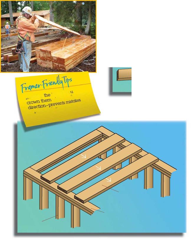
FRAMINGStep 1-Crown & Place Joists

Spread joists so crowns are in the same direction. The crown is the highest point of a curved piece of lumber.

If the joists are resting on a foundation instead of a stud wall, then a sill plate, or mudsill, would be attached to the foundation, and the joists would rest on the plate or sill.

_ showing te1®

FRAMING

Look for crown


Mark joist crown up


piste os 4° aovm


vtai№3


FRAMING

Joist


Double plate


Stud


Factors Affecting Permeability

Predicting the saturated permeability of soils or aggregates based on theoretical con­siderations has turned out to be difficult as permeability is dependent on a number of factors such as grading, void ratio, soil texture and structure, density and water tem­perature (Cedergren, 1977). Therefore, several empirical equations for estimating the permeability have been proposed in the past. These equations frequently include parameters linked to the grading curve of the material or their void ratio.

Hazen (1911) proposed an equation of the permeability of loose clean filter sand as:

K = cD2l0 (2.22)

where c is a constant that varies from 1.0 to 1.5 when the permeability K is in cm/s and the effective size D10 is in mm. Hazen’s equation is only valid for limited grain size distributions of sandy soils. A small quantity of silt or clay particles may change the permeability substantially. It is seldom a good means of estimating K as illustrated by Fig. 2.7.

Factors Affecting Permeability Подпись: (2.23)

Another form of equation that has been frequently used in estimating the perme­ability of sandy soils is based on the Kozeny-Carman equation (Das, 1997; Carrier, 2003):

Подпись: 3

Factors Affecting Permeability

10-

C

0)

и

Factors Affecting Permeability Подпись: 0.1 1 10 Effective size, d10 (mm) Подпись: 100

« 10-4

Fig. 2.7 Illustration of mis-match between Hazen’s estimation and measured values from road aggregates (adapted from Jones and Jones, 1989) where c is a constant. Samarasinghe et al. (1982) proposed a similar equation for normally consolidated clays:

en

K = c (2.24)

1 + e

where n and c are experimentally determined parameters. These equations are al­most certainly improvements overEq. 2.22.