Grading and Side Slopes
This section is concerned with the design of the slopes, ditches, parallel channels, and interchange grading. It incorporates into the roadside design the concepts of vehicular safety developed through dynamic testing. Designers are urged to consider flat foreslopes and backslopes, wide gentle ditch sections, and elimination of barriers.
Slopes. Several combinations of slopes and ditch sections may be used in the grading of a project. Details and use of these combinations are discussed in subsequent paragraphs. In general, slopes should be made as flat as possible to minimize the necessity for barrier protection and to maximize the opportunity for a driver to recover
|
TABLE 2.24 Recommended Pavement Widening on Horizontal Curves, ft, for WB-50 Design Vehicles
Conversions: 1 mi/h = 1.609 km/h, 1 ft = 0.305 m. Note: Values less than 2.0 ft may be disregarded. Multiply table values by 1.5 for three lanes and by 2.0 for four lanes. Source: Location and Design Manual, Vol. 1, Roadway Design, Ohio Department of Transportation, with permission. |
control of a vehicle after leaving the traveled way. Regardless of the type of grading used, projects should be examined in an effort to obtain flat slopes at low costs. For example, fill slopes can be flattened with material that might otherwise be wasted, and backslopes can be flattened to reduce borrow.
To better understand the various types of grading, it is necessary to become familiar with the concept of a clear zone. Clear zone is defined as the unobstructed, relatively flat area provided beyond the edge of the traveled way for the recovery of errant vehicles and includes any shoulders or auxiliary lanes (Ref. 1, 2). Chapter 6 discusses the roadside safety aspects of designing for the clear zone, including the use of barriers to shield objects in the clear zone. In the following paragraphs, four types of roadside grading are described. The designer must select the appropriate one for the roadway being designed.
|
|
Safety grading is the shaping of the roadside using 6:1 or flatter slopes within the clear zone area, and 3:1 or flatter foreslopes and recoverable ditches beyond the clear zone. Safety grading is used on interstate highways, other freeways, and expressways. Figures 2.17 and 2.18 show many of these details.
Clear zone grading is the shaping of the roadside using 4:1 or flatter foreslopes and traversable ditches within the clear zone area. Foreslopes of 3:1 may be used but are not measured as part of the clear zone distance. Clear zone grading is recommended
(A)
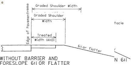 |
Treated width includes that portion of the shoulder improved with stabilized aggregate or better.
(B) Minimum barrier clearance.
(C) 3’on interstate, other freeways and expressways.
(D) Treated shoulder width may equal graded shoulder width in some cases.
FIGURE 2.13 Cross sections of shoulders showing graded and treated shoulder widths. Conversions: 2 ft = 0.61 m, 3 ft = 0.91 m. (From Location and Design Manual, Vol. 1, Roadway Design, Ohio Department of Transportation, with permission) for undivided rural facilities where the design speed exceeds 50 mi/h (80 km/h), the design hourly volume is 100 or greater, and at least one of the following conditions exists:
• The wider cross section is consistent with present or future planning for the facility.
• The project is new construction or major reconstruction involving significant length.
• The wider cross section can be provided at little or no additional cost.
|
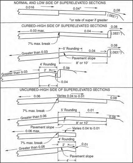
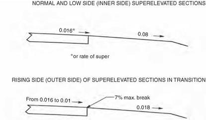
FIGURE 2.14 Recommended cross slopes and grade breaks for paved shoulders. Conversion: 1 ft = 0.305 m. (From Location and Design Manual, Vol. 1, Roadway Design, Ohio Department of Transportation, with permission) |
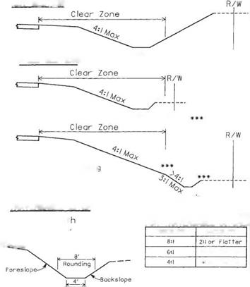
Figure 2.19 shows examples of clear zone grading and traversable ditches.
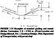
Standard grading is the shaping of the roadside using 3:1 or flatter foreslopes and normal ditches. Standard grading is used on undivided facilities where the conditions for the use of safety grading or clear zone grading do not exist. The designer should ensure that any obstacles within the clear zone receive proper protection. Figure 2.20 shows examples of standard grading and normal ditches.
|
|
HIGH SIDE OF SUPERELEVATED SECTIONS
|
2′- 6" |
|
FIGURE 2.15 Recommended cross slopes and grade breaks for bituminous surface treated or stabilized aggregate shoulders. Conversion: 1 ft = 0.305 m. (From Location and Design Manual, Vol. 1, Roadway Design, Ohio Department of Transportation, with permission) |
Barrier grading is the shaping of the roadside when a barrier is required for slope protection. Normally, 2:1 foreslopes and normal ditch sections are used. Figure 2.20 includes an example of barrier grading.
Rounding of Slopes. Slopes should be rounded at the break points and at the intersection with the existing ground line to reduce the chance of a vehicle’s becoming airborne and to harmonize with the existing topography. Rounding at various locations is illustrated in Figs. 2.17 to 2.20.
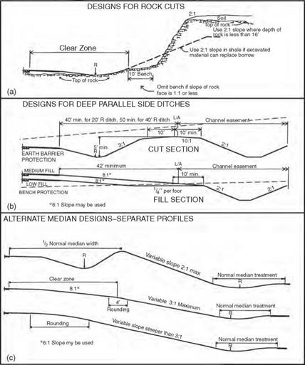
Special Median Grading. Figure 2.21c shows some examples of median grading when separate roadway profiles are used.
|
|
HIGH SIDE OF SUPERELEVATED SECTIONS
|
|
The break at the edge of the pavement shall not exceed 7%.
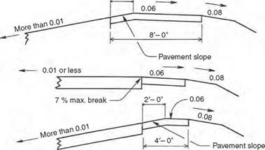
FIGURE 2.16 Recommended cross slopes and grade brakes for turf shoulders. Conversion: 1 ft = 0.305 m. (From Location and Design Manual, Vol. 1, Roadway Design, Ohio Department of Transportation, with permission)
Rock and Shale Slopes. In rock or shale cuts, the maximum rate of slope should be determined by a soils engineer. In deep rock or shale cuts where slopes are steeper than 1:1, a 10-ft-wide (3.05-m) bench should be provided between the top of the ditch back – slope and the toe of the rock face as illustrated in Fig. 2.21a. In shale cuts, the designer should not use backslopes steeper than 2:1 unless excessive waste would result. In any event, 2:1 slopes should be used for all shale cut sections less than 20 ft (7 m) in depth, and the bench should be omitted. In this discussion, depth of cut is measured from the top of shale or rock to the ditch flow line. Backslopes steeper than 2:1 should not be used in rock cuts until the depth exceeds 16 ft (5 m). In such cases the bench may be omitted.
Curbed Streets. Figure 2.22 shows typical slope treatments next to curbed streets.
Driveways and Crossroads. At driveways or crossroads, where the roadside ditch is within the clear zone distance and where clear zone grading can be obtained, the ditch and pipe should be located as shown on Fig. 2.23.

![]() CUT SECTION
CUT SECTION
URBAN INTERSTATE, OTHER FREEWAYS AND EXPRESSWAYS
I • 8:1 I
9-6- oitch
If backslope exceeds 3:1, use 40′ radius as shown above.
 SHALLOW CUT OR LOW FILL
•*
Recoverable Oitch
Slope transition between low fill design and medium fill design shall be such that the flowline of the roadside ditch does not turn toward the roadway.
![]()


 |
K – Clear zone – sj
Ml]}
MEDIUM FILL
Application of these sections may vary to avoid frequent slope changes and to maintain reasonably straight ditches.
FIGURE 2.17 Cross sections showing safety grading for four different conditions. Conversion: 1 ft = 0.305 m. (From Location and Design Manual, Vol. 1, Roadway Design, Ohio Department of Transportation, with permission)
Ditches. When the depth or velocity of the design discharge accumulating in a roadside or median ditch exceeds the desirable maximum established for the various highway classifications, a storm sewer will be required to intercept the flow and carry it to a satisfactory outlet. If right-of-way and earthwork considerations are favorable, a deep, parallel side ditch (see Fig. 2.21b) may be more practical and should be considered instead of a storm sewer. In some cases where large areas contribute flow to a highly erodible soil cut, an intercepting ditch may be considered near the top of the cut to intercept the flow from the
|
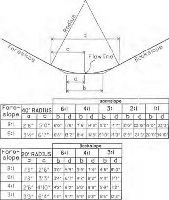
FIGURE 2.18 Details of ditch rounding for safety grading. Conversions: 1 ft = 0.305 m, 1 in = 0.0254 m. (From Location and Design Manual, Vol. 1, Roadway Design, Ohio Department of Transportation, with permission) |
outside and thereby relieve the roadside ditch. Constant-depth ditches (usually 18 in or 0.46 m deep) are desirable. Where used, the minimum pavement profile grades should be 0.24 to 0.48 percent. Where flatter pavement grades are necessary, separate ditch profiles are developed and the ditch flow line elevations shown on each cross section.
Parallel Channels. Where it is determined that a stream intercepted by the roadway improvement is to be relocated parallel to the roadway, the channel should be located beyond the limited access line (or highway easement line) in a separate channel easement. This arrangement locates the channel beyond the right-of-way fence, if one is to be installed. Figure 2.21b shows a parallel channel section. This does not apply to conventional intercepting erosion control ditches located at the top of cut slopes in rolling terrain.
In areas of low fill and shallow cut, protection along a channel by a wide bench is usually provided. Fill slope should not exceed 6:1 when this design is used, and maximum height from shoulder edge to bench should generally not exceed 10 ft (3.05 m). If it should become necessary to use slopes steeper than 6:1, guiderail may be necessary
 CUT SECTION
**■*
![]() Traversable Ditch
Traversable Ditch
(See below)
**For fill heights over!6′ use barrier gradlnc
Normal Ditch
 |
|
TRAVERSABLE DITCH
FIGURE 2.19 Examples of clear zone grading and traversable ditches. Conversion: 1 ft = 0.305 m. (From Location and Design Manual, Vol. 1, Roadway Design, Ohio Department of Transportation, with permission)
and fill slopes as steep as 2:1 may be used. In cut sections 5 ft (1.52 m) or more in depth, earth barrier protection can be provided. This design probably affords greater protection where very deep channels are constructed and requires less excavation. Where the sections alternate between cut and fill and it is desired to use but a single design, earth barrier protection is less costly if waste excavation material is available. Likewise, bench protection is less costly if borrow is needed on the project as a whole.
Earth bench or earth barrier protection provided adjacent to parallel channels should not be breached for any reason other than to provide an opening for a natural or relocated stream that requires a drainage structure larger in rise than 42 in (1.07 m). Outlet pipes from median drains or side ditches should discharge directly into the parallel channel.
Channels and toe-of-slope ditches, used in connection with steep fill slopes, are both removed from the normal roadside section by benches. The designer should establish control offsets to the center of each channel or ditch at appropriate points that govern alignment so the flow will follow the best and most direct course to the outlet. Bench width should be varied as necessary.
STANDARD GRADING
![]()
 |
||
FILL

![]()
 |
Slope may be flatter than l^^b’V Exceeds 16 if excess material and right – 0r> » ^ of-way are available at little cost. ‘•*/
Interchange Grading. Interchange interiors should be contour-graded so that maximum safety is provided and the least amount of guiderail is required. Figures 2.24 and 2.25 show examples. The generous use of flat slopes (6:1 or flatter) will also be easier for maintenance crews to work with. Sight distance is critical for passenger vehicles on ramps as they approach entrance or merge areas. Therefore, sight distance should be unobstructed by landscaping, earth mounds, or other barriers on the merging side of the vehicle.
Crossroads. At a road crossing within an interchange area, bridge spill-through slopes should be 2:1, unless otherwise required by structure design. They should be flattened to 3:1 or flatter in each corner cone and maintained at 3:1 or flatter if within the interior of an interchange. Elsewhere in interchange interiors, fill slopes should not exceed 3:1.
Ramps. Roadside design for ramps should be based on Fig. 2.17 or 2.18, depending on the mainline grading concept.
|
FIGURE 2.21 Examples of special designs for grading. (a) Designs for rock cuts. (b) Designs for deep, parallel side ditches. (c) Alternate median designs. Conversion: 1 ft = 0.305 m. (From Location and Design Manual, Vol. 1, Roadway Design, Ohio Department of Transportation, with permission) |
Gore Area. Gore areas of trumpets, diamonds, and exteriors of loops adjacent to the exit point should be graded to obtain slopes of 6:1 or flatter, which will not endanger a vehicle unable to negotiate the curvature because of excessive speed.
Trumpet Interiors. Interior areas of trumpets (Fig. 2.24) should be graded to slopes not in excess of 8:1, sloping downward from each side of the triangle to a single, rounded low point. Roadside ditches should not be used. Exteriors should be graded in accordance with mainline or ramp standards.
 |
To be used on clear zone grading projects where the roadside ditch flowline is located within the clear zone distance
FIGURE 2.23 Slopes and ditches at driveway and crossroad in cut or low fill for use on clear zone grading projects where ditch is within clear zone distance. (From Location and Design Manual, Vol. 1, Roadway Design, Ohio Department of Transportation, with permission)
![]()
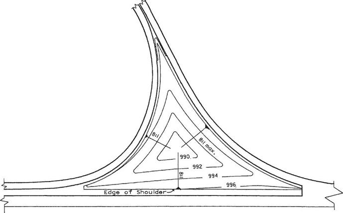
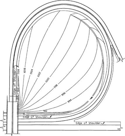
Loop Interiors. In cut, the interior of a loop should be graded to form a normal ditch section adjacent to the lower part of the loop, and the backslope should be extended to intersect the opposite shoulder of the upper part of the loop. This applies unless the character and the amount of material or the adjacent earthwork balances indicate that the cost would be prohibitive. Roadside cleanup and landscaping should be provided in undisturbed areas of loop interiors. If channels are permitted to cross the loop interior, slopes should not be steeper than 4:1. Figure 2.25 shows an example.
Diamond Interiors. If the location of the ramp intersection at the crossroad is relatively near the main facility, a continuous slope between the upper roadway shoulder and the lower roadway ditch will provide the best and most pleasing design. If the ramp
|
FIGURE 2.25 Contour grading of loop interior in cut section at interchange with contour elevations shown in feet. Conversion: 1 ft = 0.305 m. (From Location and Design Manual, Vol. 1, Roadway Design, Ohio Department of Transportation, with permission) |
intersection at the crossroad is located a considerable distance from the main facility, then both ramp and mainline roadsides should have independent designs, until the slopes merge near the gore.
If the quadrant is entirely, or nearly so, in cut, the combination of a 3:1 backslope at the low roadway ditch and a gentle slope down from the high roadway shoulder will provide the best design in the wide portion of the quadrant. Approaching the gore, the slopes should transition to continuous 4:1 and 6:1 or flatter slopes. Quadrants located entirely in fill areas should have independently designed roadways for ramp, mainline, and crossroad. Each should be provided with normal slopes not greater than 3:1, with the otherwise ungraded areas sloped to drain without using ditches. If the quadrant is located part in cut and part in fill, the best design features a gentle fill slope at the upper roadway and a gentle backslope at the lower roadway, joined to a bench at the existing ground level that is sloped to drain. The combination of a long diamond ramp having gentle alignment with a loop ramp in the same interchange quadrant is not to be treated as a trumpet. Each ramp should be designed independently of the other in accordance with the suggested details set forth above.
Although bridge engineering is discussed in Chap. 4, information on pertinent physical dimensions is presented here. Lateral clearance at underpasses and vertical clearance over roadways, as used in Ohio, are given in Table 2.25 for new and reconstructed bridges. The table notes provide a good insight into when variations from the standards are allowed.




Leave a reply