Drive Profile Design

Drive profiles on uncurbed roadways should slope down and away from the pavement

edge at the same slope as the graded shoulder. Any vertical curve should be developed

Drive Profile Design

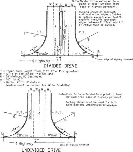
FIGURE 2.57 Designs for shopping center and industrial drives. Conversions: 1 ft = 0.305 m, 1 in = 25.4 mm. (From Location and Design Manual, Vol. 1, Roadway Design, Ohio Department of Transportation, with permission)

outside the normal graded shoulder width. Vertical curve lengths should be 10 to 20 ft (3.0 to 6.1 m), depending on the grade differential. Under normal circumstances, rural drive grades should not exceed 10 percent, with 8 percent the preferred maximum.

The drive profiles for curbed roadways were developed using the design vehicle described in Fig. 2.50. The profile criterion shown provides clearance for this vehicle when its springs are completely compressed. If conditions of a particular driveway do not meet the cross-section criteria listed below, a template of the design vehicle can be used to design the driveway profile.

For tree lawns 6 ft (1.8 m) or wider, the ramp grade from the gutter to the edge of the sidewalk should be 1 in/ft (8.3%) or less for normal cross-section design. Figure 2.50 shows this condition for the following cross-section conditions:

• Sidewalk and tree lawn slope of /4 in/ft (2.1%) and

• A 6-in (150-mm) curb height with pavement slope of %s or % in/ft (1.6 or 2.1%) or

• Type 2 curb and gutter with pavement slope of %s in/ft (1.6%)

If the cross-section design does not meet the above conditions (has sharper grade breaks), the profile should be designed using a template of the design vehicle.

For tree lawns less than 6 ft (1.8 m) wide, Fig. 2.51 shows the profile treatment. Clearance for the design vehicle is achieved by depressing the sidewalk 1 in (25.4 mm) at the driveway. The sidewalk cross slope of % in/ft (2.1%) is retained. The design may be used directly with curbed highways having cross-section criteria as listed above and the profile conditions of Fig. 2.50. For other cross sections, a template of the design vehicle may be used to design the profile.

Figure 2.51 shows an isometric view and profile for a driveway where only a 3-ft (0.9-m) tree lawn is available. This design is shown not because it is desirable, but because right-of-way width and property development may require this type of design. Whenever feasible, the tree lawn should be 8 ft (2.4 m) or wider. Where the total width of tree lawn and sidewalk is less than 6 ft (1.8 m), the minimum 3-ft (0.9-m) apron designs are inappropriate and cannot be used, as they extend curb or sharp flares into the sidewalk area. For this condition, the sidewalk and curb are transitioned to meet the drive profile as shown on the lower portion of Fig. 2.51. The profile of the drive meets the 1-in (25.4-mm) depressed grade of the sidewalk, as shown in the drive profile.

The tree lawn and walk design shown in Figs. 2.50 and 2.51 will keep storm water, flowing at the curb design height or less, from flowing over the sidewalk. If it is nec­essary to lower the curb and sidewalk more than 1 in (25 mm), the drainage condition should be checked thoroughly.

Commercial drive profiles usually use a dropped curb across the approach. However, some commercial drives serving large traffic generators may be designed as at-grade intersections, without dropped curbs, because of their high traffic volumes.

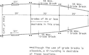
Figure 2.58 shows the recommended grade controls for commercial driveways. The grade should be as flat as possible and still meet drainage requirements. The 20-ft

Drive Profile Design

FIGURE 2.58 Profiles for commercial drives. Conversions: 1 ft = 0.305 m, 1/4 in/ft = 21 mm/m. (From Location and Design Manual, Vol. 1, Roadway Design, Ohio Department of Transportation, with permission)

Drive Profile Design

FIGURE 2.59 Commercial design vehicle showing wheel spacings and clearances. Conversions: 1 ft = 0.305 m, 1 in = 25.4 mm. (From Location and Design Manual, Vol. 1, Roadway Design, Ohio Department of Transportation, with permission)

(6.1-m) length between grade breaks is required by the low clearance and the long axle spacing of the commercial design vehicle shown in Fig. 2.59. Tree lawn profile design should be in accordance with Figs. 2.50 and 2.51. The grade break at the face of the curb is critical for some commercial vehicles, and the cross-section requirements for residential drives on curbed streets should be used.

Capacitance Measurements

Capacitive sensors measure the resonant frequency of an inductance-capacitance (LC) tuned circuit where the soil located in between two flat waveguides is the dielectric material. The inductance is kept constant and the resonant frequency f measured and therefore the capacitance can be calculated from

2n ^ e

where Le is the inductance and Ce is the capacitance. The capacitance Ce is a measure of the relative bulk dielectric constant of the soil and is a function of the water content of the soil (Veenstra et al., 2005). As with all dielectric moisture-based sensors, calibration is necessary for an accurate determination of the water content. Starr and Paltineanu (2002) give an overview of the current capacitance methods, their instrumentation and procedures.

Nail rim joists first

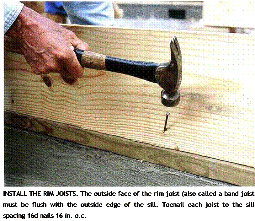
Rim joists form the exterior of the building and are the first joists to he installed. The lay­out of other joist locations are marked on the top edges of the rim joists. Cut the rim joists to length and toenail each one flush with the outside of the sill. I drive one I6d nail every 16 in. around the perimeter (see the photo below). In earthquake and high-wind areas, code may require that the rim also be secured to the sill with framing anchors, so check with
your local building inspector. If there are no vents in the foundation, they can be cut into the rim joists. A standard screened vent fits in a 41^-in. by 14^-in. opening.

If you’re framing a floor with 1-joists, you’ll probably use the specially made OS В rim joists supplied with your I-joist order. Install rim joists along only one side of the house. Then lay the I-joists flat across the sills, butting the end of each joist fast against the installed rim joist. The opposite ends of the joists will extend over the sill at the other side of the house. You can now snap a line across the ends to establish where the I-joists need to be cut. A simple jig, explained in the sidebar on the facing page, makes it easy to cut the joists smoothly and accurately. After cutting the I-joists to length, complete the rim joist installation.

Joist layout goes quickly

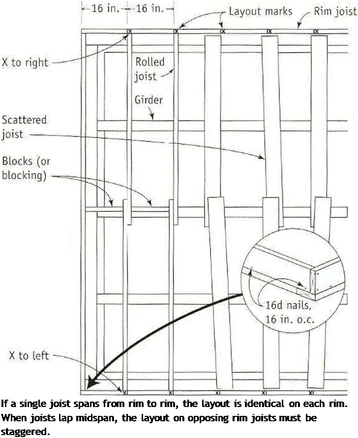
When a single joist spans a house from edge to edge, the layout is identical on parallel rims, lust hook a long tape on the end of the rim joist and make a mark on top every 16 in.

(32 in., 4cS in., etc.) down the entire length. Put an “X” next to each mark to indicate which side of the line the ioist goes on.

When the joists la}-» over a central girder or wall, the layout on the opposing rim joists must be staggered. On one rim joist, mark the 16-in. o. c. locations with an “X" to the right; on the opposite side, lay out the joists with an “X" to the left. T his allows the joists to lap and nail over a girder or crib wall, where they will be stabilized with blocks (see the illustration on the facing page).

Your joist layout may include openings (called headouts) for a stairway or to provide clearance for plumbing or vents. Your plans

Nail rim joists firstNail rim joists first

Tool Talk I-JOIST CUTTING GUIDE

I-JOISTS ARE AWKWARD to cut because the top and bottom chords are wider than the web. To overcome this difficulty, make a simple jig with УИп.-thick plywood. Cut a rectangular piece of plywood to fit between the chords and serve as the base of the jig. Screw a longer piece to the first p’ece, positioning it to guide a 90-degree cut. The edge of the top piece guides the base of the circular saw, as shown in the photo. Lay the guide on the I-joist, set the saw on it, and make a square cut. It’s that simple.

CUT I-JOISTS WITH A GUIDE. Scrap sheathing that is nailed or screwed together creates an effective guide for cutting I-joists. [Photo by Roe A. Osborn, courtesy Fine Homebuilding magazine, The Taunton Press. Inc.]

Подпись: JOIST LAYOUT Подпись: If a single joist spans from rim to rim, the layout is identical on each rim. When joists lap midspan, the layout on opposing rim joists must be staggered.

should show these openings, but it s always a good idea (and it could save a lot of time and effort) to check with the plumber. A common mistake is leaving insufficient room between the joists for the tubs trap and the toilet’s

drain. You mav need to frame a headout to

і

make room for plumbing. For headout tram ing details, see the sidebar on p. 67. When framing with 1 joists, remember that, like any other type of engineered joist, they cannot be notched or cut midspan without destroying their structural integrity.

Cut the joists in place

If you trust your eye, try cutting 2x joists in place rather than measuring each one individ­ually. As you become comfortable using a cir­cular saw, you’ll be able make a square cut without using a square (see the sidebar on p.68). This technique is definitely worth learning. Over the course of framing a house, it will save a significant amount of time.

POTABLE WATER SYSTEMS CALCULATIONS

  POTABLE WATER SYSTEMS CALCULATIONS

When you are dealing with large buildings, there will usually be detailed riser diagrams, blueprints, and specifications available to outline your work. House plans rarely show much more than fixture placement for plumbing. They frequently have wiring diagrams, but most don’t show a piping schematic. Long story short, commercial build­ings are usually laid out for the master plumber by a designer.


water service or a 1-inch water service into the building. Primary piping would be three-quarters of an inch in diameter, with branch piping having a diameter of one – half an inch. A rule of thumb is that not more than two fixtures should be served off of a single half-inch branch. This is a simple system without much of a load. But, what would happen if the building you were working with was an office building with four stories and a basement? There would be much more to consider, and I will pro­vide you with a sizing example for this type of building in a few moments.

Many factors can come into play when sizing a water distribution system. The type of pipe or tubing being used is one factor. The friction loss among various


► sensible shortcut


Residential sizing is simple. Figure a 4-inch sewer pipe, plan on no more than two toilets on a 3-inch drain, and run three-quarter-inch water mains with no more than two water branches on a half-inch pipe. If you do this, you are unlikely to go wrong.


29


POTABLE WATER SYSTEMS CALCULATIONSPOTABLE WATER SYSTEMS CALCULATIONS

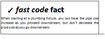
types of piping varies. Even the types of valves installed on the piping will make a difference in friction loss. Most important to sizing is the fixture-unit load on the system and the components of the system. In most cases, a job will start with one size of pipe and the pipes will grow increasingly smaller in di­ameter as they serve the various plumbing fixtures. Also, the rise of piping and the length of pipe runs will affect the sizing of a system.

Plumbing systems for most large jobs are designed by professionals who don’t work as plumbers. However, when you are remodeling a building,

Подпись:adding onto an existing system, or working without detailed blueprints, the need for knowledge about pipe siz­ing may become very important. Siz­ing is also an element of most licensing exams for plumbers, so this is another good reason to learn and understand the principles used in sizing systems.
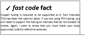
Подпись:Two of the major plumbing codes have graciously agreed to allow me the use of excerpts from their codebooks to better show you rule and regulations pertaining to pipe sizing. Both of the codes offer sizing examples in their codebooks. Your local code may also offer similar sizing data. Once you have established numbers to work with, such as fixture-unit ratings, sizing a water system is a manageable task.

Safety on the Job PNEUMATIC NAILERS

Safety on the Job PNEUMATIC NAILERS

FOR THE MOST PART, volunteers who help build Habitat houses use only hammers to drive nails. But these days, buildings are often nailed together with all kinds of pneumatic nailers. These tools have been around for 40 years or so and are generally good, reliable tools. Models are available for framing, fin­ish work, siding, and shingling. However, as with all power tools, there are basic safety considerations to keep in mind.

♦ Treat a pneumatic nailer with respect. Be mind­ful of what you are doing. Never point a nailer at yourself or at others.

♦ Read and follow the instruction manual regarding

its maintenance and use.

♦ Don’t walk around with your finger on the trigger. You could bump the nailer against your leg, releasing the safety and accidentally firing a nail.

♦ Adjust the air pressure as needed. Larger nails require more pressure.

♦ Wear safety glasses or goggles.

♦ Disconnect the nailer from the air compressor before clearing a jammed nail.

♦ When nailing on a sidewall, don’t hold the nailer in front of your face. Hitting a metal strap or other hardware beneath the surface could cause the nailer to recoil into your face with consider­able force.

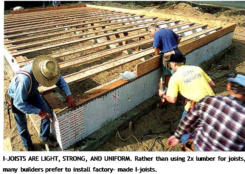
Safety on the Job PNEUMATIC NAILERSПодпись: I-JOISTS ARE LIGHT, STRONG, AND UNIFORM. Rather than using 2x lumber for joists, many builders prefer to install factory- made I-joists.

STEP6 Install the Joists

Joists span a house from edge to edge, provid­ing support (and a nailing surface) for the subfloor and a platform for the walls. Many older houses were built with undersized joists that were unable to keep floors and ceilings from sagging. Building codes today help ensure that joist sizing and spacing are more than adequate to keep floors rock solid yet resilient. Joists are normally spaced to allow for the most efficient use of full-size (4-ft. by 8-ft.) sheets of OSB or plywood. Joists cut from 2x lumber are generally spaced 16 in. or 24 in. o. c. Engineered wood I-joists can be spaced on centers of 12 in., 16 in., 19.2 in., or 24 in.

Solid lumber vs. engineered I-joists

Up until 20 years ago, most of the floors in this country were built with standard 2x joists. These days, more floors are being built with engineered I-joists. So named because of their Tprofile, I-joists have plywood top and bot tom chords connected by an OSB web (see the
photo above). They offer several advantages over solid lumber. Being an engineered prod­uct, they are knot-free and can span long dis­tances without interior support. I-joists don’t swell, shrink, crack, or warp the way solid lumber does. They are much lighter and easier to carry than 2x joists. And they’re uniform in size. In a load of 2x joists, you might find up to % in. of variation in joist width. I-joists don’t vary; once installed, they create a dead-

Подпись: Helping HandПодпись: Patterns save time. When cutting multiple identical pieces of framing members, such as joists, it is common to use a pattern piece. Cut one piece to the correct length, then lay it on top of the next piece to be cut and mark that one. Write the word "pattern" on the original piece.Подпись: INSTALL THE RIM JOISTS. The outside face of the rim joist (also called a band joist) must be flush with the outside edge of the sill. Toenail each joist to the sill, spacing 16d nails 16 in. o.c.

level floor. Nails driven through the sheathing into the top chord arc less likely to come loose and create a squeaky floor, especially when the sheathing is applied with adhesive. In terms of price, they are competitive with standard – dimension lumber. Installation details foi­l-joists are slightly different than those for 2x joists. I ‘ll cover those differences just ahead.

RUNNING THE NUMBERS

Running the numbers of pipe fitting is not always necessary to complete a job. If you have the experience and the eye to get the job done, without going through mathematical functions, that’s great. I admit that I rarely have to use sophisticated math to figure out my piping layouts. But, I do know how to hit the mark right on the spot when I need to, and so should you. Accuracy can be critical. If you don’t invest the time to learn the proper methods for figur­ing offsets, you may cut your career opportunities short. Believe me, you owe it to yourself to expand your knowledge. Sitting still can cost you. Reach out, as you are doing by reading this book, and expand your knowledge.

Some people see plumbers and pipe fitters as blue-collar workers. This may true. If it is, I’m proud to wear a blue collar. Yet, if you proceed in your career, you may own your own business, and this will, by society’s standards, graduate you to a white collar. As far as I am concerned, the color of a per­son’s collar has no bearing on the person’s worth. Blue collar or white collar, individuals are what they are. We all bring something to the table. Yes, some people do prosper more than others, and education does play a role in most career advancements.

You may or may not need what you’ve learned in this chapter. However, knowing some simple math and having access to the tables in this chapter will probably give you an edge on many of the people you work with or compete with. Like it or not, making a living in today’s world is competitive. So why not be as well prepared as possible? Okay, enough of the speech, let’s move into the next chapter and study calculations that deal with welding fabrica­tion and layout.

Supply Ventilation Dilutes Pollutants Throughout the House

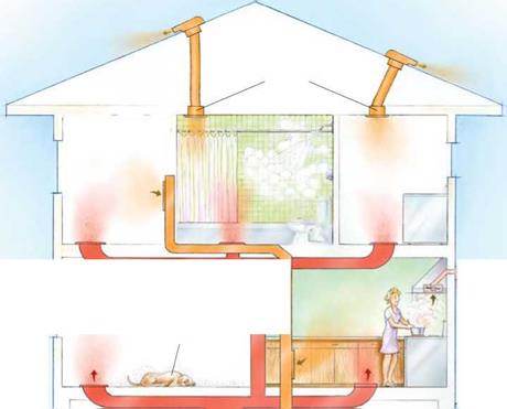
A supply system has the advantage of allowing you to select where the air comes from and how it is distributed throughout your home. For example, fresh air can come from a duct run connected to the return plenum of an HVAC system (see the draw­ing on the facing page). This way, outdoor air is pulled into the house through the air handler whenever it operates. Such an air intake must have controls (such as a timer or cycler) to turn on the air handler to make sure there is enough ventilation air. This sys­tem also should have a damper to prevent overventilating when the heating or cooling system is operating most of the time (very hot or very cold weather). Without these controls, this supply system is just a hole in the return duct, worse than a leaky house.

Supply systems must temper ventilated air to moderate temperatures in all but the mildest climates. When there is no heating or cooling call, the system above does this by running the air handler and mixing un­conditioned outside air with large volumes of conditioned indoor air. While this process tempers the outside air, it uses a lot of elec­tricity because the air-handler fan is over­kill for the amount of ventilation air being sucked in.

Supply Ventilation Dilutes Pollutants Throughout the HouseA Supply System Removes Bad Air and Brings in Fresh

Houses with a forced-air heating system or with central air-conditioning have a built-in air-distribution network. A supply system uses it to distribute fresh out­side air through the existing ductwork. But you still need exhaust fans in wet rooms. The best approach is a quiet, continuously running multiport vent fan in the attic that draws from several rooms (see p. 36).

Exhaust fan

Подпись: Air polluterSupply Ventilation Dilutes Pollutants Throughout the HouseПодпись:A separate range-hood vent fan is the simplest, best way to deal with contaminants from cooking.

Fresh air is brought in through a separate duct running from the outside to the return-air plenum of the HVAC unit.

Supply Ventilation Dilutes Pollutants Throughout the HouseACTIVE INTAKE

With a duct from outside the house to the furnace’s return-air plenum, fresh makeup air is drawn into the house by the furnace fan. A temperature – and humidity-sensing damper system (pic­tured at left) installed in the duct curtails airflow during very hot and humid or very cold weather.

A Balanced System Removes Bad Air, Brings in Fresh, and Can Save Heat (or Cold)

Supply Ventilation Dilutes Pollutants Throughout the HouseПодпись: lit Ф r*. T -1 І J МТ1 Подпись: A separate range-hood vent fan is the simplest, best way to deal with contaminants from cooking.Подпись: Outside-air intake sucks fresh air into the HRV, where it is tempered before it enters the return-air plenum.Подпись: Return air for furnaceSupply Ventilation Dilutes Pollutants Throughout the House

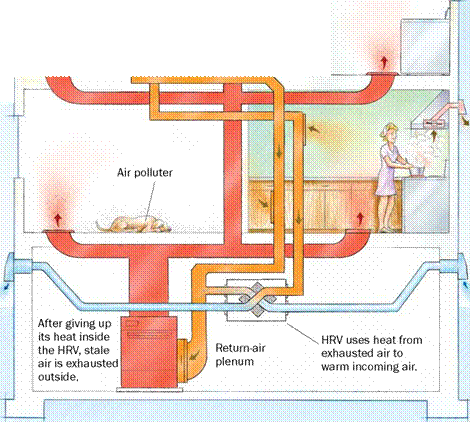
The problem with exhausting stale air from your house is that you’ve likely paid good money to heat or cool that air, and venting it directly outside is like throwing away money. A balanced system with a multiport vent fan (from $185 at www. sheltersupply. com

or www. iaqsource. com) channeling all exhaust through some type of heat

exchanger can mitigate the energy loss.

Supply Ventilation Dilutes Pollutants Throughout the House

Supply Ventilation Dilutes Pollutants Throughout the HouseACTIVE EXHAUST AND INTAKE WITH ENERGY RECOVERY

The best approach to whole-house ventilation employs either a heat-recovery venti­lator (HRV, from $700; see the photo at left) in cold climates or an energy-recovery ventilator (ERV, from $800) in hot climates. These units, which can be incorporated into a house with or without existing ductwork, bring in fresh air and exhaust stale air. In addition, an HRV tempers incoming air with outgoing air, thus lowering the amount of energy necessary to condition the fresh air. An ERV looks and functions similarly, but it dehumidifies and cools hot, humid air, which reduces the load on the air conditioner.

America’s First Residential Ventilation Standard

U

ntil recently, not much had changed since 1631, when England’s King Charles I passed the first ventilation code (your dwelling had to have operable windows taller than they were wide). Because today’s houses aren’t leaky enough to provide fresh air, the American Society of Heating, Refrigerating and Air-Conditioning Engineers wrote a ventilation standard. ASHRAE 62.2 is a minimum standard applicable to both new and existing homes (including small multifamily ones). Keep in mind that 62.2 is a standard, not a code. Think of it as a recommendation that might lead to a new code requirement.

THE MAJOR REQUIREMENTS OF 62.2:

•WHOLE-HOuSE MECHANICAL VENTILATION

Ventilation can be achieved with an exhaust, supply, or balanced ventilation system. Ventilation airflow, mea­sured in cubic feet per minute (cfm), must increase with the size of the house and the number of occupants. The 62.2 standard recommends minimum ventilation rates of 45 cfm for 2- to 3-bedroom houses up to 1,500 sq. ft.;

60 cfm for 2- to 3-bedroom houses between 1,500 and

3,0 sq. ft.; and 75 cfm for 4- to 5-bedroom houses between 1,500 and 3,000 sq. ft.

• mechanical exhaust in kitchens

AND BATHROOMS

In addition to the whole-house ventilation requirement: Kitchen: a user-operable vented range hood of at least 100 cfm; or a fan giving 5 kitchen air changes per hour of continuous or intermittent exhaust.

Bathroom: a user-operable fan of at least 50 cfm; or a continuously operating 20-cfm exhaust fan.

• minimum performance standards for fans

Volume: Fan’s airflow rates must be rated by a third party. Noise: Continuously operating fans should be 1 sone or less; intermittent-use kitchen and bath fans cannot exceed 3 sones.

•AIRTIGHT GARAGE DucT SYSTEMS

Air handlers or return ducts in an attached garage must be tested for tightness. While tight ducts save energy, 62.2 sets only minimum requirements to protect indoor-air quality.

• particle FILTRATION upSTREAM OF AIR HANDLERS

Dirty ducts and coils can become a pollution source, so 62.2 requires pleated furnace filters (MERV 6 or better). To clean the air inside a house, more-aggressive filtration is needed.

Asphalt Shingles

On residences, two primary types of asphalt shin­gles are used. Until recently, most were three-tab shingles with two slots dividing the exposed part of the shingle into thirds. But today, laminated shingles (also called architectural and dimension­al shingles) are gaining in popularity. Consisting of two bonded layers, laminated shingles are thicker, more wind resistant, and somewhat easi­er to install because they have a random pattern,
with no shingle cutouts to line up. When installed, they look distantly like wood shakes.

MATERIALS: ROUGH NUMBERS

Shingle dimensions vary by maker. Three-tab shingles are typically 12 in. by 36 in. Laminated shingle dimensions are often metric, roughly 13 in. by 40 in. Most shingles are installed with a 5-in. exposure, though shingles with metric dimensions may specify a 5%-in. exposure.

Calculating shingles needed for a complex roof is.. .complex. Begin by measuring the roof accu­rately, making a to-scale sketch on graph paper as you measure. Note valleys, ridges, chimneys, skylights, plumbing vents, and other elements that require flashing, waterproof membranes, or special attention. With that sketch, a building sup­plier can develop a final materials list for shingles, nails, underlayment, flashing, vents, and so on.

Asphalt shingles come three to five bundles to the square (100 sq. ft.), depending on shingle dimensions. Thus you need to calculate the square footage of roof surfaces and divide that number by 100 to get the number of squares needed to shingle the field. In addition, you’ll need materials to reinforce shingles along eaves and rake edges—either by installing a double layer of shingles along the roof perimeter or by applying a heavy starter strip before shingling.

If you’re installing laminated shingles, use three-tab shingles as an underlayer along the eaves and rakes. For this purpose, three-tab shin­gles are far cheaper than laminated shingles and will lie flatter. If you’re installing woven valleys, you’ll interweave roughly one bundle of shingles per 16 linear (lin.) ft. of valley. Finally, add two extra bundles for waste, ridge and hip caps, and future repairs.

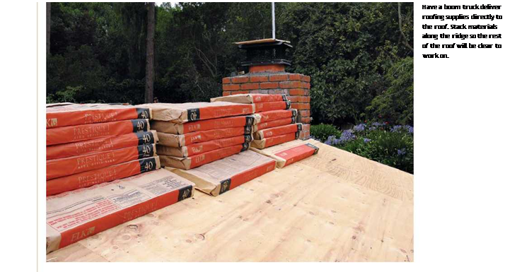
Shingle colors often vary from one production lot to another. So, to avoid having a new roof with a patched-together look, specify that all bundles come from the same lot when you order. Then when your order arrives, check the lot num­bers on the bundles and open a few bundles from different lots. If lot numbers don’t match and the color variation is noticeable, call the supplier and ask it to rectify the situation. If the color varies only slightly, you might mix lots every other shin­gle during installation. Finally, have shingles delivered directly to the roof. Many suppliers will place bundles on the roof by means of truck booms or conveyor belts.

Roofing nail quantities vary according to method: hand nailing, power nailing, or some combination of both. Typically, use 4 nails per shingle, or about 2 lb. of nails per square if you’re hand nailing. However, high-wind areas require

image159
6 nails per shingle or 3 lb. per square. Roofing nails come in 5-lb. and 50-lb. quantities. Boxes of pneumatic nails typically contain 120 nails per coil and 60 coils per box. At 4 nails per shingle, you’ll need about 313 coils (400 nails) to attach a square of shingles.

Use corrosion-resistant roofing nails at least 1 !4-in. long for new roofs; 113-in. nails if you’re roofing over a previous layer. Ideally, nails should sink three-quarters into sheathing or stop just short of penetrating all the way through for h-in.- to 53-in.-thick sheathing. Hence, if the roof has an exposed roof overhang (you can see the under­side of the sheathing), use M-in. ring-shank nails

Подпись:image161

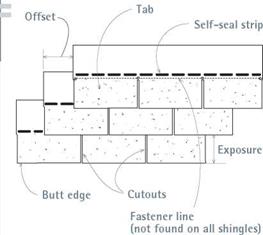
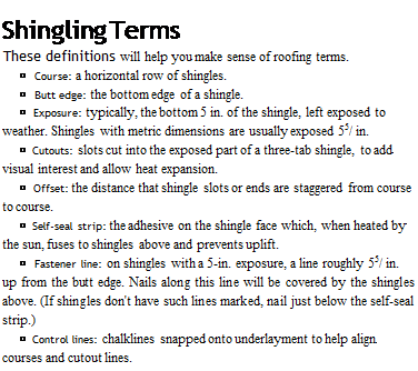
Подпись: Shingling Terms These definitions will help you make sense of roofing terms. ► Course: a horizontal row of shingles. ► Butt edge: the bottom edge of a shingle. ► Exposure: typically, the bottom 5 in. of the shingle, left exposed to weather. Shingles with metric dimensions are usually exposed 55/ in. ► Cutouts: slots cut into the exposed part of a three-tab shingle, to add visual interest and allow heat expansion. ► Offset: the distance that shingle slots or ends are staggered from course to course. ► Self-seal strip: the adhesive on the shingle face which, when heated by the sun, fuses to shingles above and prevents uplift. ► Fastener line: on shingles with a 5-in. exposure, a line roughly 55/ in. up from the butt edge. Nails along this line will be covered by the shingles above. (If shingles don't have such lines marked, nail just below the self-seal strip.) ► Control lines: chalklines snapped onto underlayment to help align courses and cutout lines.

Many local codes don’t allow pneumatic staples to attach roofing, and for good reason. Slight variations in compressor-line pressure or setting depth will blow staples right through shingles, and even if staple depth is correct, shingles can easily work loose from the skinny crown holding them down. Roofing nails are vastly superior.

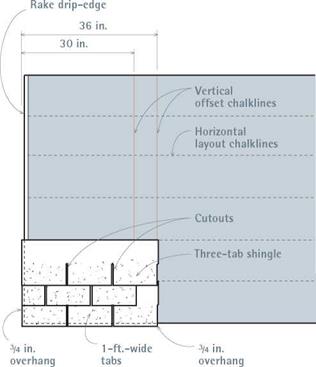
Подпись: PROTIP Score shingles on the backside, using a utility knife. If you try to cut through the granules on the front, the blade will go awry and soon dull. When you score along a straightedge and snap along the cut, you'll get a straight, clean edge. 1111 Подпись: I Laying Out Three-Tab Shinglesimage162"Подпись: Aligning three-tab shingle cutouts can be as easy as snapping two vertical chalklines 6 in. apart. Because individual shingle tabs are 1 ft. wide, a 6 in. offset will line up shingle cutouts every other course.(along the overhang) for a new roof; 1-in. ring- shank nails for roofovers.
When ordering, don’t forget tabbed roofing nails for underlayment and metal-compatible nails for attaching flashing or valley clips.

SHINGLE LAYOUT

We’ll assume that the roof has been stripped of old shingles, that failed sheathing has been replaced, and that the roof is safe to walk on.

Reconnoiter the roof. Use a tape measure to see whether the roof is square, the ridge is parallel to eaves, the rake edges are parallel, and whether— overall—the width of the roof requires shifting shingle courses left or right. To determine square, measure diagonally from both ends of the ridge down to the opposite eaves corner; if the readings are roughly equal, chances are the roof is square. If the ridge is parallel to eaves within h in., run shingle courses right up to the ridge. But if ridge – to-eaves readings differ by % in. or more, you’ll need to compensate by adjusting shingle – exposures as you approach the ridge.

The last two measurements, for parallel rakes and roof width, are of most concern if you’re
installing three-tab shingles. Because three-tab shingle patterns align vertically, avoid cutting shingle tabs less than 2 in. wide along either rake edge—such short tabs look terrible. It’s far better to shift the shingle layout (and thus the vertical control lines) slightly right or left, so the shingle piece is larger. For additional strategies for installing three-tab shingles, see Mike Guertin’s fine book, Roofing with Asphalt Shingles.

Establishing control lines. After installing drip – edges along the eaves, many pros measure only once, to establish a horizontal control line paral­lel to the eaves, to which they nail the shingle starter course. After the starter course is down, they put away their tape measure and use only the exposure gauge of their pneumatic nailer or shingle hatchet to position successive courses.

But, to keep courses evenly spaced and straight, you should mark horizontal lines at reg­ular intervals on the underlayment. If your shingle exposure is 5 in., snap chalklines for every course or every third course—whatever works for you. Snapping lines doesn’t take much time and will help ensure professional-looking results.

If you’re installing three-tab shingles, it’s also wise to snap a pair of parallel, vertical control lines 6 in. apart, to line up the slots of alternating shingle courses, as shown in "Laying Out Three – Tab Shingles,” at left. With a 6-in. offset, the slots of every other course line up, creating a strong visual pattern. If slots don’t align, the installation will look sloppy. On the other hand, laminated shingles have no slots to align and so don’t need vertical control lines.

WOOD I-JOISTS FOR LOADS

Squash Blocks & Blocking Panels

WOOD I-JOIST CONNECTIONS

Blocking & Backer Blocks

WOOD I-JOISTS FOR LOADSWOOD I-JOISTS FOR LOADSWOOD I-JOISTS FOR LOADS

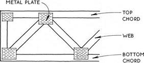
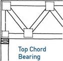
Four-by-two wood floor trusses are made up of small members (usually 2x4s) that are connected so that they act like a single large member. The parallel top and bottom chords and the webs are made of lumber held together at the intersections with toothed metal plates.

The open web allows for utilities to run through the floor without altering the truss. Round ducts from 5 in. to 16 in. in diameter can be accommodated, depending

on the depth of the truss. Truss depths vaiy from 10 in. to 24 in., with spans up to about 30 ft. Like I-joists, floor trusses are practical for long spans and simple plans, but difficult for complicated buildings.

Floor trusses are custom manufactured for each job, and cannot be altered at the site. Bearing walls, floor openings, and other departures from the simple span should always be engineered by the manufacturer.

SKYLIGHT AND RIDGE FLASHING

Skylight flashing is discussed in Chapter 6, where you’ll see an installation from framing to flashing. As a general rule, follow the instructions in the flashing kit provided by the skylight manufacturer.

Traditionally, ridges were flashed with a con­tinuous strip of 12-in.-wide, 30-lb. building paper folded lengthwise, which straddled the ridge and overlapped the top courses of shingles. The build-

Подпись: PRO"ГIP Before inserting counter-flashing, blow or brush out debris from the mortar joints. If your air-compressor hose can reach the roof, use it. Otherwise, insert a piece of plastic tube in the joint and just blow. Wear goggles—and when the tube is in place, don't inhale. 1111 Подпись: 2. This grinder is poised to grind out an old chimney mortar joint. Once the abrasive wheel hits mortar, you'll see nothing but grit. So wear goggles.

Подпись: 4. Finally, run a bead of urethane caulk such as Vulkem® 116 to fill the joint and seal out water. Once the caulk has set a bit, you can tool it with your thumb.

CHIMNEY FLASHING

image156

1. As you roof along a chimney, alternate shingles and L-shaped pieces of step-flashing. Counterflashing will cover the tops of the step-flashing. For extra protection, run a bead of urethane between the step­flashing and the chimney. Press the flashing into the urethane to achieve a positive seal.

image157

3. Counterflashing is held in place by a folded – back lip jammed into the mortar joint. For good measure, the mason hammered masonry nails into the mortar, and then used a cold chisel to set them deeper.

Подпись: VENTS Ridge and soffit vents allow hot air under the roof to rise and exit, thus moderating under-roof temperatures, extending the life of roofing materials, reducing ambient moisture in the attic—a big source of mold—and preventing ice dams from forming along the eaves. Подпись: Roof VentingПодпись: Baffled ridge vent off excess moisture. ing paper was then covered with a shingle saddle or overlapped ridgeboards. Metal flashing was sometimes used instead of building paper.

These days, ridges aren’t sealed by flashing. Instead they are often covered with ridge vents that allow hot air to escape, as shown on p.82.