CHIMNEY FLASHING

Chimneys must be counterflashed(see p. 74). The upper pieces of counterflashing are usually tucked into chimney mortar joints and made to overhang various pieces of base flashing, which are nailed to the roof deck. Counterflashing and base pieces overlap but aren’t physically joined, so they can move independently yet still repel water. (This independence is necessary because houses and chimneys settle at different rates, causing single-piece flashing to tear and leak.)

Closed Valleys

Подпись: CLOSED-CUT VALLEY image147Подпись:Подпись: Cut shingles stop 1 in. to 2 in. short of valley center.Подпись: WOVEN VALLEY image148

Urethane caulk under closed-cut shingle edges

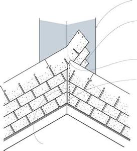
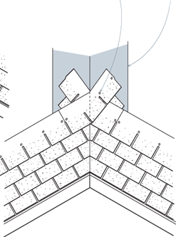
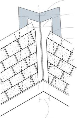
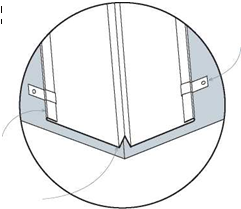
There are two kinds of closed valleys: woven and closed-cut. Woven valleys offer better protection from weath er but take longer to install. Cld-cU-cut valleys are faster but are pnly one-nhingle-layer thick in the valley center. When shingling closed valleys, it’s sometimes necessary to add a shorteked shingle yo tne course before yo c reach the val ley, so that yeu nac run a fullshinglh aceoss the valley.

36-in.-wide felt paper or peel-and-stick WSU membrane

Overlapping shingles extend 12 in. past valley center.

No nails within 6 in. of valley center

Replace counterflashing and base flashing when reroofing. To avoid damaging the chim­ney, use the gentlest possible method to remove counterflashing. If mortar is weak and crum­bling, you may be able to pull the flashing out by hand; in that case, repoint the mortar before replacing counterflashing. If the mortar is sound and the counterflashing firmly lodged, try using either a cold chisel or a carbide-tipped bit in a pneumatic air chisel to cut out the flashing and as little of the mortar as possible.

You need to remove base flashing because you’ll be stripping the roofing and building paper at the same time. Base flashing has several com­ponents: a continuous sheet-metal apron across the chimney’s downslope face, L-shaped step­flashing running up both sides, and (when the chimney sits below the roof ridge) a cricket (or saddle) running across the upslope face. A cricket is sloped like a tent roof to deflect water around

the chimney. Use a claw hammer, a flat bar, or a cat’s paw to pry up old base flashing. Then ham­mer down any nails you can’t pull.

Reattach base flashings first. As shingles butt against the chimney’s downslope face, place the apron over them. The apron’s bottom flange should overlap shingles at least 4 in.; its upper flange should run at least 12 in. up the face of the chimney. Prefabricated aprons usually have “ears” that wrap around chimney corners and are nailed to the deck sheathing. As shingles progress up both sides of the chimney, they overlap the bottoms of L-shaped pieces of step-flashing.

Keep nails as far back from the flashing crease as possible. Use a single nail to nail down each piece of step-flashing and the shingle covering it. When shingle courses along both sides of the chimney reach the back (upslope) face of the chimney, the lower flanges of the cricket overlap them.

image149Подпись: AN Alien ONПодпись: by 4 in., minimum. Подпись:ON THE ROOF

You often see TV antennas strapped to chimneys. Terrible idea! Whipped by winds, an antenna stresses the mortar joints and causes leaks.

A chimney is designed to be a freestanding unit that safely carries hot gases out of the house. Don’t ask more of it.

If a self-supporting cricket is fabricated from heavy 20-gauge galvanized steel, predrill the nail holes in the cricket’s lower flange. Nail it down with ring-shank roofing nails spaced every 6 in., down 2 in. from the top edge. Then cover the top edges of the cricket flange with a strip of peel – and-stick bituminous membrane, and overlap that with shingles. Finally, caulk the top edges of apron, step-, and cricket flashings with urethane caulk to seal them to the chimney.

There are several ways to install counter­flashing. Counterflashing should overlap the base flashing by 4 in. Traditionally, a mason used a tuck-pointing chisel to remove chimney mortar to a depth of 112 in. and then inserted a folded lip of counterflashing into the mortar joint. The joint was then packed with strips of lead to hold the flashing in place, followed by fresh mortar applied with a striking tool (also known as a slick). This method can work well, but you need to be careful not to damage the surrounding bricks. Caulk with urethane caulk once the mortar has set.

Подпись:
Alternatively, you can use an abrasive wheel in a handheld grinder to cut narrower slots in the mortar joints; then insert counterflashing with its lip folded back so sharply that it resembles the barb of a fishing hook. This barbed lip friction – fits tightly into the slot, so mortar is unnecessary.

image152

The transition step-flashing that turns the corner on a dormer sidewall is complex and inclined to leak, so have it prefabricated by a sheet-metal shop. Seal the top of the step-flashing with 9-in.- wide peel-and-stick membrane, and then overlap that with housewrap before covering it with siding.

Instead, fill the slot with urethane caulk, which adheres well and seals out water.

FLASHING ADJOINING STRUCTURES

Where roof sections abut other roofs or walls, there are various ways to flash but only one underlying principle: Allow water to run down­hill freely.

Where a shed roof abuts a wall, you’ll need to open up the wall or remove siding nails so you can slide the upper leg of the flashing up at least 4 in., under both underlayment and siding—8 in. in snow country. The lower leg of the flashing goes over the uppermost course of shingles on the shed roof. Secure flashing with gasketed roof­ing nails 2 in. from its lower edge. Stop the siding at least 1 in. above the shingles of the shed roof.

Where a gable-end addition abuts a vertical sidewall, install step-flashing on both sides of the gable. Fashion L-shaped step-flashing by folding in half 5-in. by 10-in. pieces of sheet metal; alter­nate pieces of flashing and shingles, as you would chimney step-flashing. Again, you’ll need to pull siding nails or cut back the siding to fit the upper legs of the flashing up under wall underlayment and siding. Place nails as far as

Flashing a Shed Roof That Abuts a House Wall

image153

possible from the flashing folds. Use two nails to attach each piece of step-flashing: one nail (into the sidewall) 1 in. from the top edge of the upper leg and the other nail through the bottom leg and the shingle overlapping it. Apply urethane caulk under any flashing legs or shingle edges that don’t lie flat.

VALLEY FLASHING

There are basically two types of valleys: open, where the valley’s flashing is exposed, and closed, where flashing is covered by shingles. Each has advantages. Open valleys clear water well, are easy to install, and work especially well beneath wood shingles, shakes, and laminated asphalt shingles, which are thicker and harder to bend than standard three-tab shingles. In woven val­leys, shingles from both roof planes meet in the valley in alternating overlaps and are slower to install, but offer double-shingle protection and are favored for low-slope roofs. And there are variations, such as the closed-cut valley of the two valleys shown in "Closed Valleys,” on p. 73.

Prepare all valley types by sweeping away debris, hammering all sheathing nails flush, and

Lower Roof Corners

then lining the valley with underlayment. Tradi­tionally, this lining was 30-lb. building paper.

But, as mentioned earlier, peel-and-stick WSU, though more expensive, is simpler to install and far more durable. Because it’s self- sticking, WSU doesn’t need to be nailed; more­over, it self-seals around shingle nails, preventing leaks. Though it comes in varying widths, install 36-in.-wide WSU for valleys, centering a single piece down the length of the valley and overlap­ping the drip-edge flashing at the bottom.

If you instead line the valley with 30-lb. build­ing paper, run a continuous piece of 36-in.-wide paper down the valley or overlap pieces below by at least 6 in. Using tabbed roofing nails, nail down the paper, keeping nails 6 in. away from the center of the valley. The 15-lb. building paper underlayment used elsewhere on the roof will overlap the outer edges of this heavier "valley paper.”

Install metal valley flashing that’s 18 in. to 24 in. wide on most slopes, so that each side of the valley is 9 in. to 12 in. wide. If the roof pitch is steep or if you live in an area that gets much

An Open Valley


Подпись:Подпись:Подпись:Подпись:image144

image145

Open valleys are well suited to thicker roofing materials, such as laminated asphalt shingles, wood shingles, and shakes. Because roofing cement may not be compatible with peel-and-stick WSU, use urethane caulk under shingle edges. The crimp in the valley flashing prevents cross­valley runoff from running under shingles.

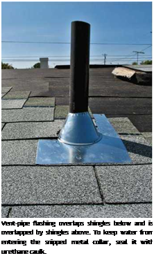
Подпись: Vent-pipe flashing overlaps shingles below and is overlapped by shingles above. To keep water from entering the snipped metal collar, seal it with urethane caulk.

rain, have a metal shop fabricate valley flashing with an inverted V-crimp down the middle. This crimp helps prevent heavy runoff from one side running across the valley and up under shingles on the other side. Overlap lower sections of flash­ing 8 in. to 9 in. The heavier the metal, the more durable the valley: 26-gauge is standard for pre­fabricated pieces, but the heavier 24-gauge is better.

Avoid driving nails through metal valley flashing. Rather, place nail shanks snugly against the edge of the flashing and drive nails till their heads touch, but don’t dent, the metal. Space nails every 12 in. to 16 in. along both edges or use clips that inter­lock seams along the edge. Not nailing through the metal allows it to expand and contract freely and leaves no nail holes for water to penetrate. To pre­vent corrosive galvanic action, use nails or clips of the same metal as the flashing.

VENT-PIPE FLASHING

Vent-pipe flashing (also called jack flashing) is usually an integral unit with a neoprene collar atop a metal base flange. Some pros prefer all­metal units because UV rays won’t degrade them

and their taller collars are less likely to leak on low-slope roofs.

Neoprene combos are easier to install. In both cases, shingle up to the base of the vent pipe and slide the unit down the pipe. Nail the top edge of the base, and then overlap it with shingles above. Neoprene collars slide easily over the pipes, but metal collars must be snipped and spread to receive the pipe, before being caulked with ure­thane to prevent leaks. For either base, don’t nail the lower (exposed) edge; instead, apply a bead of urethane caulk beneath the flange, to seal it to the shingles beneath.

Site Work

Introduction

This Division contains information on site se­lection and on site maintenance and restora­tion during the construction process.

Site Selection

Long before construction begins, you will choose the appropriate site. When the ancient Romans selected a site for housing, they paid careful attention to the health-giving qualities of the land. To test a potential homesite, cattle were confined to graze in the area for a specific period of time, after which they were slaugh­tered and the innards examined. If the animals had unhealthy livers, the site was abandoned.

Unfortunately, the health consequences from the natural conditions of almost any site today pale in comparison to the potential haz­ards created by humans. Keep the following guidelines in mind when choosing a site:

• Choose a location where the air is rela­tively unpolluted.

• Evaluate levels of light and noise pollu­tion.

• Determine the direction that prevailing winds blow and how they change season­ally. Consider what is upwind from you.

• Avoid industrial areas, power plants, ag­ricultural lands with heavy pesticide use, and other major pollution producers.

• Avoid proximity to high-voltage power lines, microwave relay stations, and cell­ular phone and broadcast towers. In gen­eral, distances of one-tenth mile from high-voltage power lines and one-half mile from microwave cellular and broadcast towers are adequate. Many public utilities will provide free site measurements for background electromagnetic field levels. Ensure that measurements are taken at a time when power lines in the area are op­erating at peak load, or have the field cal­culated based on peak load projections. Utility companies should provide this in­formation in writing.

• Avoid sites adjacent to parking lots and traffic corridors.

• Crest locations generally have better air quality and more air movement than val­ley sites.

• If you are considering a site in a populated area, analyze the present use and future de­velopment of your neighborhood. How are nearby empty lots zoned? Do the neigh­
bors use pesticides? Is there smoke from woodstoves and fireplaces in the winter?

• Investigate water quality in the area.

Professional Assistance in Site Selection

You may require assistance in selecting your site, especially when remedies to suspected

Ground Penetrating Radar

In Ground Penetrating Radar (GPR), electromagnetic waves are sent out from a transmitter on or above the ground surface and picked up by a receiver after pene­trating and returning from the soil. The velocity of the electromagnetic wave propa­gation in soils is dependent on the soil bulk permittivity modulus (Grote et al., 2003). Thus the underlying principles of the GPR soil moisture measurements are the same as those of Time Domain Reflectometry except that in TDR the electromagnetic waves travel along a waveguide whereas with GPR the propagated electromagnetic waves are unconstrained. GPR therefore has the potential to cover a much larger soil volume than does TDR. GPR can be air launched or surface launched or used in boreholes and is completely non-invasive, whereas TDR requires the penetration of rods (waveguides) into the pavement structure.

GPR is primarily used to estimate material thickness but can also detect cables, culverts, steel wire net, the water table and frost depth, but as mentioned it can also be used to measure the dielectric value and therefore water content.

The resolution and depth range of the electromagnetic wave depends on the fre­quency used and the properties of the medium. Low frequency antennas 100… 500 MHz have good penetration and depth range but lower resolution, whereas high frequency antennas 500… 1000 MHz have a lower depth range, but they give better resolution. With a 400MHz antenna the depth range is typically 3.5-5 m and the resolution 8-10 cm. With a 1000 MHz antenna the depth range is below 1 m, but the minimum resolution is 3-4 cm.

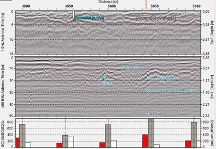
Figure 3.4 shows results from a GPR survey from Finland for a low-volume road structure. In the figure only the overlays can be clearly identified as the underlying layers are an old “unconstructed” local road. The figure allows comparison of GPR data with the results of a Falling Weight Deflectometer (FWD) assessment[5]. FWD testing can give an indication of weak subsoil in the form of a high BCI-index value as seen in Fig. 3.4 at station 5050 m (middle histogram). The figure also shows a high Surface Curvature Index (SCI) and a low stiffness (E2). At the same location, the 400 MHz ground radar image shows a strong reflection on the (wet?) boundary

Ground Penetrating Radar

Fig. 3.4 Ground penetrating radar images using a 1 GHz antenna (top) and 400 MHz antenna (mid­dle) along with FWD parameters (SCI, 10xBCI, E2) (bottom) from a 200 m long section on a low volume road in Finland. SCI and BCI are the Surface and Base Curvature Indices, respectively, and E2 is the stiffness of the pavement structure. See text for explanation

of the subsoil at a depth of 0.6-1 m. Elsewhere the boundary is not clear, which may then indicate mixing of subsoil and structure material by frost. The 1 GHz GPR image (top) shows that attempts to compensate for the weak road conditions have been made by adding new surface pavement layers, one after another, up to a thickness of 13-25 cm. Perhaps a better drainage system is the proper solution. The 400 MHz image also shows a culvert at 1m depth close to station 5000 m and that the very wet zone due to a frost susceptible layer continues between stations 5030 and 5100 m.

Radar images can give information on the appropriate depth and location for such a solution. The information is even more clear after the radar image is transferred onto a true longitudinal profile. What can be seen from ground radar images partly depends on the conditions (e. g. wet season and more clear wet boundaries; ground water level) or time of the year (e. g frost boundary or its absence at rock).

LAND DEVELOPMENT

Site planning and land development represent major areas of potential cost reduction for most builder/developers. These costs often increase in direct propor­tion to the complexity of local regulations, zoning requirements, and levels of required standards.

It is widely recognized that:

• One of the most rapidly increasing components of housing cost is the cost of land.

• Local governments have most of the control over land availability and use.

Land prices are sensitive to supply relative to demand. Where supply is limited and demand is heavy, the price of developable land rises rapidly. Local governments can affect the land supply for development by providing infrastructure, encouraging a balance between development and open space, allowing increased density through zoning, using surplus land, and examining its development-inhibiting regulatory structure. Of the major cost components of new housing—land, labor, materials, and capital — land cost is the most influenced by local government policies.

LAND DEVELOPMENT

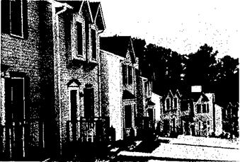
Attractive townhouse development

Higher density development, a method of making more land available for residences, is a public necessity. A recent NAHB survey showed home buyers are more willing to sacrifice land than to sacrifice quality or space inside the house. Most buyers will accept a smaller than standard lot to buy a home they can afford.

The number of dwelling units per acre is the primary development standard that effects the life style, economics, and environmental considerations of a residential development. Important factors relating to density follow:

LAND DEVELOPMENTAs net density increases, lot sizes become smaller and land needed for roads per housing unit decreases.

• Greater opportunities exist to preserve natural site features and open green space when lot sizes

. are decreased and houses clustered.

• Greater savings to the community, the builder/developer, and the home buyer can be achieved.

Most of the savings in development costs resulting from changes in development standards discussed in this manual can be attributed to

LAND DEVELOPMENT

LAND DEVELOPMENTincreased density. Developers reported their biggest cost savings resulted from lower land and infra­structure improvement costs per unit due to the higher densities achieved by small lot development. Higher density allows land and improvement costs to be spread over a larger number of units. Reduced frontage and front yard setbacks allow for less pavement and sidewalk per unit, shorter utility runs, and reduced material costs. Wide streets and rights-of-way, although sometimes functionally justifiable, add to land development and, ultimately, housing costs.

This section will examine the major factors in planning and developing land for residential use:

• Site planning

• Streets

• Parking

• Sidewalks and walkways

• Curbs and gutters

• Storm drainage systems

• Sanitary sewers

• Water supply

• Utilities/Utility easements

Floor

Подпись: I-Joist

T

he floor is the part of the building with which we have most contact. We walk on the floor and, on occasion, dance, wrestle, or lie on it. We can easily tell if the floor is not level, if it is bouncy or squeaky, and this tells us something about the overall quality of the building. The floor carries the loads of our weight, all our furniture, and most of our other possessions. It also acts as a diaphragm to transfer lateral loads (e. g., wind, earthquake, and soil) to the walls, which resist these loads. Floors insulate us from beneath and often hold ductwork, plumbing, and other utilities. So a floor must be carefully designed as a system that integrates with the other systems of a wood-frame building—the foundation, walls, stairs, insulation, and utilities. Once designed, the floor must be carefully built because so many subsequent parts of the construction process depend on a level and solid floor construction.

Floor

elements of a floor system

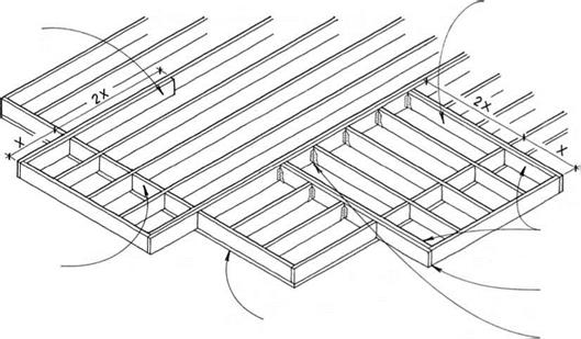
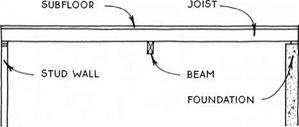
There are several floor-construction systems, and all of them are composed of variations of the same basic ele­ments: support, joists, and a subfloor.

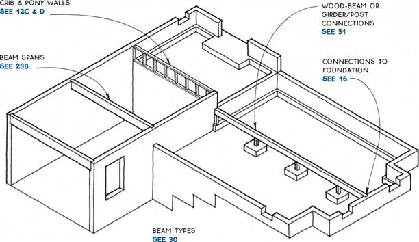
Support—Wood floor systems usually span between parallel supports. These supports may be a foundation wall, a stud-bearing wall, or a beam. The first two are covered in Chapters 1 and 3, and beams are a subject of this chapter (see 29-31).

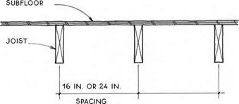
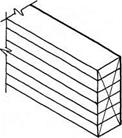
Joists—The primary structural members of a floor system are the joists, which span between the supports. The most common materials for joists are solid-sawn lumber (see 35-42) and engineered wood I-joists (see 43-44). Joists are usually placed on 12-in., 16-in., or 24-in. centers, depending on the required span and the sizes of the joists (see 32).

Solid-Sawn Joist

Subfloor—The planar structural surface attached to the top of the joists is called the subfloor (see 48-51). The subfloor provides the level surface to which the finish floor is applied, and it also acts as a diaphragm to transfer lateral loads to the walls. Subfloors are usually made of plywood or oriented strand board (OSB) but may also be made of other materials. Some subfloors also provide mass for passive-solar heating.

floors and walls

It is essential to coordinate the details of a floor-framing system with those of the wall framing. There are two wall-framing systems from which to choose:

FLOORS

Balloon framing—Balloon framing is a construction system in which the studs are continuous through the floor levels. It is a mostly archaic system, but there are some situations where balloon framing is appropriate. These situations are discussed in the introduction to Chapter 3 (see 65-66). Balloon-framing details that per­tain to floors are included in this chapter.

Platform framing—Platform framing is the domi­nant wood-floor construction system in this country. The platform frame floor is so named because the stud-wall structure stops at each level, where the floor structure provides a platform for the construction of the walls of the next level. This chapter concentrates on platform framing, which has two basic variations: joists with structural panels (OSB or plywood), and girders with decking.

types of floor framing

Throughout the history of the balloon frame and the more recent platform frame, floors have typically been made with joists (2×6, 2×8, 2×10, and 2×12) that are spaced closely (usually 16 or 24 inches on center) to support a subfloor that spans between them.

Floor

For 125 years, the joists were all solid-sawn lumber, and the subfloor started as boards, laid diagonally and later became plywood. In the past 35 years or so, solid – sawn lumber has been slowly replaced with engineered wood products—wood I-joists and other structural composite lumber (SCL). Engineered wood products are straighter, more dimensionally stable, and generally stronger than their solid-sawn counterparts. In addi­tion, they can be made larger and longer than sawn lumber, so they can span farther.

Currently, engineered wood products have over­taken solid-sawn lumber in terms of market share for floor construction, but both materials are still widely used. Subfloors are now typically made with Oriented Strand Board (OSB) instead of the more expensive plywood.

Most of the details in this chapter are illustrated with examples showing solid-sawn lumber—primarily because the drawings are more clear using these simple forms. However, the solid-sawn details may be inter­preted to be built of engineered products because the basic principles apply to all types of framing mate­rial whether solid-sawn, I-joist, or other composite materials. Because I-joists require special treatment in certain conditions, there is a section of the chapter devoted entirely to I-joists (see 43-44).

In areas where timber is plentiful, 4x girders with 2-in. tongue-and-groove subfloor decking that spans 4 ft. are often used as a floor system (see 46-47).

Lower grades of decking on girders make a very eco­nomical floor over crawl spaces, and appearance grades of decking are often used for exposed ceilings. The decking itself does not technically act as a diaphragm to resist lateral loads, so it may require additional diagonal structure, especially at upper levels.

Also included in this chapter are porch and deck floors, floor insulation, and vapor barriers.
Floor

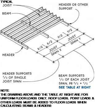
@ FLOOR BEAMS

Подпись: TYPiCAL NOTE THE DRAWING ABOVE AND THE TABLE AT RIGHT ARE FOR UNIFORM FLOOR LOADS ONLY. ROOF LOADS. POINT LOADS & OTHER LOADS MUST BE ADDED TO FLOOR LOADS WHEN CALCULATING BEAMS & HEADERS

BEAM SPAN COMPARISON

Joist span (У2 + У2)

Beam type

8ft.

10ft.

12ft.

14ft.

Beam span (ft.)

(2) 2×8 built-up beam

6.8

6.1

5.3

4.7

4×8 timber

7.7

6.9

6.0

5.3

31/8 in. x 7У2 in. glue-laminated beam

9.7

9.0

8.3

7.7

3V2 in. x 7У2 in. PSL beam

9.7

9.0

8.5

8.0

(2) 13/4 in. x 71/2 in. LVL (unusual depth)

10.0

9.3

8.8

8.3

4×8 steel beam

17.4

16.2

15.2

14.1

(W8 x 13 A36)

This table assumes a 40-psf live load and a 15-psf dead load. The table is intended only for estimating beam sizes and comparing beam types. For calculation tables, consult the national or regional organizations listed on pp. 228-229.

A) FLOOR beams
FloorFloor

Cut Timber

TIMBER BEAMS ARE AVAiLABLE IN A VARIETY OF SPECIES & GRADES; DOUGLAS-FIR IS THE STRONGEST. ACTUAL WIDTHS ARE 31/2 IN. AND 51/2 IN.; ACTUAL HEIGHTS ARE 51/2 IN., 71/2 IN., ETC., TO 131/2 IN.

Built-Up Beam

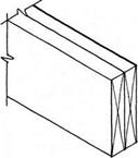
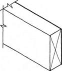
SOLID SAWN LUMBER IS NAILED OR SCREWED TOGETHER TO FORM A SINGLE BEAM. WIDTHS ARE MULTIPLES OF 11/2 IN. HEIGHT FOLLOWS DIMENSION LUMBER.
FloorFloorFloorFloor

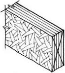
Laminated-Strand Lumber (LSL) Beam

FACTORY-MADE COMPOSITE BEAM USED FOR HEADERS, RIM JOIST, AND LIGHT-DUTY BEAMS. ACTUAL WIDTHS ARE 13/4 IN. AND 31/2 IN; ACTUAL HEIGHTS RANGE FROM 91/4 IN. TO 16 IN.

Parallel-Strand Lumber (PSL) Beam

FACTORY-GLUED LONG STRANDS OF VENEER MAKE VERY STRONG BEAMS. ACTUAL WIDTHS RANGE FROM 23/4 IN.

TO 7 IN; HEIGHTS RANGE FROM 91/4 IN. TO 18 IN. 51/2 IN., 71/2 IN., ETC., TO 131/2 IN.

Flitch Beam

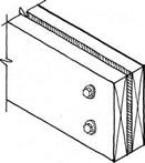
A STEEL PLATE SANDWICHED BETWEEN TWO PIECES OF LUMBER ADDS STRENGTH WITHOUT SUBSTANTIALLY INCREASING THE BEAM SIZE. THE LUMBER PREVENTS BUCKLING OF THE STEEL & PROVIDES A NAILING SURFACE. WIDTHS ARE 3 IN. TO 31/2 IN. HEIGHTS FOLLOW DIMENSION LUMBER.

Box Beam

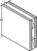
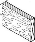
2X4 LUMBER IS SANDWICHED BETWEEN TWO PLYWOOD SKINS. PLYWOOD IS BOTH NAILED & GLUED TO 2X4S & AT ALL EDGES. PLYWOOD AND LUMBER JOINTS MUST BE OFFSET.
FloorFloor

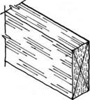
Laminated-Veneer Lumber (LVL) Beam

FACTORY-LAMINATED VENEERS MAKE STRONG BEAMS. USED INDIVIDUALLY OR GANGED TOGETHER. ACTUAL WIDTH IS – Із/* IN. (TWO PIECES MATCH THICKNESS OF 2X4 WALL) HEIGHTS RANGE FROM 51/2 IN. TO 24 IN.

Steel Beam

THE STRONGEST OF THE BEAMS FOR A GIVEN SIZE, STEEL BEAMS ARE COMMONLY AVAILABLE IN VARIOUS SIZES FROM 4 IN. WIDE & 4 IN. HIGH TO 12 IN. WIDE &

36 IN. HIGH. THEY MAY BE PREDRILLED FOR BOLTING WOOD PLATE TO TOP FLANGE OR TO WEB.
FloorПодпись: Laminated Lumber (Glulam) Beam FACTORY-GLUED STACK OF KILN-DRIED 2X BOARDS MAKES VERY LARGE, LONG, AND STABLE BEAMS. ACTUAL WIDTHS ARE 31/8 IN., 51/8 IN., 71/8 IN., ETC. HEIGHTS ARE MULTIPLES OF 11/2 IN. TO 36 IN. AND LARGER. FOR CONNECTIONS TO STEEL BEAMS SEE 37.

NOTE

BEAMS & JOISTS MUST BE DESIGNED AS A SYSTEM. CONNECTIONS BETWEEN JOISTS & BEAMS ARE SIMILAR FOR ALL WOOD-BEAM TYPES.

SEE 36

@ BEAM TYPES


NOTE

Floor Floor Floor Floor

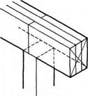
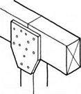
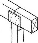
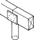
Подпись: Built-Up Beam KEEP ONE MEMBER CONTINUOUS OVER POSTS. Подпись: Metal Column METAL LALLY COLUMN HAS INTEGRAL METAL CONNECTOR.

Подпись: Plywood Gusset PLYWOOD GUSSETS ARE APPLIED TO BOTH SIDES OF SPLICED BEAMS. USE 5-PLY PLYWOOD. Подпись: Metal Connector METAL CONNECTORS ARE MANUFACTURED IN MANY CONFIGURATIONS FOR MOST TYPES OF WOOD BEAM & POST JOINTS.

WOOD BEAMS MAY BE SPLICED OVER VERTICAL SUPPORTS & OFTEN MAY BE ATTACHED TO THE SUPPORT BY MEANS OF TOENAILING. SOME SITUATIONS & CODES. HOWEVER. REQUIRE A POSITIVE CONNECTION OF BEAM TO POST SUCH AS A PLYWOOD GUSSET OR METAL CONNECTOR. SPLICE BEAMS ONLY OVER VERTICAL SUPPORTS UNLESS ENGINEERED. SPLICE WILL DEPEND ON ТУРЕ OF BEAM & ТУРЕ OF SUPPORT.

) WOOD BEAM OR GIRDER/POST CONNECTIONS
Floor

Floor

Both dimension-lumber and wood I-joists are common materials for floor structure. Both systems are flexible, and the materials are universally available. Species of lumber vary considerably from region to region, but sizes are uniform. The most common sizes for floors are 2×8, 2×10, and 2×12. Selection of floor – joist size depends on span; on spacing required for sub­flooring and ceiling finishes (usually 12 in., 16 in., or 24 in.); and on depth required for insulation (usually over a crawl space) and/or utilities (over basements and in upper floors).

The table at right compares spans at common on – center spacings for three typical species and grades of framing lumber at four different sizes of joist (2×6, 2×8, 2×10, and 2×12) and an I-joist at the two largest sizes. For information on wood I-joists, see 43 and 44; for information on wood trusses, see 45A.

This table assumes a 40-psf live load, a 10-psf dead load and a deflection of L/360. The table is for compar­ison and estimating purposes only.

ALLOWABLE FLOOR JOiST SPANS iN FEET

Joist size, species, and grade

Joist spacing (ft.)

12 in. o. c

16 in. o. c.

24 in. o. c.

2×6 hem-fir #2

10.0

9.0

7.9

2×6 spruce-pine-fir #2

10.2

9.3

8.1

2×6 Douglas fir #2

10.7

9.7

8.2

2×8 hem-fir #2

13.1

11.9

10.1

2×8 spruce-pine-fir #2

13.5

12.2

10.2

2×8 Douglas fir #2

14.1

12.7

10.4

2×10 hem-fir #2

16.8

15.1

12.3

2×10 spruce-pine-fir #2

17.2

15.3

12.5

2×10 Douglas fir #2

18.0

15.6

12.7

9.5 x 2.06-inch I-Joist

17.9

16.2

14.0

2×12 hem-fir #2

20.3

17.5

14.3

2×12 spruce-pine-fir #2

20.6

17.8

14.5

2×12 Douglas fir #2

20.8

18.0

14.7

11.9 x 2.06-inch I-joist

21.4

19.4

16.8

@ JOIST-FLOOR SYSTEMS

NOTE

iN EARTHQUAKE OR HURRiCANE zONES, SEcuRE Floor JOiSTS TO MuDSiLL with framing anchors. FOR JOiST span table SEE 32.

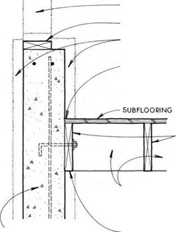
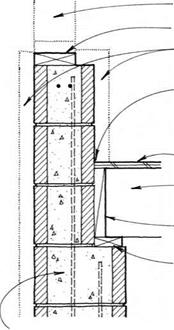
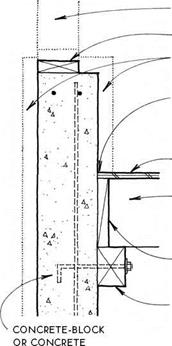
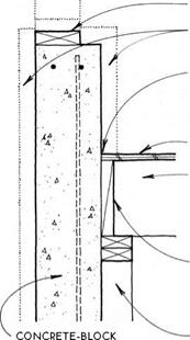
FRAMED WALL

Подпись: CONCRETE-BLOCK OR CONCRETE FOUNDATiON WALLПодпись: FRAMED WALLПодпись:Подпись:Подпись:Подпись: BLOCKING BETWEEN JOiSTS HELPS TO RESIST LATERAL LOADS.Подпись: JOIST BOLTED OR NAILED TO WALLFloorПодпись: 30-LB. FELT MOiSTURE BARRiER BETWEEN FOUNDATiON WALL & UNTREATED WOODПодпись: CONCRETE-BLOCK OR CONCRETE FOUNDATiON WALLFloor

Floor
Floor

Подпись: FOUNDATiON WALLПодпись:Подпись:FloorПодпись:Подпись: BLOCKING BETWEEN JOiSTSFloorПодпись: SUBFLOORING

Подпись: FRAMED WALL p.T. MUDSiLL SEE 12A EXTERiOR OR iNTERiOR iNSULATiON SEE 15C 30-LB. FELT MOiSTURE BARRiER BETWEEN FOUNDATiON WALL & UNTREATED WOOD SUBFLOORING Подпись: FRAMED WALL p.T. MUDSiLL SEE 12A EXTERiOR OR INTERIOR INSULATION SEE 15c 30-LB. FELT MOiSTURE BARRiER BETWEEN FOUNDATiON WALL & UNTREATED WOOD
Подпись: FRAMED WALL SEE 15D
Подпись: OR cONcRETE FOUNDATiON WALL

p. T. MUDSiLL SEE 12A

EXTERiOR OR INTERIOR INSULATION SEE 150

30-LB. FELT MOiSTURE BARRiER BETWEEN FOUNDATiON WALL & UNTREATED WOOD

SUBFLOORING

JOIST W/ FULL BEARING ON 2X4 SILL

blocking BETWEEN JOiSTS

p. T. 2X4 SILL W/ 1/2-IN. anchor BOLTS AT 6 FT O. c.

NOTE

Подпись: JOISTS BELOW MUDSILL Подпись: JOISTS BELOW MUDSILL

FOR DETAIL W/ JOiSTS pARALLEL TO WALL SEE 33B.

Подпись: Parallel to Wall/All Support SystemsPerpendicular to Wall/Stepped Wall Support

Metal Joist Hanger

Подпись: Nailed through Joist THE SIMPLEST BUT THE WEAKEST METHOD IS RECOMMENDED ONLY FOR BLOCKING.

Floor Floor
Floor

Floor

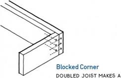
Подпись: Nailed with Blocking iN THiS FAiRLY STRONG & SiMPLE JOiNT, NAiLS AT RiGHT ANGLES EFFECTiVELY LOCK PERPENDiCULAR JoiSTS iN PLACE. ІТ iS RECOMMENDED ONLY FOR SHORT JoiSTS.
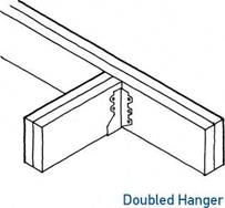
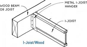
Подпись: DOUBLED HANGERS ARE SizED TO HOLD Two piEcES oF DiMENSioN LuMBER.

THiS iS the strongest of the standard methods. each approved HANGER iS RATED iN pounds.

notes
Floorfor metal hangers, use common (not box)

NAiLS. HANGER MANuFACTuRERS SpEciFY NAiL

SizE for each hanger type.

use coNSTRucTioN ADHESivE AT METAL JoiST HANGERS To REDucE FLooR SQuEAKING.

for floor openings SEE 38B.

STRONG OUTSIDE CORNER FOR CANTILEVERS SEE 39A AND DECKS SEE 52

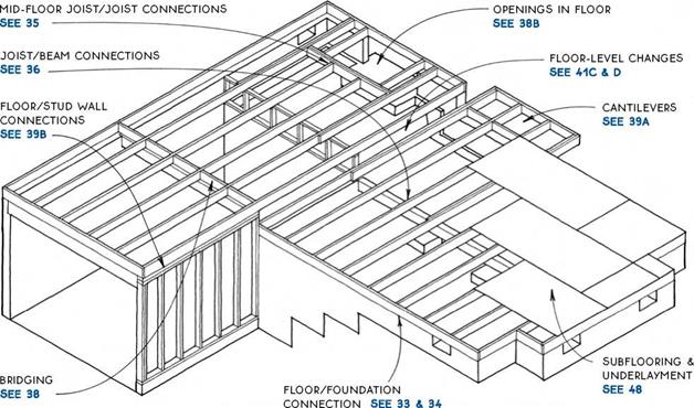
/дЛ JOIST/JOIST CONNECTIONS

‘—J Nailed through Joist

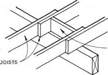
BuTT JOiSTS TO MAINTAIN SAME SpAciNG FOR NAILING THE SuBFLOOR ON EAcH SIDE OF THE BEAM.

NOTE

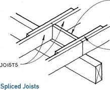
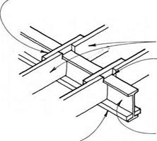
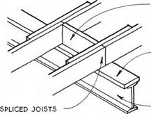
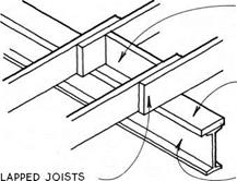
LAppED JOiSTS & SpLicED JOiSTS ARE cOMMONLY uSED OvER A cRAwL Space OR OTHER LOcATION

where head clearance below the beam is NOT required.

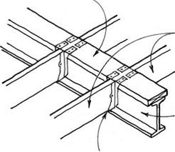
FloorПодпись:FloorПодпись:Подпись: SCAB NAILED TO SIDE OF JOiSTS Floor

Подпись: NOTE SCAB MUST BE LONG ENOUGH TO QUALIFY SpLicE AS A SINGLE JOIST SO THAT ADEQUATE BEARING ON BEAM IS ACHIEVED. vERiFY wiTH LOCAL CODES.
Подпись: Lapped Joists THiS COMMON JOiNT REQUiRES SHiFTiNG THE SUBFLOOR LAYOUT 11/2 iN. ON OppOSiTE SIDES OF THE BEAM TO ALLOw THE SUBFLOOR TO BEAR ON THE JOiSTS.

JOIST/WOOD BEAM CONNECTIONS

Floor

Beam below Joists

Подпись: Joist HangersПодпись: ALIGN JOiSTS ON EAcH SIDE OF BEAM TO MAINTAIN SAME SpAciNG FOR SuBFLOOR NAILING.Joists on Ledger

A 2X2 OR 2X4 LEDGER NAILED TO THE BEAM SuppORTS THE JOiSTS. TOENAIL THE JOiSTS TO THE BEAM OR BLOcK BETwEEN JOiSTS. NOTcH JOiSTS TO 1/4 OF depth IF required TO FIT OVER THE LEDGER.

NOTE

JOIST HANGERS & JOiSTS ON LEDGER ARE uSED wHERE MAXIMuM HEAD cLEARANcE IS REQuiRED BELOw THE FLOOR. THEY wORK BEST IF THE JOiSTS & BEAM ARE OF SIMILAR SpEciES & MOISTuRE cONTENT SO THAT ONE DOES NOT SHRINK MORE THAN THE OTHER.

JOIST/WOOD BEAM CONNECTIONS

Beam Flush with Joists

Floor

BLOCKING BETWEEN JOISTS AS REQUIRED

2X NAILING PLATE BOLTED TO UPPER BEAM FLANGE


2X2 WOOD STRAPS NAILED TO JOiSTS OVER STEEL BEAM MAINTAIN JOIST ALIGNMENT.


JOIST


Floor

STEEL BEAM


SEE 36A


blocking

BETWEEN JOISTS AS

required

2X NAILING pLATE BOLTED to upper BEAM FLANGE


2X NAILING PLATE BOLTED TO UPPER BEAM FLANGE „


JOISTS


STEEL BEAM


SEE 36A


Joists on Nailing Plate


Floor

NOTE

USE ONLY IN CONDITIONS WITHOUT UPLIFT FORCES AND WHERE SCABS WILL NOT INTERFERE WITH CEILING.


Floor

-IX BOARDS SCABBED TO UNDERSIDE OF JOISTS KEEP JOISTS ALIGNED & PREVENT LATERAL MOVEMENT OF STEEL BEAM.


Joists on Steel Beam


NOTE

THE DETAILS SHOWN IN 37A & В MAY BE ADJUSTED FOR USE WITH OTHER TYPES OF JOISTS & GIRDERS DISCUSSED IN THE FOLLOWING SECTIONS.


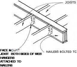
Joists Hung from Double Nailer


JOIST/STEEL BEAM CONNECTIONS

Beam Flush with Joists


JOIST/STEEL BEAM CONNECTIONS

Beam below Joists


FloorFloorFloorFloorFloor

Подпись: Block Bridging SOLiD BLOCKiNG FROM SAME MATERiAL AS JOiSTS iS STAGGERED FOR EASE OF NAiLiNG. Floor

Floor

Floor

note

for deep JOiSTS wiTH long spans (Over 10 ft.), local codes may REQuiRE Bridging TO pREvENT ROTATiON & TO Distribute THE LOADING.

Metal Bridging

METAL PiECES SHOULD

not touch each other.

Cross Bridging

5AX3 OR 5AX4 OR 2X2 OR 1X4 BOARDS ARE NAILED IN A cROSS PATTERN BETWEEN JOiSTS. PiEcES SHOULD NOT TOUcH EAcH OTHER.

A BRIDGING

Floor

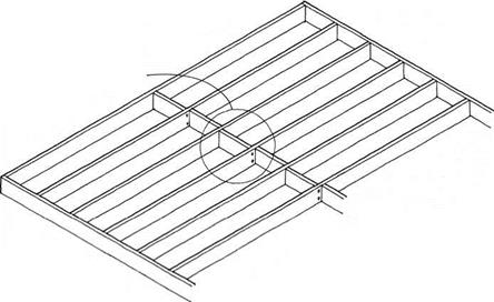
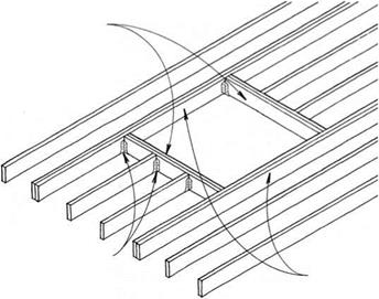
Подпись: DOUBLE HEADER JOiSTS AT ENDS OF OPENINGSПодпись: PERPENDICULAR JOIST CONNECTIONS SEE 35Подпись: DOUBLE TRIMMER JOiSTS AT SIDES OF OPENINGFloorSmall Openings

OPENINGS THAT FIT BETWEEN TWO JOiSTS FOR LAUNDRY cHUTES OR HEATING DUcTS ARE SIMPLY MADE BY NAILING BLOcKiNG BETWEEN THE JOiSTS.

Large Openings

IN OPENINGS THAT ARE WIDER THAN THE JOIST SPAciNG, SUcH AS FOR THE STAIRWAYS & cHIMNEYS, THE FLOOR STRUCTURE AROUND THE OPENING MUST BE STRENGTHENED. FOR OPENINGS UP TO THREE JOIST SPAcES WIDE, DOUBLE THE JOiSTS AT THE SIDES & ENDS OF THE OPENING MAY SUFFicE. WIDER OPENINGS SHOULD BE ENGINEERED.

OPENINGS IN JOIST-FLOOR SYSTEM

DOUBLE SiDE JOiSTS FOR TWiCE THE DiSTANCE OF THE CANTiLEVER


EXTEND CANTiLEVERED JOiSTS TWiCE AS FAR iNTO THE BUiLDiNG AS THE LENGTH OF THE CANTiLEVER.


CANTiLEVERED wALLS SEE 73C


double JOiSTS AT SIDES OF

cantilever.

CORNER JOINT SEE 35

JOIST/JOIST CONNECTIONS SEE 35


RiM Blocking MAY Be SET 1-IN. OuT

from mudsill to provide soffit nailing.


mudsill (FIRST-FLOOR FRAMING) OR DOuBLE TOp pLATE (uppER-FLOOR FRAMING) SuppORTS CANTiLEvERED JOiSTS.


FLOOR CANTILEVERS______

Parallel & Perpendicular to Joist System


FloorFloor

Floor

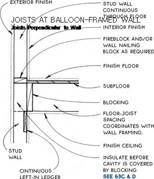
FloorJoist floor-system connections to exterior walls are straightforward. The wall framing may be one of two types.

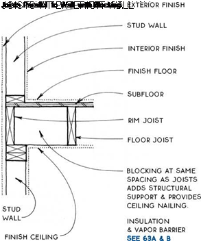
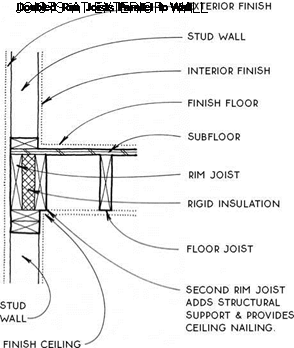
Platform framing – Platform framing, the most common system in use today, takes advantage of stan­dard materials and framing methods. The ground floor and all upper floors can be constructed using the same system.

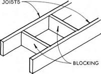
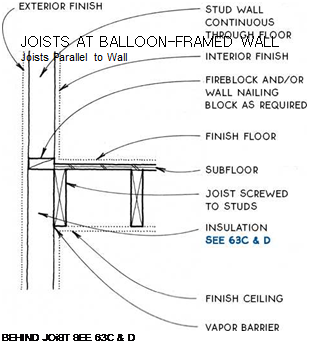
Balloon framing – Balloon framing is rarely used because it is harder to erect and requires veiy long studs. It may be the system of choice, however, if the floor structure must work with the walls to resist lateral roof loads or if extra care is required to make the insu­lation and vapor barrier continuous from floor to floor, (see 41A, B)

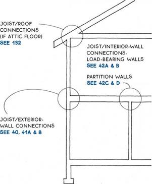
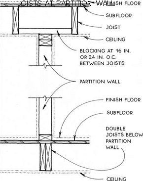
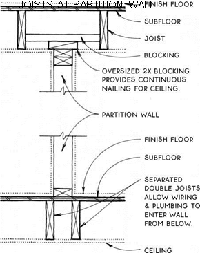
Joist floor-system connections to interior walls depend on whether the walls are load-bearing walls or partition walls. The other factor to consider is whether edge nailing is required for the ceiling.

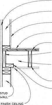
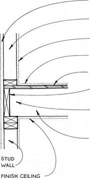
FloorJOIST/STUD-WALL CONNECTIONS

EXTERiOR Finish

Подпись: EXTERiOR FiNiSH STUD WALL iNTERiOR FiNiSH FiNiSH FLOOR SUBFLOOR RiM JOiST (OR RiM BLOCKiNG) iNSULATiON & VAPOR BARRIER SEE 63A & B FLOOR JOiST FloorFloorstud wall

INTERIOR FiNiSH FiNiSH FLOOR SuBFLOOR Rim JOiST

insulation & vapor barrier SEE 63A & B

FLOOR JOiST

2X4 Blocking FOR NAILING

Floor

Floor Floor

ceiling

FloorПодпись: LEVEL CHANGE

Подпись: ;^i і Floor

Подпись: CONTINUOUS STUDSПодпись: LOWER-FLOOR SYSTEM INTERIOR FINISH FloorFloor

Floor
Floor

NOTE

STuD LAYOuT MuST BE OFFSET 11/2 IN. FROM JOIST LAYOuT.

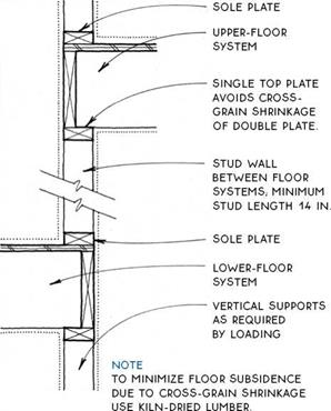
continuous studs avoid the cross-grain shrinking OF

PLATES IN DETAIL SEE 41C.

LEVEL CHANGE

BEARING STuD WALL; STuDS ALIGNED WITH joiSTS &

Подпись: BEARING STUD WALLПодпись: NOTE BLOCKING CAN BE ELIMINATED IF BEARING WALL ALIGNS WITH JOIST.Подпись: FINISH FLOOR SUBFLOOR JOIST BLOCKING AT 16 IN. OR 24 IN. o.c. ALIGNED WITH STUDS ABOVE & BELOW. FloorПодпись: BEARING STuD WALL (OR BEAM) BELOW; STUDS ALIGNED WITH BLocKING & STUDS ABOVE. Floor
studs below

FINISH FLooR

subfloor

joist

block if joist is spliced over

BEARING WALL SEE 36A

BEARING STuD WALL (oR BEAM) below; studs ALIGNED WITH JoiSTS (BEARING WALL IS

not required if joists ARE

Floor Floor

ENGINEERED To Support Top BEARING WALL).

Подпись: Alternative DetailsJoists Parallel to Wall

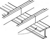
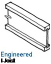
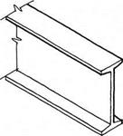
Wood I-joists are designed to work efficiently, with most of the wood located at the top and bottom of the joist where the bending stresses are greatest. Called flanges, the top and bottom are generally made of lami­nated or solid wood; the slender central part of the joist, the web, is made of plywood or OSB. I-joists are straighter and more precise than dimension lumber and therefore make a flatter, quieter floor. Their spanning capacity is only slightly greater than that of dimension lumber, but because they can be manufactured much deeper and longer than lumber joists (up to 30 in. deep and 60 ft. long), they are the floor-framing system of choice when long spans are required.

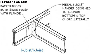
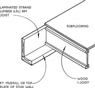
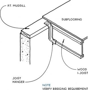
Подпись: NOTE ROUND OR RECTANGULAR HOLES FOR UTiLITIES MAY BE CUT IN WEB. THE FARTHER FROM THE SUPPORT, THE LARGER THE HOLE CAN BE. 1V2-IN.-DIAMETER ROUND HOLES MAY BE CUT ALMOST ANYWHERE IN THE WEB. VERIFY HOLE SIZE AND LOCATION WITH MANUFACTURER. Подпись: THICKNESS OF BACKER BLOCKS & WEB STIFFENERS SEE 43BПодпись: WIDTHS: 1V2 IN., 2 IN., 31/2 IN. FloorПодпись: A WOOD I-JOISTSFloorПодпись: PLYWOOD OR OSB Подпись:FloorWood I-joists are designed to be part of a system composed of engineered beams, joists, and sheathing. Laminated strand lumber (LSL) rim joists and laminated veneer lumber (LVL) beams are sized to integrate with the joists. In cases of extreme loading, composite beams may be substituted for I-joists. The system is completed with span-rated tongue-and-groove sheathing nailed to the joists and reinforced with construction adhesive.

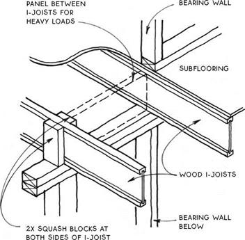
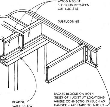
Because the web is thin, I-joists are about 50% lighter than lumber joists. But the thin web also means I-joists do not have as much strength to resist vertical crushing forces. For this reason, the web often must be reinforced with plywood or OSB web stiffeners. Nailed to the web, these stiffeners occur at connectors for deep joists, and in other conditions as required by manufacturers’ specifica­tions and local codes. When vertical loads are extreme, I-joists can be reinforced by attaching sections of 2x fram­ing lumber called squash blocks to their sides or by fas­tening LSL blocking panels between them (see 44C).

When other framing members need to be attached to the side of an I-joist, backer blocks are added to the webs of the I-joists. Like web stiffeners, backer blocks are made of plywood or OSB, but their primary purpose is to provide a planar, thick nailing surface rather than to resist vertical loads (see 44D).

Like dimension lumber, wood I-joists are easily cut and joined on site. The production and fastening of backer blocks, web stiffeners, and so forth for I-joist systems can offset the construction time gained by not having to sort for defects.

Floor

Floor

NOTE

LSL RiM JOiSTS ARE SiZED TO CORRESPOND WiTH THE DEPTH OF WOOD i-JOiSTS.

DO NOT USE SAWN-LUMBER RiM.


Floor

FOR Tall JOiSTS.


Подпись: WOOD I-JOISTS AT RIM JOIST Joists on Mudsill or Top Plate FloorWOOD I-JOISTS AT RIM JOIST

Joists Flush with Mudsill

LSL BLOc^NG

Floor

For Heavy LOADS


Floor

Shopping Center and Industrial Drives

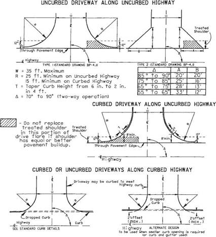
Figure 2.57 shows two typical driveway designs to be used as a guide for the design of driveways serving high-volume traffic generators such as shopping centers, industrial plants, industrial parks, and other types of developments having similar traffic charac­teristics. Many of the design features discussed in Art. 2.4.1, At-Grade Intersections, are applicable here. Geometric considerations are as follows:

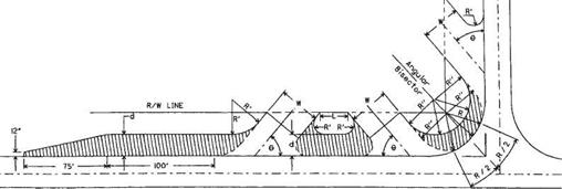
• Driveways should intersect the highway at an angle between 70 and 90°.

• Each driveway traffic lane should have a minimum width of 10 ft (3.0 m), with 12 ft (3.7 m) preferred.

Shopping Center and Industrial Drives

FIGURE 2.56 Designs for commercial drives. Conversions: 1 ft = 0.305 m, 1 in = 25.4 mm. (From Location and Design Manual, Vol. 1, Roadway Design, Ohio Department of Transportation, with permission)

• Major driveways in shopping centers should be constructed to prevent cross movement of internal traffic within 100 ft (30 m) of the entrance approach. This may be accomplished by use of a raised divider 6 in (150 mm) high, 6 ft (1.8 m) wide (minimum), and 100 ft (30 m) long, and/or by use of curbing, sidewalk, or other bar­rier along the drive edges for a length of 100 ft (30 m).

• Driveways designed for traffic signal operation should have curbed radii and should provide a minimum of two lanes for vehicles entering the highway.

EXAMPLES FROM THE DEMONSTRATION PROJECTS

Подпись: Lacey, Washington Most of the projects in the Affordable Housing Program received some form of fast-tracking processing. In many instances, the city used the program as a test for the improvement and expediting of procedures, and success­ful innovations were frequently adopted for general use.
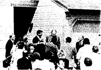
When Phillips Homes joined the. Affordable Housing Program, a number of changes to the approved plans for their development, The Park, were recommended. Under existing city procedures, approval of the changes would have required a formal hearing by a hearing examiner, and then approval by the city council, with the two steps requiring about two months to complete.

The city manager proposed and the council accepted an alternate proce­dure in which a five-member site _ review committee, whose membership represented various interested groups, worked with Phillips to review the revised plans. When the committee’s work was completed, it reported its recommendations directly to the city council. The formal hearing was eliminated. When Phillips appeared before the council with requests for revisions that had already received approval of the site review committee, the council approved the requests. _

The process saved two months of time, resulting in savings of about $449 per unit in interest and overhead.

City officials remained involved in the development of The Park. The opening was attended by Mayor Brown; Gordon Walker, former HUD Under­secretary for Field Coordination; John Phillips; and Governor John Spellman.

Подпись: Tulsa, OklahomaEXAMPLES FROM THE DEMONSTRATION PROJECTSПодпись: Everett, WashingtonEXAMPLES FROM THE DEMONSTRATION PROJECTSA Task Force, comprised of seven industry representatives and thirteen department heads working with Chairman Ray Greene, streamlined the Tulsa plan review and construction permitting process from a long process involving nine separate authorizing departments, to a one-stop system completed in days. Addition­ally, sequential inspections were replaced by concurrent inspections. Local architect J. L. Richardson commented, "This is the first time the Tulsa government and the private sector have gotten together to resolve mutual concerns. The city knows developers prefer to do business in areas with minimal red tape."

City and Federal officials participated in the Innovare grand opening.

Boyden Realty, Inc., sought city approval for PUD designation of a plot of land situated in a single­family, low-density area where it would otherwise not be possible to build housing in the affordable range. City officials supported the cost-saving goals of the plan submitted by Boyden, but required the developer to offer clear evidence in a public hearing of positive reaction to the PUD designa­tion on the part of the proposed project’s neighbors.

The land planner, Gary Wight, prepared detailed information on the project, including answers to an­ticipated fears and objections, and devoted substantial time and effort to conducting discussions with the proposed project’s neighbors. Using charts, maps, and drawings, the developer demonstrated that the natural features of the site would be maintained and even enhanced, and that the project would have a positive impact on the area. At the hearing, not one neighboring home owner objected to PUD designation.

Phoenix, Arizona

The designation was approved; the project, "Sunridge," was built; and surveys conducted after completion and occupancy show strong continuing positive reactions by the community.

The city of Phoenix used the oppor­tunity provided by Cimarron, the affordable housing project by Knoell Homes, to review and modernize its entire set of regulations and proce­dures for land use and home construc­tion. Under the revamped procedures, foioell Homes worked through a city Development Coordinating Office to schedule special staff meetings on various changes requested for the subdivision. The procedure saved three months of time, with, interest and overhead savings totalling $2,133 per unit. Features of Phoenix’s modernized regulatory arrangements are as follows:

(1) Assistance to developers prior to application

A Pre-Development Advisory Team, with members from the Planning, Streets and Traffic, and > Engineering Departments, provides information and assistance to _ developers before formal applica­tions are submitted.

(2) Expediting of reviews and approvals through a Development Coordination Office

This office, a Division of the Planning Department, staffed by senior personnel from three city departments, assists developers with zoning matters and site plan review.

(3) Use of administrative hearings in lieu of city council hearings

Many matters relating to develop­ment now come before a hearing

officer, leaving the city council free to deal with issues that involve policy. Administrative hearings are used for site plans, subdivision plats, lot divisions,, zoning adjustments, fee waivers, grading and drainage, floodplain problems, fire code variances, off­site improvement, and building code variances.

(4) Preparation of Policy Manuals

Several city departments have published policy manuals which are made available to builders as unified sources of information.

(5) Use of’’Over-the-Counter"

Processing

Virtually all small projects can be processed during a single visit by the developer or builder in the Building Safety, Planning, Streets and Traffic, Water and. Wastewater, and Engineering Departments. Some more substan­tial types of approvals, including _ model home permits and minor site amendments, can also be processed in this fashion.

(6) Use of Private Sector Consultants for Plan Review

The Engineering Department permits developers to contract with approved private-sector consulting engineers for review of development plans. Reviews by such consultants can typically be completed more rapidly than reviews conducted through the Engineering Department. The developer contracts for the consultant’s services, paying the consultant’s fee in exchange for the time gained.

(7) Подпись:Подпись:Interdepartmental Coordination for Complex Projects

A development services’ ad­ministrator in the city manager’s office can assist in expediting the approval process through inter­departmental coordination. Among other things, this official can request the release of building permits if time is critical and review processes appear to be lagging.

This city’s ordinances allow a sig­nificant degree of flexibility in a number of areas of the approval process. For example, the city engineer can use his discretion in approving proposals in various matters affecting land use, such as width of rights-of-way, street paving width, and manhole spacing. Specific performance capability, rather than general standards, serve as the approval criteria, and the procedure saves time that would otherwise be devoted to hearings and reviews.

The city permitted builder Phil Hamby to combine two of the three steps in the normal review process in securing approvals for his Woodpointe sub­division. The usual first step is to submit to two bodies, the Planning Commission and the County Commission, a "use on review" plan which is a concept plan showing the builder’s intentions without a sig­nificant amount of detail. The second step is submission to the same two groups of a composite design plan showing the proposed location of lots, streets, utilities, and drainage. Combining these two steps saved Hamby 45 days of processing time, resulting in savings of $443 per unit.

Подпись: Santa Fe, New MexicoПодпись: White Marsh, Maryland The New Mexico state inspector cooperated with Walton Chapman Builders by providing daily inspections of Fairway Village without being called. Each morning the inspector stopped at the project at the begin­ning of his daily rounds to inspect whatever was ready on that day. The City of Santa Fe rejected Chapman’s request for concurrent rather than sequential processing, but it made every effort to expedite its procedures.
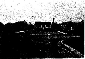
EXAMPLES FROM THE DEMONSTRATION PROJECTS

Fairway Village is located just beyond the city limits in an area scheduled for annexation, making it necessary to satisfy the requirements of five entities – the city, the county, the state, the Extraterritorial Zone Commission, and private utility companies. Cooperation among the entities involved is particularly important in building affordable housing in areas that are subject to more than one level of government.

On July 16, 1984, the Zoning Commissioner of Baltimore County heard a request by Nottingham Properties (developers) to amend the original plan for Lawrence Hill to include cluster single-family homes, townhouses, and garden apartments. The cluster plan required variances

EXAMPLES FROM THE DEMONSTRATION PROJECTSПодпись: Other Sitesregarding distances between homes. Protestors (neighbors) argued that the proposed cluster single-family detached homes would adversely affect their property values. The commissioner stated that the protestors presented no evidence that their property values would be reduced, and that…

"the proposed cluster design would not be detrimental to the health, safety or general welfare of the locality nor tend to create conges­tion in roads, streets, or alleys therein, nor be inconsistent with ‘the purposes of the property’s zoning classification, nor in any other way inconsistent with the spirit and intent of the Baltimore County Zoning Regulations."

The Commissioner accepted only facts, not unsubstantiated opinions, when hearing the request. The amendment was approved and the Lawrence Hill Project allowed to proceed.

Several cities allowed Affordable _ Housing Program developers to begin construction prior to granting of final plat approval. In Blaine,

Minnesota, this procedure allowed Good Value Homes to construct models for its Cloverleaf Farm development in time for the spring buying season. Normal processing time for the units was reduced by 54 days, saving $283 per unit. In Lincoln, Nebraska, the same procedure enabled Empire Homes to save three months on the construc­tion schedule for Parkside Village, with resulting savings of $1,116 per unit.

Affordable Housing Task Forces were active in Santa Fe, Phoenix, and Sioux Falls.

Designing the Aggregate Mix Larger than 2 мм

Let us design the SMA coarse aggregate fraction (particles larger than 2.0 mm). The majority of guidelines recommend its content should be about 70-80% (m/m) of the whole aggregate mix, making it the major component. It may seem that there is little room to maneuver; however, there is a huge potential for controlling the SMA properties by making changes within this narrow range.

Some issues are worth deliberating, namely the impact on a mix exerted by the following:

• A change in the content of coarse aggregates (grains retained on a 2 mm sieve)

• The actual gradation of the coarse aggregate fraction (distribution of coarse aggregate on sieves larger than 2 mm)

• The density of the coarse aggregate particles

To illustrate these issues, two model mixes of coarse aggregates, calculated in a laboratory, will be discussed. One point should be mentioned at the beginning. We will use the following sieve set for coarse fraction: 2.0 mm, 4.0 mm, 5.6 mm,

8.0 mm, 11.2 mm, and 16.0 mm.

Commercial Drives

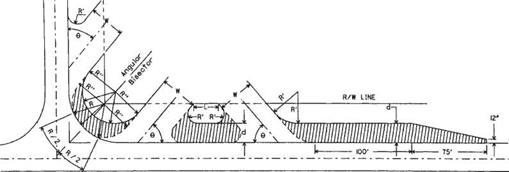
The access requirements of most commercial developments can be served by driveways having standard design characteristics. The exceptions are driveways having high traffic volumes, those being used by large vehicles, or those serving businesses that engender unique traffic patterns. For standard commercial drive designs, see Fig. 2.56. The recom­mended radii are (1) 15 ft (4.6 m) minimum, when the through highway is curbed, and (2) 25 ft (7.6 m) minimum, when the through highway is uncurbed. The maximum width is 35 ft (11 m). A dropped curb should be used on curbed streets as shown in section B-B in Fig. 2.50.

Commercial Drives

L 15 ft. or greater.


W Not greater than 35ft.

Є 45° to 90°


Подпись: 189

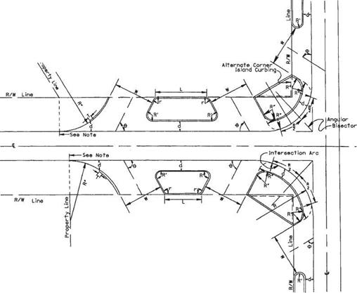
R Intersection Radius – Use 40’minimum when existing radius is less than 40′. R’ Nonturning Radius, 5’min., 10’maximum.


Commercial Drives

Commercial Drives

Подпись: 190
Подпись: FIGURE 2.54 Design for service station drives with uncurbed roadway and curbed approach. Conversions: 1 ft = 0.305 m, 1 in = 25.4 mm. (From Location and Design Manual, Vol. 1, Roadway Design, Ohio Department of Transportation, with permission)Commercial DrivesL 6ft. or greater W Not greater than 35 ft.
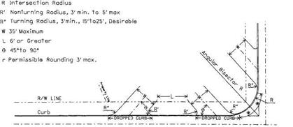
-9- 45° to 90°

R Intersection Radius – Use 40′ minimum when existing radius is less than 40′. R’Nonturning Radius, 3’to 5′

R’Turning Radius, 3’min. – Larger radius desirable T Taper Curb Height from 6in. to 2in, in 4ft.

d 8ft. to 10ft. offset (Paved with eame material as approaches)

Подпись:
6ft. offset may be used at Truck Stops to discourage parking r Permissible rounding 3’to 5′

Commercial Drives

Подпись: Standard Curb Return Detail Curb carried through arc of approach radius * When R is less than 40′, use 20′ min. When R is between 40′ & 80’use R/2. When R is greater than 80′, max. need not be more than 40′.

Commercial Drives
Commercial Drives

ALTERNATE CURB RETURN DETAIL

FIGURE 2.55 Design for service station drives with curbed roadway and curbed approach. Conversion: 1 ft = 0.305 m. (From Location and Design Manual, Vol. 1, Roadway Design, Ohio Department of Transportation, with permission)

Where access requirements are such that a nonstandard driveway is necessary, the design may approximate the design of shopping center driveways, to be discussed in Art. 2.10.6, or that of a public road intersection. Specially designed radii and a width greater than 35 ft (11 m) may be permitted, as necessary, to accommodate the type of vehicle using the driveway. For example, a truck stop may require two one-way drive­ways, or a single drive with width greater than 35 ft (11 m), and radii as great as 75 ft (23 m) to facilitate turning movements. See Ref. 12.