SIZING WITH THE UNIFORM PLUMBING CODE

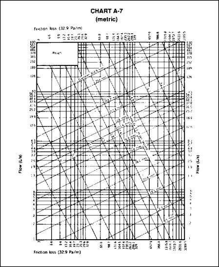
Sizing with data from the Uniform Plumbing Code is not too difficult. Allow me to give you some illustrations that are direct excerpts from the Uniform Plumbing Code. Look at the illustrations and try working through the sizing example that is provided (Fig. 3.1 through Fig. 3.17).

APPENDIX A


Because of the variable conditions encountered, it is impractical to lay down definite detailed rules of procedure for determining the sizes of water supply pipes in an appendix which must necessarily be limited in length. For a more adequate understanding of the problems involved, the reader is referred to Water-Distributing Systems for Buildings, Report BMS 79 of the National Bureau of Standards; and Plumbing Manual, Report BMS 66, also published by the National Bureau of Standards.

The following is a suggested order of procedure for sizing the water supply system.

A 1 Preliminary Information

A 1.1 Obtain the necessary information regarding the minimum daily service pressure in the area where the building is to be located.

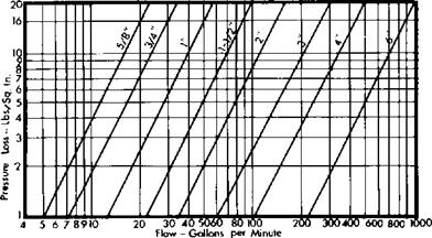
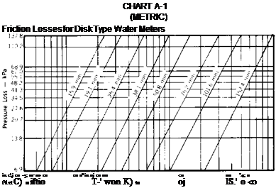
A 1.2 If the building supply is to be metered, obtain information regarding friction loss relative to the rate of flow for meters in the range of sizes likely to be used. Friction-loss data can be obtained from most manufacturers of water meters. Friction losses for disk type meters may be obtained from Chart A-1.

CHART A-1

Friction Losses for Disk Type Water Meters


SIZING WITH THE UNIFORM PLUMBING CODE

SIZING WITH THE UNIFORM PLUMBING CODE

A 1.3 Obtain all available local information regarding the use of different kinds of pipe with respect both to durability and to decrease in capacity with length of service in the particular water supply.

A 2 Demand Load

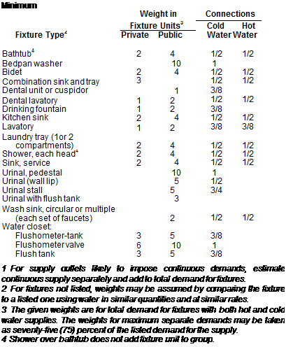
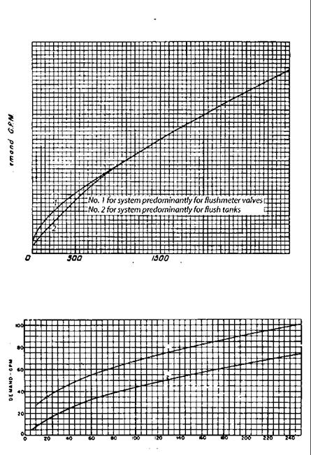
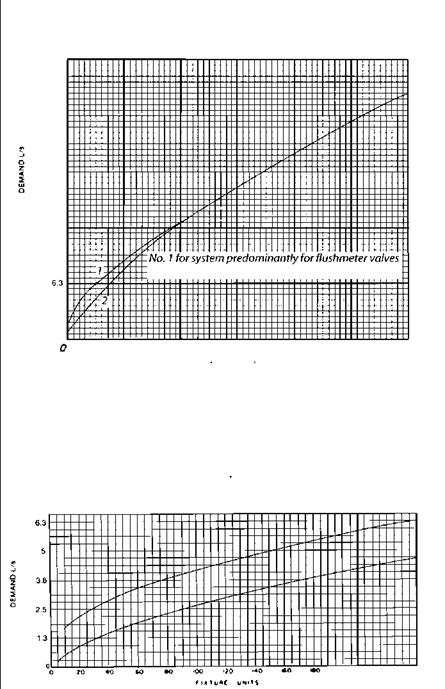
A 2.1 Estimate the supply demand for the building main and the principal branches and risers of the system by totaling the fixture units on each, Table A-2, and then by reading the corresponding ordinate from Chart A-2 or A-З, whichever is applicable.

A 2.2 Estimate continuous supply demands in gallons per minute (liters per second) for lawn sprinklers, air conditioners, etc., and add the sum to the total demand for fixtures. The result is the estimated supply demand of the building supply.

A 3 Permissible Friction Loss

A 3.1 Decide what is the desirable minimum pressure that should be maintained at the highest fixture in the supply system. If the highest group of fixtures contains flushometer valves, the pressure for the group should not be less than fifteen (15) psi (103.4kPa). For flush tank supplies, the available pressure may not be less than eight (8) psi (55.1 kPa).

A 3.2 Determine the elevation of the highest fixture or group of fixtures above the water (street) main. Multiply this difference in elevation by forty-three hundredths (0.43). The result is the loss in static pressure in psi (pounds per square inch) (kPa).


A 3.3 Subtract the sum of loss in static pressure and the pressure to be maintained at the highest fixture from the average minimum daily service pressure. The result will be the pressure available for friction loss in the supply pipes, if no water meter is used. If a meter is to be installed, the friction loss in the meter for the estimated maximum demand should also be subtracted from the service pressure to determine the pressure loss available for friction loss in the supply pipes.

TABLE A-2

Demand Weight of Fixtures in Fixture Units 1


SIZING WITH THE UNIFORM PLUMBING CODE

Diameter of fitting

90°

Stand­

ard

45°

Stand­

ard

Stand­

ard

Coupling

or

Straight

Gate

Globe

Angle

(inches)

Elbow

Elbow

Tee 90Run of Tee Valve

Valve

Valve

Feet

Feet

Feet

Feet

Feet

Feet

Feet

3/8

1

0.6

1.5

0.3

0.2

8

4

1/2

2

1.2

3

0.6

0.4

15

8

3/4

2.5

1.5

4

0.8

0.5

20

12

1

3

1.8

5

0.9

0.6

25

15

1-1/4

4

2.4

6

1.2

0.8

35

18

1-1/2

5

3

7

1.5

1

45

22

2

7

4

10

2

1.3

55

28

2-1/2

8

5

12

2.5

1.6

65

34

3

10

6

15

3

2

80

40

4

14

8

21

4

2.7

125

55

5

17

10

25

5

3.3

140

70

6

20

12

30

6

4

165

80


TABLE A-3

(metric)

Eauivalent Lenath of PiDe for Various Fittinas

90°

U1

0

Coupling

Diameter

Stand-

Stand-

Stand-

or

of fitting

ard

ard

ard

Straight

Gate

Globe

Angle

(inches)

Elbow

Elbow

Tee 90° Run of Tee Valve

Valve

Valve

m

m

m

m

m

m

m

9.5

0.3

0.2

0.5

0.1

0.1

2.4

1.2

12.7

0.6

0.4

0.9

0.2

0.1

4.6

2.4

19.1

0.8

0.5

1.2

0.2

0.2

6.1

3.6

25.4

0.9

0.5

1.5

0.3

0.2

7.6

4.6

31.8

1.2

0.7

1.8

0.4

0.2

10.6

5.5

38.1

1.5

0.9

2.1

0.5

0.3

13.7

6.7

50.8

2.1

1.2

3

0.6

0.4

16.7

8.5

63.5

2.4

1.5

3.6

0.8

0.5

19.8

10.3

76.2

3

1.8

4.6

0.9

0.6

24.3

12.2

101.6

4.3

2.4

6.4

1.2

0.8

38

16.7

127

5.2

3

7.6

1.5

1

42.6

21.3

152.4

6.1

3.6

9.1

1.8

1.2

50.2

24.3


* Allowances based on поп-recessed threaded fittings. Use one-half (1/2) the allowances for recessed threaded fittings or streamline solder fittings.


SIZING WITH THE UNIFORM PLUMBING CODE

A 3.4 Determine the developed length ot pipe from the water (street) main to the highest fixture. If close estimates are desired, compute with the aid of Table A-З the equivalent length of pipe for all fittings in the line from the water (street) main to the highest fixture and add the sum to the developed length. The pressure available for friction loss in pounds per square inch (kPa), divided by the developed lengths of pipe from the water (street) main to the highest fixture, times one hundred (100), will be the average permissible friction loss per one hundred (100) foot (30.4m) length of pipe.

A 4 Size of Building Supply

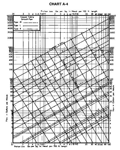
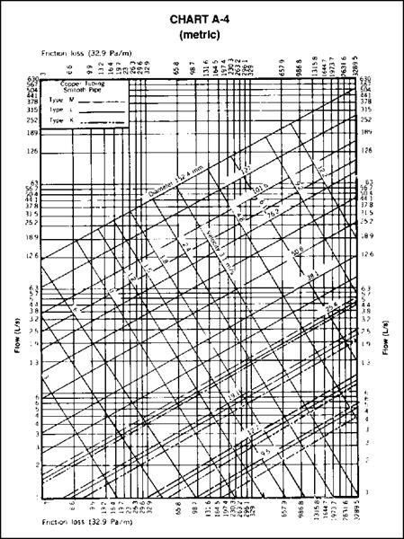
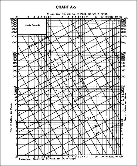
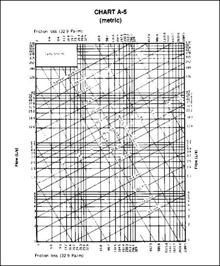
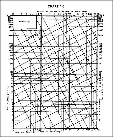
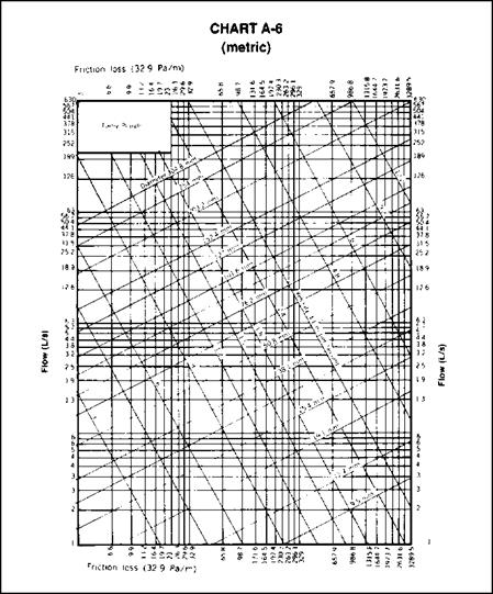
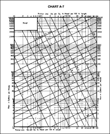
A 4.1 Knowing the permissible friction loss per one hundred (100 feet (30.4 m) of pipe and the total demand, the diameter of the building supply pipe may be obtained from Charts A-4, A-5, A-6, or A-7, whichever is applicable. The diameter of pipe on or next above the coordinate point corresponding to the estimated total demand and the permissible friction loss will be the size needed up to the first branch from the building supply pipe.

A 4.2 If copper tubing or brass pipe is to be used for the supply piping, and if the character of the water is such that only slight changes in the hydraulic characteristics may be expected, Chart A-4 may be used.

A 4.3 Chart A-5 should be used for ferrous pipe with only the most favorable water supply as regards corrosion and caking. If the water is hard or corrosive, Charts A-6 or A-7 will be applicable. For extremely hard water, it will be advisable to make additional allowances for the reduction of capacity of hot water lines in service.

A 5 Size of Principal Branches and Risers

A 5.1 The required size of branches and risers may be obtained in the same manner as the building supply by obtaining the demand load on each branch or riser and using the permissible friction loss computed in Section A 3.

A 5.2 Fixture branches to the building supply, if they are sized for the same permissible friction loss per one hundred (100) feet (30.4 m) of pipe as the branches and risers to the highest level in the building, may lead to inadequate water supply to the upper floor of a building. This may be controlled by: (1) selecting the sizes of pipe for the different branches so that the total friction loss in each lower branch is approximately equal to the total loss in the riser, including both friction loss and loss in static pressure; (2) throttling each such branch by means of a valve until the preceding balance is obtained; (3) increasing the size of the building supply and risers above the minimum required to meet the maximum permissible friction loss.

A 5.3 The size of branches and mains serving flushometer tanks shall be consistent with sizing procedures for flush tank water closets.


A 6 General

A 6.1 Velocities shall not exceed 10 ft/sec or the maximum values given in the appropriate Installation Standard, except as otherwise approved by the Administrative Authority.

A 6.2 If a pressure reducing valve is used in the building supply, the developed length of supply piping and the permissible friction loss should be computed from the building side of the valve.

A 6.3 The allowances in Table A-З for fittings are based on nonrecessed threaded fittings. For recessed threaded fittings and streamlined soldered fittings, one-half (1/2) the allowances given in the table will be ample.

A 7 Example

A 7.1 Assume an office building of four (4) stories and basement; pressure on the building side of the pressure reducing valve of fifty-five (55) psi (379 kPa) (after an allowance for reduced pressure "fall off” at peak demand); an elevation of highest fixture above the pressure reducing valve of forty-five (45) feet (13.7 m); a developed length of pipe from the pressure reducing valve to the most distant fixture of two hundred (200) feet (60.8 m); and fixtures to be installed with flush valves for water closets and stall urinals as follows:


Example


Fixture Units and Estimated Demands


SIZING WITH THE UNIFORM PLUMBING CODE

Water Closets

130

1,300

Urinals

30

150

Shower Heads

12

48

12

12×4 x

3/4 = 36 (2.3 L/s)

Lavatories

130

260

130

130×2 x

3/4 = 195 (12.3 Us)

Service Sinks

27

108

27

27×4 x

3/4 = 81 5.1 Us)

Total

1,866

313 (19.7 L/s)

312

106

(6.7 Us)

Allowing for fifteen (15) psi (103.4 kPa) at the highest fixture under the maximum demand of three hundred and ten (310) gallons per minute (19.6 L/s), the pressure available for friction loss is found by the following:


SIZING WITH THE UNIFORM PLUMBING CODE

55 – [15 + (45 x 0.43)] = 20.65 psi
(metric) 379 – [103.4 + (13.7 x 9.8)] = 142.3 kPa

The allowable friction loss per one hundred (100) feet (30.4 m) of pipe is therefore:

100 x 20.65 + 200 = 10.32 psi
(metric) 30.4 x 142.3 + 60.8 = 71.1 kPa

If the pipe material and water supply are such that Chart A-5 applies, the required diameter of the building supply is three (3) inches (76.2 mm), and the required diameter of the branch to the hot water heater is two (2) inches (50.8 mm).

The sizes of the various branches and risers may be determined in the same manner as the size of the building supply or the branch to the hot water system by estimating the demand for the riser or branch from Charts A-2 or A-З, and applying the total demand estimate from the branch, riser or section thereof, to the appropriate flow chart.


FIGURE 3.7 ■ Sizing rules. (Courtesy of The Uniform Plumbing Code)


CHART A-2


Estimate Curves for Demand Load


300


400


joo


б200


too


SIZING WITH THE UNIFORM PLUMBING CODE

гsoo jo oo


CHART A-3


Enlarged Scale Demand Load


FIXTURE UNITS


SIZING WITH THE UNIFORM PLUMBING CODE

SIZING WITH THE UNIFORM PLUMBING CODE

SIZING WITH THE UNIFORM PLUMBING CODE

Estimate Curves for Demand Load


31.5


35.2


18.9


12.5


No. 2 for system predominantly for flush tanks


300 /000 /300 2000 2300 3000


Fixture Units


SIZING WITH THE UNIFORM PLUMBING CODE

Enlarged Scale Demand Load


гoo г го г«о


FIGURE 3.9 ■ Friction loss tables. (Courtesy of The Uniform Plumbing Code)


SIZING WITH THE UNIFORM PLUMBING CODE

SIZING WITH THE UNIFORM PLUMBING CODE

SIZING WITH THE UNIFORM PLUMBING CODE

SIZING WITH THE UNIFORM PLUMBING CODE

SIZING WITH THE UNIFORM PLUMBING CODE

SIZING WITH THE UNIFORM PLUMBING CODE

SIZING WITH THE UNIFORM PLUMBING CODE

SIZING WITH THE UNIFORM PLUMBING CODE

SIZING WITH THE UNIFORM PLUMBING CODE

STAGE 3

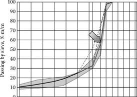
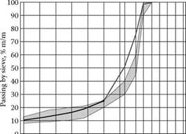
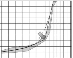
This time, let us add that 20% removed from 2/5.6 mm chippings to 8/11.2 mm chippings (that makes 25% + 20% = 45%), leaving the content of fraction 5.6/8 the same as in Stage I (25%). The composition of the new mix is shown in Table 6.8, while its gradation curve is shown in Figure 6.6.

The achieved mix falls between the upper and lower gradation limits. Obviously it still needs some refining within the sand fraction, but at the moment the main topic is the coarse aggregate. Perfectionists would say that a bit of "messing about" with the coarse fraction could be useful, by lowering the grada­tion curve even more on the 8 mm sieve, for example. But the question is, is it worth it?

After all, lowering the gradation curve on the 8 mm sieve will increase the share of particles larger than 8 mm, which means a more coarse gradation. The mix with a predominant share of the fraction 8/11.2 will make a strong skeleton; however, it will be characterized by a high value of voids in mineral aggregate (VMA) that requires a high binder content to achieve a suitably low content of air voids. We also obtain better (deeper) macrotexture, which means better skid resistance with high speed measurements. The down side is that such a mixture will have considerably higher permeability. So is this worth doing?

Despite this, let us make the last correction of the mix.

TABLE 6.8

Example of the SMA Mix with an Uneven Distribution of the Coarse aggregate Fraction among Three Fractions— predominantly chippings 8/11.2 (example II, stage 3)

Подпись:component of aggregate mixture content, (m/m)

Filler 10%

Crushed sand 0/2 15%

Coarse aggregate 2/5.6 mm 5%

Coarse aggregate 5.6/8 mm 25%

Coarse aggregate 8/11.2 mm 45%

Подпись: о d Подпись: CS ^0 ^ W Ln CO ‘ MH'I' - СЧ COПодпись: 10 20 30 40 50 60 70 80 90 100 Подпись: 0image480

Sieve, # mm

FIGuRE 6.6 Example of SMA mix with an uneven distribution of the coarse aggre­gate fraction among three fractions—the effect of the decrease in quantity of aggregate 2/5.6 and the supplement of 20% aggregate 8/11.2 (Example II, Stage 3).

Bending and Bending Failure

Yes, a good beam is a thing of beauty, but the main quality we are looking for in a beam is that it will not fail under the load we are asking it to carry. So we had better know a bit about the kinds of failures that can happen.

The failure in beams that people seem to grasp most easily is that of bending failure. If we keep loading a beam, particularly towards the middle of the span, we are placing ever greater bending stresses upon it. When we exceed the bending

Подпись: 2.5a Подпись: 2.5b strength of the beam, it will break, usually somewhere in the middle third of the span. This seems logical and natural, just as it seems natural that the two-by-eight plank described above is far more likely to break under a bending load if it is laid flat than if it is installed, properly, on edge. But common sense aside, it is useful to know why this is so from a structural or mathematical standpoint.

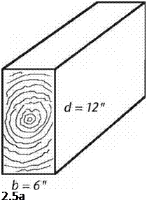
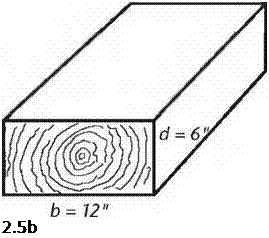
Because of a strength characteristic with the rather imposing name of section modulus, the depth (d) of the beam — the vertical dimension — has its value squared. But the breadth (b) of the beam carries only a regular linear value. For beams with rectilinear cross-sections, section modulus (S) is expressed: S = bd2/6. Interestingly, section modulus is solely a function of shape — geometry, if you like… and not a function of materials.

This strength relationship can be shown clearly if we look at the example of a timber with a 6-inch by 12-inch cross-section, because the constant — 6 — cancels out so conveniently. In Fig. 2.5a, we see a section of a six-by-twelve beam installed as it should be. The section modulus is the breadth (b, or 6") times the depth (d, or 12") squared, all divided by the constant 6. S = 6" X (12")2/6 = 144 inches cubed, the unit for section modulus (not to be confused with cubic inches.) On the bottom (Fig. 2.5b), the beam has been installed by a builder, who, to put it kindly, “is as thick as two short planks.” Now the breadth is 12 inches and the depth is 6 inches. So: S = 12" X (6")2/6 = 72 inches cubed. Now, mathematically, we can see that the beam is only half as strong in bending if we lay it down instead of standing it up correctly. I chose a six-by-twelve for easy math with whole numbers, but this relationship is true with any beam that is twice as deep as it is wide. With something like a two-by-ten joist, the difference is more extreme: the joist is five times stronger on bending installed “standing up” instead of “lying down.” The section modulus for a truly square beam or girder, like an eight-by-eight or ten-by-ten, can make use of the same formula, but as b and d are the same, it can be simplified to S = d5/6.

LOCATING CUTOUTS IN SHEATHING

LOCATING CUTOUTS IN SHEATHING

Подпись: You can use ring shank or hot- dipped galvanized nails when nailing off subfloor. These nails, along with the adhesive, will hold the sheathing to the joists and help prevent squeaky floors.

on my lower legs from breaking through subfloors while working on job sites decades ago. The sheathing panels we use today are much better than 1×6 boards—yet another improvement over how houses were built in “the good old days.”

Sheathing with 4×8 sheets of tongue-and – groove plywood or OSB is not difficult, though the sheets can be awkward to handle. Carry them with a partner, if necessary, and take care not to damage the tongues or the grooves, which can make it more difficult to fit the sheets together. Be sure to use exterior-grade, 5/s-in.- or 3/4-in.-thick sheathing.

Snap a line to lay out the first sheathing course

When laying out long rows of 4×8 sheathing, it’s best to start from a control, or reference, line. On one side of the building, measure in 48/4 in. at each end and snap a chalkline across the joists. The first row of sheathing is laid and nailed di­rectly on that line. Getting this first row straight makes it easier to lay all subsequent rows.

Lay down a full M-in. bead of construc­tion adhesive on the joists beneath each sheet just before setting it in place (see the photo on p. 71). This makes the floor structurally stronger and cuts down on squeaks in the future. Lay the first sheet with its grooved edge right along the

LOCATING CUTOUTS IN SHEATHING

Подпись: Cut sheets in place at the edge of the floor. With the circular saw's cutting depth set to the thickness of the sheathing, you can trim the excess from a panel directly on the rim joist.

control line, with one end on the center of a rim joist and the other end landing mid-joist—8 ft. to the left or the right. If a sheet doesn’t fall on the center of a joist, try pushing the joist over a bit. If this can’t be done, mark the sheet to length so the edge will land mid-joist, then snap a chalkline and cut the sheet. Finish sheathing the first row before moving on to the second one.

The second row of sheathing is installed much like the first, except that you begin with half a sheet (a 4-ft. by 4-ft. piece). This staggers
the joints, which makes for a stronger floor. If you’re building in a humid climate, leave about XA in. between the ends and the edges of the sheets to allow for expansion. This gap can be gauged by eye or by using an 8d nail as a spacer. The !/8-in. gap between sheets means that you will have to trim an end now and then so that each sheet lands squarely in the middle of a joist.

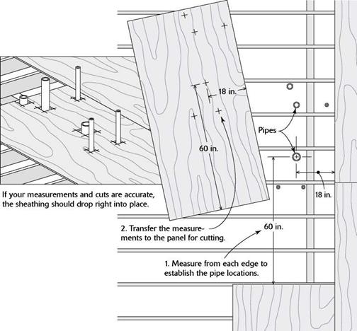
When plumbing pipes are installed before the sheathing, you must lay out and cut holes in the sheathing. The easiest way to lay out these cuts is to measure from the edges of sheathing already in place to the center of the pipe, then transfer those measurements to the sheet that the pipe will go through (see the illustration on p. 72). Cut the holes somewhat larger than the pipes, using a circular saw to make a plunge cut, as shown in Chapter 2. This makes it easier to lift the sheet and set it in place over the pipes. Later, seal the holes well to keep cold or moist air from entering the living space from below.

Secure the sheathing to the joists with 8d nails

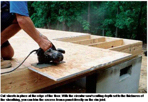
When the last panel in a course of sheathing extends beyond the rim joist, cut it flush with the rim joist before nailing it down (see the photo at left). The typical nailing schedule for sheathing is 8d nails 6 in. o. c. around the

ASPHALT SHINGLE REPAIR

Most roofs are repaired in response to leaks caused by a missing shingle or, more often, worn – out or missing flashing. Or, in some cases, it’s necessary to disturb shingles to install a roof vent or a plumbing vent.

When removing a shingle, or a course of shin­gles, disturb surrounding shingles as little as pos­sible. First break the adhesive seal between courses, by sliding a mason’s trowel or a shingle ripper (see the left photo on p. 121) under the shingles and gently slicing through the adhesive strips. It’s best to do this when shingles are cool and the adhesive is somewhat brittle and easier to break. If you attempt this when the roof is hot, you’re more likely to tear the shingles. However, actually working with the shingles—lifting them to remove nails or slide in new shingles—is best done when the shingle is warm and flexible.

To remove a damaged shingle, raise the shin­gles above and tear the old one out. If it doesn’t tear easily, use a utility knife to cut it out.

Remove the nails that held the damaged shingle by inserting a shingle ripper against the nail shafts and prying up. Keep in mind that those nails are actually going through two shingle courses—the one you’re trying to remove and the top of the course below. If you extricate the shin­gle and the nails don’t come up with a reasonable amount of trying, just knock them down with your hammer and a flat bar.

Fill old nail holes with roofing cement, and slide the new shingle into place. Gently lift the course above and position nails so they’ll be over­lapped by that course. Once you’ve inserted a new shingle, use the flat bar to help drive them down, placing the flat bar atop the nail head and striking the bar with a hammer.

Wood Shingles

There’s romance in wood shingles. Despite wood’s tendency to mold, grow moss, and catch fire and despite the diversity and durability of laminated asphalt shingles, wood remains popular.

Подпись:
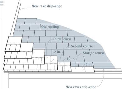
Подпись: New Roofing over Old Although "roofovers," placing new roofing over old, may be allowed by some codes, roofovers tend to be inferior. As noted earlier, you must strip a roof if there are two or more layers or if existing shingles are curling. That said, laminated shingles are usually better than three-tab shingles for roofovers because their random appearance hides minor irregularities in the old roof. Before beginning, replace or flash over old flashing as follows: ► Use aviation snips to cut away flashing around plumbing vents. ► Use a cold chisel to remove chimney counterflashing. ► Along the eaves, install a new drip-edge over the butt ends of existing shingles. ► Along the rakes, install a new J-channel drip-edge, which wraps around the old rake flashing and starter courses. ► Leave the old valley flashing in place, and install new over it. To level out an existing asphalt roof, rip down (reduce the height of) two courses of shingles, as shown in the drawing. Because asphalt shingles are routinely exposed 5 in., rip down the first strip (the starter course) so that it is 5 in. high. Then lay it over the original (old) first course so that the strip is flush against the butts of the original second course above. Next rip down a second strip (second course) 10 in. high and put it flush against the butts of the original third course. You now have a flat surface along the eaves. The third course of new shingles—and all subsequent shingles—need not be cut down, just butted to an original course above and nailed down. Use lVi-in. roofing nails for roofovers. PREPARING THE ROOF

Be sure to read the earlier sections on sheathing, underlayment, and flashing. And review the methods of asphalt-shingle installation, for they have much in common with wood shingling.

If the old roof was once covered with wood shingles, they were likely nailed to skip-sheathing, which consists of widely spaced 1-in. boards that allow air to circulate under the shingles and dry them. These days, most roofers cover skip­sheathing with plywood because it stiffens the roof and is safer to walk on. But nailing shingles directly to plywood or building paper impedes air circulation and may lead to cupping (shingles’ undersides will dry much more slowly than the tops), rotting, and shortened shingle life.

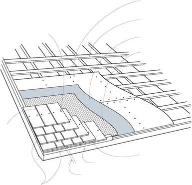
The answer to this dilemma is a layer of %-in.-thick synthetic mesh between the building paper and the shingles. CedarBreather is one brand, which comes in 39-in.-wide rolls. Roll the mesh out over 30-lb. building paper, tack or sta­ple it down, and you’re ready to shingle. The mesh retains enough loft to allow air to circulate freely around the shingles, so they can dry. To attach shingles over the mesh, you’ll need longer nails: 6d shingle nails should do, but check the product’s literature to be sure.

Flash a wood shingle roof as you would an asphalt roof, including WSU along the eaves, rakes, and valleys and metal drip-edge along the eaves and rakes.

ESTIMATING MATERIALS

Use only No. 1 (blue-label) shingles on roofs because they’re free of sapwood and knots.

Lesser grades are fine for siding but may leak on

image172Подпись: When installing a new roof over an old one, avoid a wavy-looking job by reducing the height of the first two courses to establish a flat surface.New Shingles over Old

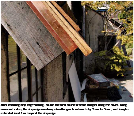
Подпись: After installing drip-edge flashing, double the first course of wood shingles along the eaves. Along eaves and rakes, the drip-edge overhangs sheathing or trim boards by ’/> in. to 3A in., and shingles extend at least 1 in. beyond the drip-edge. Подпись: Wood Shingle DetailsПодпись:Подпись: Two nails per shingle, in 3/4 in. from edgesПодпись:Подпись: Old skip-sheathingПодпись: Felt paperПодпись: Mesh allows shingles to breatheПодпись: 1/4-in. gap Подпись: Shingles overhang 1 in. at eaves and rake.Подпись:Подпись: Double first course of shingles along eaves.Подпись:image174"Подпись: BASICSa roof. Shingles come 16 in., 18 in., and 24 in. long, with recommended exposures of 5 in.,

5h in., and 7h in., respectively, on roofs with a

4- in-12 slope or steeper. Ultimately, slope deter­mines exposure and thus the number of bundles per square (100 sq. ft.).

In general, four bundles will cover a square.

To calculate the number of squares you’ll need, calculate the square footage of the roof and divide by 100. Because shingles are doubled along eaves and rakes, add an extra bundle for each 60 lin. ft. of eaves or rake. For valleys, add an extra bundle for each 25 lin. ft. For ridges and roof hips, buy preassembled ridge caps, sold in bundles that cover 16 lin. ft. One Canadian sup­plier, WoodRoof™ (www. woodroof. com) offers information about hip and ridge caps, precut "fancy butt” shingles, specialty tools, and more.

You’ll need 2 lb. of 4d or 5d galvanized shingle nails per square of shingles. For shingle caps along ridges and hips, use 6d shingle nails to accommodate the greater thickness of materials. Have your supplier deliver the materials in a lift – bed truck, so that you can unload the shingles right onto the roof.

INSTALLING WOOD SHINGLES

Double the first courses of shingles along the eaves, extending them beyond the drip-edge by 1 in.; and double shingles along rakes, overhang­ing rake trim by 1 in. In addition, install metal drip-edge along eaves and rakes. When nailing the bottom course of doubled shingles along the eaves, nail them about 1 in. up from the butt edges; if possible, sink the nails into the edge of the fascia board. Those two nails will be covered by the top course of doubled shingles. Nail that course with two nails placed 1 h in. above the exposure line.

wood Shingle i

No matter how wide the shingle, use only two nails—placed 3/ in. in from the edge, and 11/ in. above the exposure line. To allow for expansion, leave a 1/4-in. gap between shingles, unless they are wet, in which case you can place them snug against each other because they’ll shrink. Offset joints between successive courses at least 11/! in. Shingle joints that line up must be separated by two courses—in other words, shingle joints can line up every fourth course, but not sooner. Finally, nail heads should touch but not crush shingle surfaces; deeper, they may split the wood.

You could snap chalklines to indicate expo­sures for successive courses, but chalk can be unsightly and slow to fade. Instead, get a straight board as wide as the shingle exposure (5 in., for example), place its bottom edge flush to the bot­tom of the last shingle course, and position the next course of shingles by simply placing them atop the board. Move loose shingles around till all their joints are correctly offset to the courses below. Then nail them down.

When you start stretching to install courses above, install roof jacks as described on p. 81. Because wood shingles do not have fixed lengths as asphalt shingles do—just the same bottom line—several workers can work on a course at the same time. As you get within 6 ft. of the top, measure up to the ridge. If the ridge is not paral­lel to the eaves, there may be a discrepancy of several inches between measurements at one end of the roof and the other. If so, start adjusting exposures so that the final course of shingles will be more or less parallel to the ridge. If there’s a discrepancy of 2 in., for example, you should reduce exposures on the narrow end of the roof by ‘/a in. per course.

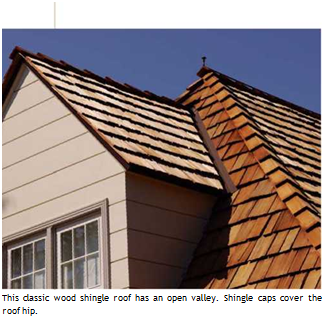
Open valleys. Refer to previous sections in this chapter on underlayment and valley flashing before you start. For most renovations, an open valley is the way to go: The exposed metal flash­ing of an open valley clears water well and is not likely to clog with debris and to dam up water. In addition, shingles running alongside an open val­ley require less fitting and cutting than those in closed valleys.

You can shingle out from a valley or into a val­ley from roof planes on either side. In either case, start by snapping parallel chalklines along both sides of the metal valley flashing, each line should be at least 3 in. from the center fold of the flash­ing. As each course approaches the valley, don’t nail the last four or five shingles immediately; just arrange them so that wide shingles end in the valley. Where shingles cross a chalkline, use a utility knife to notch the shingle at those points.

Keep nails as far as possible from the valley center: 5 in. away is minimum. A bead of ure­thane caulk under the leading shingles should keep the edges from lifting.

Closed valleys. Run shingles into the valley until they meet oncoming shingles from the other side. At that juncture, rough cut each shingle about 14 in. wide to establish the correct angle. Then use a block plane to back-bevel its leading edge. By cutting and planing, you create a compound angle so that the shingles fit tightly; this can be done only on the roof, shingle by shingle—a slow job. For best weathering, alternate miters right
and left, from course to course. Build up several courses in the valley and shingle out to the rest of the field.

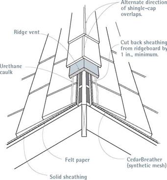
Ridge treatments. Be sure to read the com­ments on venting a ridge on p. 76. In brief, cut back sheathing at least 1 in. on either side of the ridgeboard. Then run underlayment and shingles to the edge of the sheathing before nailing a ridge vent over the opening.

► Shingle caps. Use a pneumatic nailer to attach preassembled shingle caps over the vent. Because the mesh underlayment and the ridge vent are compressible, they would move if you tried to hand nail them. Shoot 2-in. to 2/4- in. galvanized shingle nails through the shingle caps; nails should penetrate the roof sheathing at least /2 in.

► Ridgeboards. These butt to each other; for a weather-tight fit, they should be mitered. To establish the miter angle, lap two pieces of scrap at the peak and, using an adjustable bevel, transfer this angle to your table saw.

Подпись:Подпись: I Ventilating a Wood Shingle Ridgeimage175"Use a pneumatic nailer to attach preassembled ridge caps over the ridge vents because hand nailing the caps could split them.

Test-cut several pieces of scrap till the fit is tight; then rip down the ridgeboards on the table saw. Because ridgeboards should be as long as possible, get help nailing them down.

If it takes several boards to achieve the length of the ridge, bevel joints 60° and caulk each with urethane caulk.

Using 8d galvanized ring-shank roofing nails, nail the ridgeboards to the rafters; use two nails per rafter. Then go back and draw the beveled joint together by nailing it with 6d galvanized box nails spaced every 12 in. As you work, push down on the ridgeboards to force them together. To avoid splitting boards, predrill them or use a pneumatic nailer to shoot nails through the roofing layers into the rafters.

INTELLIGENT VEHICLE HIGHWAY SYSTEMS

Intelligent vehicle highway systems (IVHS) refers to transportation systems that involve integrated applications of advanced surveillance, communications, computer, display, and control process technologies, both in the vehicle and on the highway (Ref. 5).

In 1991, Congress passed the Intermodal Surface Transportation Efficiency Act (ISTEA), which included an authorization of $660 million to create an IVHS program for the nation. The goals for IVHS were defined as follows: to improve safety, to reduce congestion, to enhance mobility, to minimize environmental impact, to save energy, and to promote economic productivity. Research studies and demonstration projects to accomplish these goals are in progress. Funding has continued under subsequent legislation and experimental “smart highways” are being constructed.

The IVHS program is not limited to urban areas. It should result in benefits for both urban and rural drivers, and for both younger and older drivers. People who use public transportation will also benefit, and others will be persuaded to join them.

A planning process was undertaken following the adoption of the act, which identified 28 user services in six categories (Ref. 5):

Travel and traffic management

• Pretrip travel information

• En route driver information

• Traveler services information

• Route guidance

• Ride matching and reservation

• Incident management

• Travel demand management

• Traffic control

Public transportation management

• En route transit information

• Public transportation management

• Personalized public transit

• Public safety security

Electronic payment

• Electronic payment services

Commercial vehicle operations

• Commercial vehicle electronic clearance

• Automated roadside safety inspection

• Commercial vehicle administrative processes

• Onboard safety monitoring

• Commercial fleet management

• Hazardous material incident notification

Emergency management

• Emergency vehicle management

• Emergency notification and personal security

Advanced vehicle safety systems

• Longitudinal collision avoidance

• Lateral collision avoidance

• Intersection collision avoidance

• Vision enhancement for crash avoidance

• Safety readiness

• Precrash restraint deployment

• Automated vehicle operation

For those services listed under travel and traffic management, the emphasis will be upon providing real-time data to help the driver make the best decisions during a trip or even make last-minute changes in itinerary prior to departure. This category also encourages the use of high-occupancy vehicles and provides traffic control procedures and mechanisms to deal with situations as they occur.

The services under public transportation management will improve the efficiency, safety, and effectiveness of public transportation systems for users and providers alike. Again, the emphasis is on gathering and relaying real-time information to the users of the systems. It provides for automation of operations, planning, and manage­ment functions of public systems. It will also be able to monitor the environment in public station areas, including bus stops and parking lots, to generate alarms when necessary and increase public safety.

Electronic payment services will promote intermodal travel by providing a common electronic payment medium for all transportation modes and functions, including tolls, transit fares, and parking. One “smart card” could be used for several different modes of transportation.

Under commercial vehicle operations, trucks and buses equipped with transponders could have their safety status, credentials, and weight checked at mainline speeds. Vehicles passing the check would not have to pull over into the inspection/weigh facility. Automated safety inspections would allow “real-time” access at the roadside to the performance record of carriers, vehicles, and drivers. By using sensors and diagnostic equipment, vehicle systems and even driver alertness can be checked without stopping the vehicle.

Under emergency management, the capabilities of fleet management, route guidance, and signal priority can be used for emergency vehicles. Police, fire, and medical units can be directed over the most expeditious route to an incident site using real-time information. Driver and personal security systems will allow the user to initiate distress signals for incidents like mechanical breakdowns. Automatic collision notification would send information regarding location, nature, and severity of the incident to emergency personnel.

Concerning those services under advanced vehicle safety systems, a series of collision avoidance systems would be developed. For potential longitudinal, lateral, and intersection collisions, the systems would be able to sense impending trouble, warn the driver, and temporarily control the vehicle. On attempted lane changes, the driver’s blind spot would be monitored, and the vehicle prevented from making the switch if a vehicle was present. Another possibility is vision enhancement for the driver, in which the roadway and roadside are continuously scanned for potential hazards and the driver is made aware of situations when necessary. In-vehicle equipment can be used to monitor the driver’s condition and issue appropriate warnings. In employing precrash restraint deployment, the velocity, mass, and direction of the vehicles and objects involved in a potential crash are identified and the number, location, and physical characteristics of occupants are determined. This information in turn is used to trigger responses, such as tightening of lap-shoulder belts, arming and deploying air bags at optimal pressure, and deploying roll bars. Another program being investigated is automated vehicle operation. This would ultimately provide an accident-free environment on the roadway. Drivers would be able to buy a vehicle already equipped to drive under these conditions, or purchase instru­mentation and have it installed on an existing vehicle.

DRILLS

I remember making hole after hole with a hand-powered brace and bit in the early ’50s. I still have one hanging on the wall of my shop. Drilling bolt holes by hand in 2×6 sill plates was easy. But drilling a 1-in. bolt hole in a thick, solid beam took effort. Even with sharp bits, hand drilling was time-consuming. Today, a power drill fitted with the proper bit can drill the toughest hole in seconds. The power drill is a versatile tool. It makes holes in all sorts of mater­ial and can even be used for driving screws and for mixing paint and drywall compound.

DRILLS

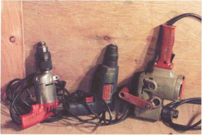
Every carpenter owns a power drill or two. Shown here are (from left to right) two 3/s-in. pistol-grip drills and a Уг-іп. right-angle drill.


Drill safety

• For clean, easy cuts, use sharp bits.

• Don’t force the drill. Let it cut at its own pace. When drilling into hard wood, coat the bit with wax or soap to make drilling easier. Use low speeds for drilling into steel and lubricate the bit with oil to re­duce friction and heat buildup.

• Treat any drill with respect, just as you would a cir­cular saw. Drills have a lot of torque (turning power). If a bit gets hung up on a hard knot or a nail, all the power of the drill is transferred to its handle, which will give your arm a powerful (and potentially wrist­breaking) twist.

• When drilling into heavy or thick material, use two hands to hold the drill steady. When drilling with an auger bit or with a powerful drill, use the side han­dle. The torque can be so great that it is hard to hold these tools with one hand.

• Work with your feet apart and your body in a well – balanced position. Be especially careful when drilling from a ladder. Make sure the ladder is stable and that you are not in an awkward position.

• Make sure what you are drilling is secure. If it is not stationary, clamp the workpiece to a sawhorse or to a workbench. Don’t try to hold the piece to be drilled with your hands. It’s too easy to lose control of the piece and injure yourself.

There are three basic things you should consider when buying a drill: its size, type, and chuck style. Drill sizes are dic­tated by the largest bit shank (the shaft of the bit) that will fit into the chuck (the jaws that hold bits). Common drill sizes are 1/4 in., 3/s in., and 1/2 in., and most carpenters own both 3/s-in. and У2-ІП. drills. My3/s-in. drill is reversible (mean­ing I can change the direction the bit rotates) and has a variable-speed switch. These two qualities allow me to use the drill for both driving and removing screws. Even better, when a bit gets stuck, I can switch to reverse and back it out of the hole. I use my powerful Уг-іп. drill when I need to drill larger holes (for example, for bolts or locksets). A handy accessory for а Уг-іп. drill is a side han­dle, which allows you to hold the drill securely with two hands when drilling large holes.

There are different types of drills. Some have a pistol grip, while others have two handles. Some drill straight on, while others drill at a right angle (see the photo on the facing page). The type of drill you need depends on the work you do.

I use my Уг-іп. right-angle drill in tight places (for example, in stud and joist bays) and hold on tight when I’m using it. This tool has a lot of power. The hammer drill is a variation of the stan­dard drill. This tool moves a drill bit in a circular and up and down motion at the same time. You can drill through concrete or other masonry materials like magic.

Although many drills have chucks that are tightened around a bit’s shank using a key, most carpenters now prefer drills with keyless chucks. That means the chuck is tightened by hand. Keyless chucks are fine for most work and allow for quick bit changing. But for heavy – duty drilling, you’ll still need a keyed chuck to keep the bit from slipping.

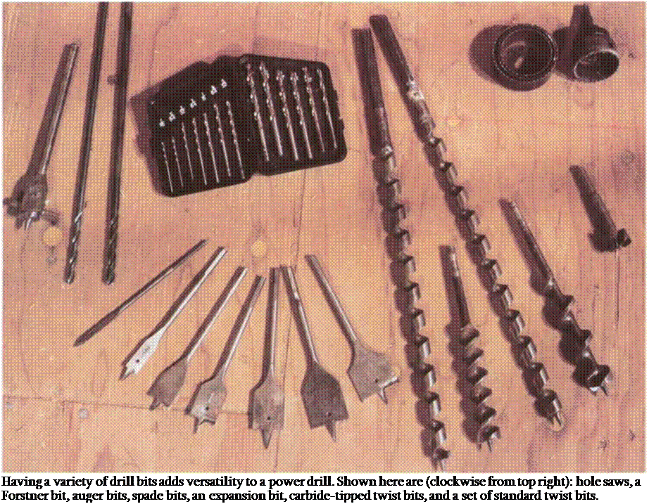
Подпись: Having a variety of drill bits adds versatility to a power drill. Shown here are (clockwise from top right): hole saws, a Forstner bit, auger bits, spade bits, an expansion bit, carbide-tipped twist bits, and a set of standard twist bits.
Bits

In general, buying drill bits in sets is less expensive than buying them individually.

I use standard twist bits (from Vm in. to Vi in.) to drill holes in wood, and hard­ened or carbide-tipped bits to drill holes in metal, masonry, tile, and glass.

bottoms, smooth sides, and a clean top edge that can later be filled with a wood plug.

Holes for door locksets (which are typi­cally 2[3]/s in. dia.) can be drilled with a hole saw. Available in sizes ranging up to 6 in., hole saws (which are bits that have teeth around the perimeter like a saw) can have bimetal teeth for cutting large holes, not only in wood but also in light metals, plastics, and fiberglass.

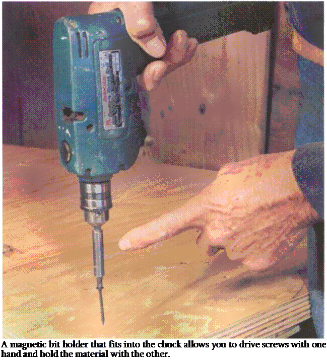
Подпись: A magnetic bit holder that fits into the chuck allows you to drive screws with one hand and hold the material with the other.
Auger bits are handy for cutting holes through thick material, such as бхб beams. They are self-feeding, meaning that they pull themselves into the hole, and don’t require a lot of force on the part of the drill operator. Adjustable expansion bits can cut holes of varying size.

For finish work, it’s often a good idea to countersink screws (putting the screw head below the finish surface) using a countersink bit. This type of bit has a
beveled face that makes the screw hole larger at the top to fit the head of a wood screw.

For driving screws, every carpenter car­ries different screwdriver bits. While you’ll still occasionally come up against a slotted screw, most screws on a con­struction site have a Phillips head. This configuration keeps the bit centered on the screw and provides better purchase, perfect for setting screws with a drill or screw gun. A useful accessory for driving screws is a magnetic bit holder, which

fits into the drill chuck to hold screw­driver bits (see the photo on p. 53). This setup makes it easier to drive screws with one hand and change bits quickly.

Part II: Gradation within the Coarse Aggregate Fraction

When designing the shape of a gradation curve in the coarse aggregate fraction (larger than 2 mm), it is worthwhile to pay attention not only to the percentage of grains larger than 2 mm (retained on a 2 mm sieve) but also to the ratios of contents of various coarse aggregate fractions. According to many recommendations (i. e.,

Schroeder and Kluge, 1992; Voskuilen, 2000), mixtures characterized by a certain deficiency of smaller coarse aggregates, or even a lack of them, should be preferred. So, let us proceed to Example II to discuss changes in the gradation within the coarse aggregates’ fraction. This example is not complicated, therefore we will not encounter any difficulties in its interpretation; this is especially for anyone who often designs using the gradation limits method.

Example ii: Changes in Gradation within the Coarse Aggregate Fraction

Let us start analyzing an SMA mixture that has fixed contents of particles larger than 2 mm at 75% (m/m), filler at 10%, and fine aggregate at 15%. The grada­tion curves of SMA 0/11 according to ZW-SMA-2001, fine aggregate 0/2, a filler, and 3 fractions of the coarse aggregate (2/5.6, 5.6/8, and 8/11.2) will be used for the analysis. To make the task easier, an assumption has been made that none of the aggregate fractions has any undersized or oversized particles. All percentage values of this example apply to percentage by mass (i. e., mass fraction [m/m]).

stage 1

Briefly, should equal shares of each of the coarse aggregate fractions—2/5.6, 5.6/8 and 8/11.2—be secured, the mixture presented in Table 6.6 is the result.

Even though the coarse aggregate fraction totals 75% (m/m) of the mixture and everything seems to be all right with regard to its content, the desired discontinu­ity of gradation is impossible to achieve by the use of this uniform distribution of constituents (at 25% each) (Figure 6.4). We can even safely say that there is a kind of continuity of gradation within the coarse aggregate fraction.

stage 2

Now let us divide the coarse aggregate fraction into other proportions. According to the conclusions of Example I, more coarse aggregate have to be added but material 2/5.6 mm has to be removed to break the gradation curve and pull it down at the 5.6 mm sieve. In Example II, Stage 1, 25% of the coarse particles pass through the 2-mm sieve (the fixed quantity, as assumed) and 50% through the 5.6-mm sieve (Figure 6.4). The expected level of particles larger than

TABLE 6.6

Example of the sMA Mixture with a uniform Distribution of the coarse Aggregate Fraction among Three Fractions (Example ii, stage 1)

component of an Aggregate mixture

content, (m/m)

comments

Filler

10%

Aggregates for mastic

Crushed sand 0/2

15%

Coarse aggregate 2/5.6 mm

25%

Coarse aggregate >2 mm

Coarse aggregate 5.6/8 mm

25%

(total 75% [m/m])

Coarse aggregate 8/11.2 mm

25%

5.6 mm exceeds 50% (e. g., 70% [passing through the sieve 5.6 mm at 30%]). The result is that the increase in material between sieves 2 and 5.6 (passing at 25% and 30%, respectively) should amount to approximately 5%, which is tantamount to the statement that screening of the fraction 2/5.6 mm in the given aggregate mix should be approximately 5%. Screening of the fraction 2/5.6 mm here is identical with the aggregate 2/5.6 mm. Therefore chippings of 2/5.6 mm have been reduced from 25 to 5%.

The only thing remaining is to decide where to add the regained 20% of the coarse aggregate—to chippings of 5.6/8 or to 8/11.2 mm?

Let us suppose that the regained 20% is being added to 5.6/8 mm chippings, leaving the fraction 8/11.2 unchanged. Table 6.7 presents the mix composition at that stage, while Figure 6.5 illustrates its gradation curve. It should be remembered that the share of material larger than 2 mm remains unchanged and still amounts to 75% (m/m).

Подпись:Подпись:Подпись:Подпись:Подпись:image460

10

20

30

40

50

60

70

80

90

100

FIGURE 6.4 Example of an SMA mixture with an even distribution of the coarse aggregate fraction among three fractions (Example II, Stage 1).

TABLE 6.7

Example of the SMA Mix with an Uneven Distribution of the Coarse aggregate Fraction among Three Fractions— predominantly aggregates 5.6/8 (example ii, stage 2)

Подпись: component of aggregate mixture Filler Crushed sand 0/2 Coarse aggregate 2/5.6 mm Coarse aggregate 5.6/8 mm Coarse aggregate 8/11.2 mm content, (m/m) comments

10% Aggregates for mastic

15%

5% Coarse aggregate >2 mm

45% (total 75% [m/m])

25%

Подпись: 90 80 70 60 50 40 30 20 10 0 image47 Подпись: CO 40 40 VO CN CN c—і ,—і ^
Подпись: и Part II: Gradation within the Coarse Aggregate Fraction

Sieve, # mm

FIGURE 6.5 Example of SMA mix with an uneven distribution of the coarse aggre­gate fraction among three fractions—the effect of a decrease in quantity of aggregate 2/5.6 and the supplement of 20% chippings 5.6/8 (Example II, Stage 2).

A better gap-gradation is a distinctive feature of the achieved gradation curve. The broken shape of the gradation curve of that mix is clearly noticeable. Despite that improvement, the mix is still not acceptable because there is too little material larger than 8 mm. So replacing the 20% chippings 2/5.6 removed with only chip­pings 5.6/8 has not led to the defined goal. Therefore let us try another variant.

Using Pneumatic Nailers

Because pneumatic nailers can easily blow nails through shingles, some codes specify hand nailing. And it’s safer to hand nail the first five or six courses along the eaves, where stepping on a pneumatic hose could roll you right off the roof. Wear goggles when using nailers. Those concerns aside, pneumatic nailers are great tools if used correctly. Here’s how:

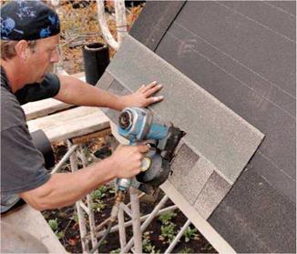
► Don’t bounce-fire a nailer till you’re skilled with it. (To bounce- fire, you hold the trigger down and press the nailer’s nose to the roof to fire the nail.) Shingles must be nailed within a small zone—below the sealer strip but above the cutouts, if any—and it’s hard to hit that zone if the nailer is bouncing around. Instead, position the nailer nose where you want it, and then pull the trigger.

► Trigger-fire the first nail of every shingle. Do this to keep shin­gles from slipping, even if you’re skilled with pneumatic nailers. Once the first nail is in, you can bounce-fire the remaining ones.

► Hold the nailer perpendicular to the roof so nails go in straight, and keep an eye on nail depth as the day wears on. Nail heads should be flush to the shingle; if they’re underdriven or overdriven, adjust the nailer pressure.

image167

► Nailing schedule: four nails per shingle is standard; six nails for high-wind areas. Trimmed-down shingles must have at least two nails. Place the first and last nails in from the edges at least 1 in. All nails must be covered by the shingle above.

INSTALLING SHINGLES IN A PYRAMID PATTERN

Carefully align the first shingle (which is uncut) to the edges of both eaves and rake starter strips.


PROnP

If you mistakenly shoot a nail through a shingle, cover the nail head with roofing cement and drive a new nail within 1 in. If a nail is crooked, hammer its head flush. Then apply roofing cement and a new nail within 1 in. If a nail is too low to be covered by the shingle above, dab cement on its head and sprinkle loose shingle granules on the cement so the head won’t be noticeable.

1111


Shorten the second shingle in the pyramid by the offset dimension (5 in.). Use the gauge-stop on the bottom of the pneumatic nailer to establish the correct exposure between courses.


At this point, you could run courses all the way across the roof, but most roofers prefer to workup and out, maintaining the diagonal. Although this veteran roofer didn’t need to snap horizontal chalklines across the roof to keep courses straight, novices should.


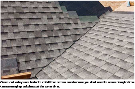
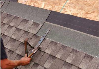
Подпись: Closed-cut valleys are faster to install than woven ones because you don't need to weave shingles from two converging roof planes at the same time. Подпись: Roofing Jacks Roofing jacks provide safe, affordable platforms, even on slopes. Typically, install a pair of jacks for every 8 to 10 courses you go up the roof. To attach the jacks, level the pair by aligning the jacks to horizontal chalklines, and drive two 10d galvanized common nails through each jack into rafters. (Jacks nailed only to sheathing are unsafe because they may pull out under load.) Place jack nails above the fastener line on the shingle because the nails will stay in place after jacks are removed. If you space each pair of jacks 8 ft. apart horizontally, they can be spanned by 10-ft.-long planks that allow a 1-ft. overhang on each end. However, install the two shingle courses above the jacks before you insert the plank; otherwise the plank will prevent your nailing those courses. To prevent a plank from sliding out of a jack, nail through the hole in the front of the jack arm, into the plank. Plank-and-jack removal is a two-person job, especially in windy weather. Above all, play it safe, first removing the plank to a secure location. To remove a jack, sharply hammer its bottom upward, thereby driving the slotted jack holes off the 10d nails. Then, while being careful not to disturb the overlapping shingles, slide the jack out. It's a good idea to drive jack nails flush, but not imperative. To drive them flush, slide a flat bar under the overlapping shingle, placing it atop the nail head; then strike the bar's handle with a hammer. This may require several blows. image169

There are many ways to lay out and install shingles. If you’re installing laminated shingles, a pyramid pattern is best. With this method, you precut a series of progressively shorter shingles, based on some multiple of the offset dimension. Because each successive course is, say, 5 in. or 6 in. shorter, the stepped pattern looks like a pyramid. Typically, pyramids start along a roof edge, with the first shingle in each course flush to the rake starter strip.

Once the pyramid is in place, the job goes fast. Just place a full shingle against each step in the pyramid and keep going. Because the offset is established by those first shingles, you can install full shingles till you reach the other end of the roof. But most roofers prefer to work up and out, maintaining the diagonal. If there are color varia­tions among bundles, they’ll be less noticeable if the shingles are dispersed diagonally.

The frequency of a pyramid pattern’s repeat­ing itself depends on how random you want shin­gles to look. Traditionally, patterns repeat every fourth course, that is, every forth course begins with a full shingle. Whatever pattern you choose, trimmed pyramid shingles should be at least 8 in. wide; otherwise they’ll look flimsy.

Keeping things lined up. As you work up the roof, align the top of each shingle to a horizontal exposure line. Chalklines wear off quickly, so don’t snap them too far in advance; snapping chalklines each time you roll out a new course of building paper is about right. However, to get the measuring done all at once, you can measure up from that original 12-in. line and use a crayon to mark off exposure intervals along the rake edges on both ends of the roof, and then snap chalk­lines through those marks later.

Alternatively, if you snap chalklines only every second, third, or fourth course, use the gauge on the underside of your pneumatic nailer or on your shingle hatchet to set exposures for interven­ing courses. If your shingling field is interrupted by dormers or such, always measure down to that original 12-in. line to reestablish exposure lines above the obstruction. Finally, if the ridge is out of parallel with the eaves by more than % in., stop shingling 3 ft. shy of the ridge and start adjusting exposures so that the final shingle course will be virtually parallel with the ridge.

For example, if there’s a discrepancy of 112 in., then at 3 ft. below the ridge, you’ll need to reduce exposures on the narrow end of the roof by % in. in each of six courses.

Valleys. Both open valleys (in which metal valley flashing is exposed) and closed valleys should be lined, as described in “Underlayment,” on p. 69. Closed valleys are more weathertight but slower

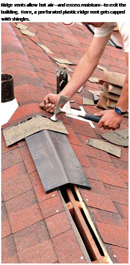
Подпись: PROnP As shingles run diagonally into an open valley, their leading edges often end in sharp points, under which water can run. To prevent that, use a utility knife with a hooked blade to clip points at a 45° angle. 1111 Подпись: Ridge vents allow hot air—and excess moisture—to exit the building. Here, a perforated plastic ridge vent gets capped with shingles. to install, so they’ve become less popular. Open valleys are faster to install and better suited to laminated shingles, which are too bulky and stiff to interweave in a closed valley.

Once you’ve installed valley flashing, snap chalklines along both sides to show where to trim overlying shingles. Locate chalklines at least 3 in. back from the center of the valley; oncoming shingles cover valley flashing at least 6 in. When nailing shingles, keep the nails back at least 6 in. from the valley centerline—in other words, 3 in. back from the shingle trim line—so nails can be covered by shingles above. To seal shingle ends to the metal flashing, run a bead of roofing cement under the leading edge of each shingle, and put dabs of cement between shingles. Ideally, you should not nail through the metal at all, but that could leave an inordinately wide area of shingles unnailed. Besides, self-adhering waterproofing membranes beneath the metal flashing will self­seal around the nail shanks.

As a shingle from each course crosses a chalk­line, use a utility knife to notch the shingle top and bottom. Then flip the shingle over and, using a straightedge, score the back of the shingle from notch to notch. Or, to speed installation, run shingles into the valley, and then, when the roof section is complete, snap a chalkline along their ends to indicate a cut line. To avoid cut­ting the metal flashing under­neath, put a piece of scrap metal beneath shingle ends as you cut, use a hooked blade in the utility knife, or use snips.

Finally, codes in wet or snowy regions may require that valleys grow wider at the bot­tom. In that case, move the bot­tom of each chalkline away from the valley center, at a rate of Z in. per ft.

RIDGE VENTS

To install a ridge vent, cut sheathing back at least 1 in. on either side of the ridgeboard. Run underlayment and shingles to the edge of the sheathing. Then nail the ridge vent over the opening, straddling the shingles on both sides. In most cases, the ridge vent is covered by cap shingles. Because shingles folded in this manner tend to split over time, it’s wise to double them.

Chapter 14 offers more information on venti­lation. But, in brief, you need a minimum of 1 sq. ft. of ventilation per 300 sq. ft. of roof sur­face. Install half the vent area as soffit vents on the underside of the eaves, and half as ridge vents. For example, if the roof surfaces total 2,500 sq. ft., vent surfaces should be 2,500^300, or 8.33 sq. ft. Ridge vents would therefore be half that, or 4.16 sq. ft. Your building supplier can explain the calculations, but 4.16 sq. ft. corre­sponds roughly to 33 lin. ft. of ridge vents, based on net free vent area (NFVA) charts.

CROSSCUTTING

A cut across the grain is called a crosscut. To make one, first scribe a cut line on the stock using a square to draw the line straight. Make sure that the stock is adequately supported either by sawhorses or by 2x blocks placed on the floor so that the cutoff can fall free. Then place the saw base on the stock with the blade about 1 in. from the edge of the wood and align the blade with the cut line. Hold the saw with both hands, pull the switch, and slowly push the blade into the wood, following the cut line. Going slowly and cutting straight helps prevent kickback (for more on preventing kickbacks, see the sidebar on p. 43).

To make a square cut without scribing a cut line in 2x4s and other narrow stock, align the front edge of the saw base parallel to the edge of the stock and make the cut. Try this a few times on scrap, check­ing each cut with a square to see how you’re doing.

CROSSCUTTING

A straightedge ensures a straight crosscut.

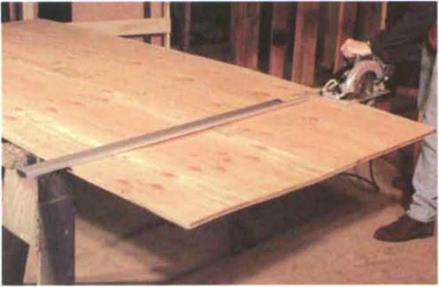
To make a long, straight crosscut, say on finish – grade plywood or across a door, clamp a good straightedge to the workpiece and slide the saw base along it as you cut (see the photo above). You can make your own straightedge, but I use a com­mercial one from Griset Industries (see Sources on p. 198) that is arrow-straight and easy to clamp to the workpiece.

Another way to make a straight crosscut is to use a shootboard, which is simply a straightedge with a fence (saw guide) screwed to it. You can buy a shootboard (Olive Knot Products makes an ad­justable one—see Sources on p. 198), but it’s pretty easy to make one.

Just cut two pieces of 1/2-in. plywood—one 8 in. wide and one 1V2 in. wide—as long as the material you wish to cut. Glue or screw the 11/г-іп. piece to one edge of the 8-in. piece. The wider piece will be the base, and the thinner piece will serve as the fence. Place the circular saw on the base against the fence and cut off any excess material.

To use a shootboard, clamp it to the workpiece with the front edge of the base right on the cut line.

Place the saw on the shootboard against the fence, reset the blade so that it extends 1/e in. below the stock, and cut. The base will also keep the wood fibers from tearing out at the end grain (for more on preventing tearout, see the sidebar on p. 47).

RIPPING

A cut along the length of a board is called a rip cut, and it can be done in several ways. Most ripping is done simply by cutting freehand along a pencil mark or chalkline that has been laid out on a board. Again, make sure the stock is adequately supported and that the saw isn’t forced or twisted during the cut.

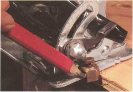
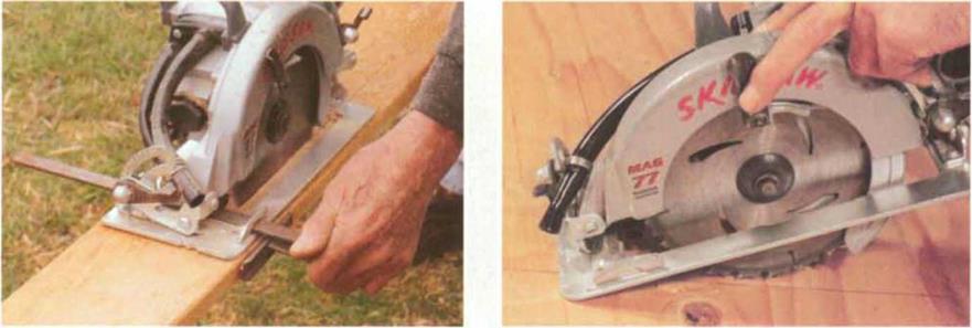
When you need an accurate rip cut, use a ripping – guide attachment. A good one is available from Prazi-USA (see Sources on p. 198). Another type of guide fits into the slots on the front of the saw base. Both guides work like a table-saw fence and can be adjusted to various widths (see the photo below). Both have a flange on one end that you hold against the edge of a board as you make the cut. If you have a flat saw base, you can attach a stair gauge to the front edge and use it as a ripping guide (see the photo at right).

PLUNGE CUTTING

A plunge cut is made in the middle of a board and is used, for instance, to cut a window opening in the center of a piece of plywood sheathing.

To make a plunge cut, lean the saw forward over the cut line so that it is resting on the front edge of the saw base with the blade about 1 in. from the wood (see the bottom right photo). Use the lever to raise
the guard and expose the blade, then start the saw and, using the front edge as the hinge point, slowly lower the blade into the wood. Hold the saw with both hands and continue the cut, following the cut line. When you get to the end of the cut, turn the saw off and let the blade stop spinning before pulling it out.

If you need to finish a cut near where you started, don’t try to back the saw into the cut. Instead, turn the saw around and finish from the opposite direction.

CROSSCUTTING

A stair gauge attached to a saw base makes a simple but effective ripping guide.

A ripping-guide attachment makes it easy to cut on a straight line, even on long stock. (Photo by Roe A. Osborn.)


To start a plunge cut, lean the front edge of the saw base over the cut line, and start the saw with the blade about 1 in. from the wood.


CROSSCUTTING

CROSSCUTTING

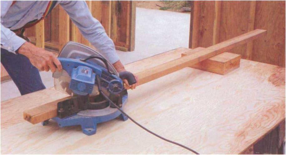
When cutting long stock with a miter saw (also called a chopsaw), support one end on an extension table, on a sawhorse, or on blocking, as shown here.


which can crosscut a 2×6, because of its versatility. Smaller models work well for cutting trim, while larger ones can cut through 4x stock.

There are now a variety of power miter saws that offer even greater capacity and versatility than the simple version just described. Some of the newest slid­ing compound miter saws have the capacity to crosscut up to a 4×12. They also tilt from side to side to allow you to make a compound (double-angle) miter cut. These saws are rugged enough for daily use by framers, yet are plenty accu­rate for finish work.

Some power miter saws come equipped with extension wings for the table, which can be useful for cutting relatively short stock. For longer stock, you may need extra support so that the stock
doesn’t lift and pinch the blade. Extension tables for miter saws are avail­able, but I usually support long stock with a block set to the side of a job – made table (see the photo above).

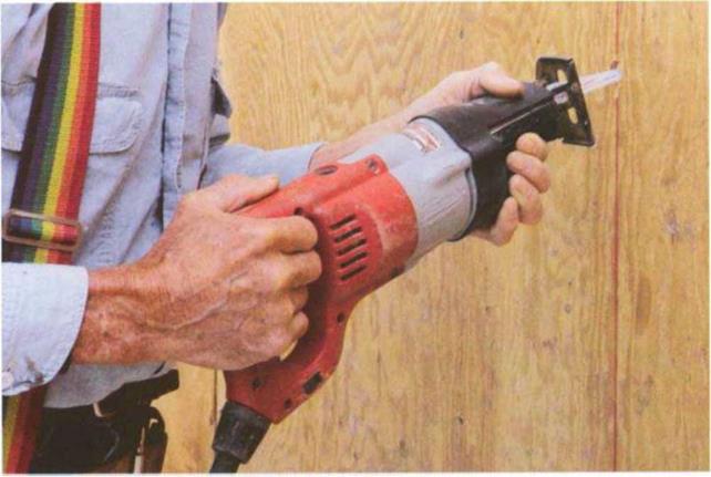
Reciprocating saw

Years ago, every carpenter had a key­hole saw for cutting in tight places. Nowadays carpenters use a reciprocating saw, which is basically a keyhole saw with a motor. It’s the tool of choice for remodeling work, such as tearing out walls, replacing doors and windows, or removing old cabinets, because it cuts through wood, metal (including nails and pipes), plaster, and plastic. It can also get into places you can’t reach with a circular saw: for instance, when you need to cut a hole in a subfloor right against a wall.

Preventing tearout
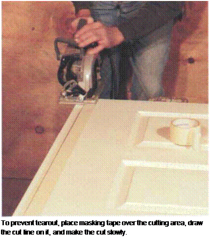
Подпись:

Tearout of wood fibers is a common occurrence when cutting wood, especially during crosscutting. This is okay for framing but not for finish work.

One way to prevent tearout is to lay a straightedge directly on the cut line and run a utility knife or a pocketknife along the line to score the wood fibers on the cutoff side of the line. This will prevent them from lifting up as the saw makes the cut.

Another way to prevent tearout is to lay a strip of masking tape over the area to be cut. The tape will hold the wood fibers in place during the cut. To prevent the tape from lifting any loose fibers from the wood when removing it, pull it toward the edge of the board.

The first reciprocating saws had only one speed, but most of them now have either a two-speed or a variable-speed switch. While wood can be cut at high speed, hard materials—such as metal pipe—need a lower speed to minimize the heat generated by friction. The variable-speed mechanism also makes it easier to do plunge cuts and precision work. When using a reciprocating saw (say, for cutting into an existing wall), be careful not to cut through plumbing or wires. It’s a good idea to shut off power to any nearby electrical circuits when making blind cuts, but it’s an even better idea to avoid making blind cuts when­ever you can. Use both hands when using this saw, and hold the shoe
against the material being cut to make the cut faster and safer (see the top photo on p. 49).

Reciprocating saw blades are available in lengths from Vh in. to 12 in. A good all-purpose size is 6 in., which is large enough for most jobs and easier to con­trol than longer blades. In general, use the shortest blade that will do the job. I prefer to use bimetal blades, which are more expensive than standard blades but can cut both wood and metal. If you bend a blade while cutting, don’t worry. Blades can usually be straightened and reused, and you usually don’t even have to take them out of the saw to do it.

Power-saw safety

• Stay alert at all times. Accidents happen not so much when we are still learning but when we think we have mastered a tool. As a beginner, your mind is focused and you are careful. But once you gain ex­perience, you may feel so confident that you pay less attention to what you are doing.

• Keep small children away from power saws (and other tools).

• Use sharp blades. Dull blades don’t cut well and can cause accidents.

• When changing blades, unplug the saw.

• If the saw has a blade guard, make sure it’s work­ing properly, and use it. Cut scrap wood to practice working with the guard in place so you can get used to it.

• Don’t force a saw. Let it work at its own pace. Forcing a saw can overload the motor, causing it to overheat.

• When you feel the blade bind in the kerf, stop and start over.

• Wear safety glasses or goggles.

• Wear a mask if you are sensitive to sawdust.

• Use hearing protection.

• Don’t use a power saw—or any power tool—when you are fatigued.

• Remove anything that might distract you, such as a loud radio.

• Keep your fingers away from the blade! Blow— don’t brush—sawdust away from the cut line to clear the line as you cut.

However, the blade can get quite hot when cutting, so be sure to use pliers, not your fingers, to straighten it.

figsaw

The first carpenter I learned from was a master with a coping saw, which he used to cut intricate patterns. I think he would have loved a power jigsaw (also called a sabersaw), which can literally cut circles around a coping saw. It’s a versatile tool used for cutting circles, curves, and irregular patterns, as well as for making sink cutouts in countertops.

Most jigsaws have an adjustable base plate that allows you to make angled cuts. And I recommend getting a jigsaw with a variable-speed control, which gives more control over the cut through various types of materials. Like its cousin the reciprocating saw, a jigsaw can cut through wood, ceramic tile, plastic, fiberglass, and metal—when equipped with the proper blade.

Jigsaw blades are designed to cut either on the upstroke or on the downstroke, depending on the blade. To avoid tearout on the finish side of a work – piece, keep the finish side down if your

CROSSCUTTING

When using a reciprocating saw, place one hand on the handle to control the switch and the other on the rubber boot at the front end of the tool.

CROSSCUTTING

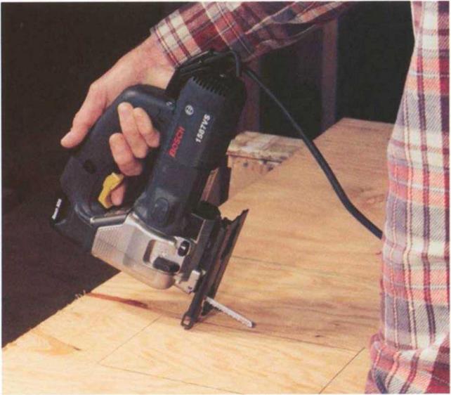
To start a plunge cut with a jigsaw, rest the front edge of the base plate on the workpiece with the blade clear of the wood. Start the saw and ease the blade into the wood.

blade cuts on the upstroke. Keep the finish side up if your blade cuts on the down stroke. To reduce vibration and chipping, hold the base plate firmly against the surface of the material when making your cut, letting the saw work at its own pace. If you push it too hard, especially through a knot, the blade could break. On a tight curve, cut very slowly so as not to bind or break the blade. And don’t brush sawdust away from the cut line with your hand; instead, blow the dust away and save your fingers.

Both jigsaws and reciprocating saws can cut an opening in thinner material, such as plywood paneling, without drilling an initial pilot hole. To make a plunge cut with a jigsaw, tilt the saw forward and rest the front edge of the base plate on the workpiece with the blade clear of the wood (see the bottom photo on
p. 49). Then start the saw and ease the blade slowly into the wood. Once the blade penetrates all the way through, the saw can be placed in its normal ver­tical position and the cut completed.