Posted by admin on 14/ 11/ 15
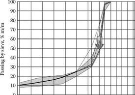
After examining the gradation curve in Figure 6.6, we can conclude that lowering the curve on the 8-mm sieve simply means a reduction in passing from 55 to 45%, which is an increase in the quantity of particles bigger than 8 mm from 45 to 55%. This move means that we should increase the content of 8/11.2 by 10%. This action should be balanced, so 10% has to be taken off the aggregate 5.6/8. As a result, the achieved composition of the mix is shown in Table 6.9 and the gradation curve in Figure 6.7.
TABLE 6.9
Example of the SMA Mix with an Uneven Distribution of the Coarse aggregate Fraction among Three Fractions— predominantly chippings 8/11.2 (example II, stage 4)
 component of aggregate mixture content, (m/m) component of aggregate mixture content, (m/m)
Filler 10%
Crushed sand 0/2 15%
Coarse aggregate 2/5.6 mm 5%
Coarse aggregate 5.6/8 mm 15%
Coarse aggregate 8/11.2 mm 55%
    0 0
10
 20 20
30
40
50
60
70
80
90
100
FIGuRE 6.7 Example of SMA mix with an uneven distribution of the coarse aggregate fraction among three fractions—the effect of the decrease in quantity of aggregate 2/5.6 and 5.6/8 combined with adding 10% aggregate 8/11.2 (Example II, Stage 4).
Posted by admin on 14/ 11/ 15
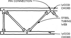 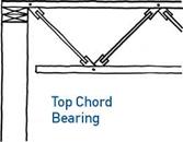 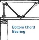
Wood top and bottom chords are linked with steel tubing webs in the composite truss. The tubing is pressed flat at the ends and connected to the wood chords with a metal pin. Unlike wood trusses with metal plates (see 45A above), the webs of the composite truss are entirely free to rotate (on the pins) and therefore allow the truss to return to its original shape when the load is removed.
Composite trusses are generally more heavy duty than their all-wood cousins illustrated in 45A above. The largest composite trusses are capable of spanning
over 100 ft. They are made with double 2x chords, which sandwich the webs. The lightest-duty composite trusses are made with single 2×4 chords oriented flat and dadoed to receive the webs.
Like wood floor trusses, composite trusses easily accommodate ducts and other utilities, which can be run through the open webs without altering the truss. Like all trusses, composite trusses are most practical for simple plans with long spans. Once engineered and installed, they are difficult to alter.
Posted by admin on 14/ 11/ 15
In his book, How Buildings Learn, Stuart Brand speaks of the difference between "use value” and "market value”:
Economists dating back to Aristotle make a distinction between "use value” and "market value.” If you maximize use value, your home will steadily become more idiosyncratic and highly adapted over the years. Maximizing market value means becoming episodically more standard, stylish, and in – spectable in order to meet the imagined desires of a potential buyer. Seeking to be anybody’s house it becomes nobody’s5
On the surface, small dwellings may seem to afford greater utility than marketability. These places are typically produced by people who are more concerned about how well a house performs as a home than how much it could sell for. The creation of a smart little house has traditionally been a labor of love because, until recently, love of home has been its only apparent reward. As a rule, Americans like to buy big things. Like fast food, the standard American house offers more frills for less money. This is achieved primarily by reducing quality for quantity’s sake.
Financiers have been banking on this knowledge for decades. From their perspective, a sound investment is one that corresponds with the dominant market trend. Oversized houses are more readily financed because they are what most Americans are looking for. For a lender, two bedrooms are better than one, because, whether the second room gets used or not, this is what the market calls for. Sometimes a bank will simply refuse to finance a small home because the cost per square foot is too high or the land upon which the house sits is too expensive in proportion to the structure. The design, construction or purchase of a small house has thus been further discouraged.
Despite all obstacles, a few relentless claustrophiles do continue to fight for their right to the tiny, and it has finally begun to pay off. Lawsuits concerning the constitutionality of minimum-size standards have recently forced some municipalities to drop the restrictions. Where this is the case, little dwellings have begun to pop up, and they are selling fast. Americans looking for smaller, well-built houses are out there, and their needs have been refused for decades. This minority, comprised mostly of singles, may be small, but it is ready to buy. It seems the composition of American households changed some time ago, and the dwellings that house them are just now being allowed to catch up.
Some developers on the West Coast have been quick to take advantage of the fresh market potential. In one high-income neighborhood, new houses of just 400 square feet are selling for over $120,000, and some at 800 square feet are going for more than $300,000. That is about 10 percent more per square foot than the cost of 2,000 square-foot houses in the immediate area. Needless to say, post-occupancy reports show that, though less expensive overall, these little homes have not had a negative impact on neighboring property values. In fact, the resale value of American houses of 2,500 square feet or more appreciated 57 percent between 1980 and 2000, while houses of 1,200 or less appreciated 78 percent (Elizabeth Rhodes, Seattle Times, 2001). Small houses appreciated $37 more per square foot.
Posted by admin on 14/ 11/ 15
ONE OF THE MOST important skills a carpenter learns over the years is training and trusting his or her eye.
And one of the best ways to develop this capability is to cut square by eye. Instead of using a square to mark a 90-degree cutoff line on a board, simply make a quick pencil mark for length on the board, line up a circular saw, and make the cut. Over the course of framing a floor or a wall, this method can save you plenty of time.
If you’re comfortable using a circular saw, it’s not difficult to master this technique. Position the saw with the blade aligned on the cutoff mark and the front of the saw’s base parallel with the edge of the board. As you make the cut, keep the base parallel with the board’s edge. Practice a few times on scrap, check each cut, and adjust the angle of the cut until you’ve got it right. Ir time, you’ll develop a "feel" for square.
  MAKE SQUARE CUTS BY EYE. To make a square cut, put the blade on the cut line and keep the front edge of the saw base parallel with the board. MAKE SQUARE CUTS BY EYE. To make a square cut, put the blade on the cut line and keep the front edge of the saw base parallel with the board.
 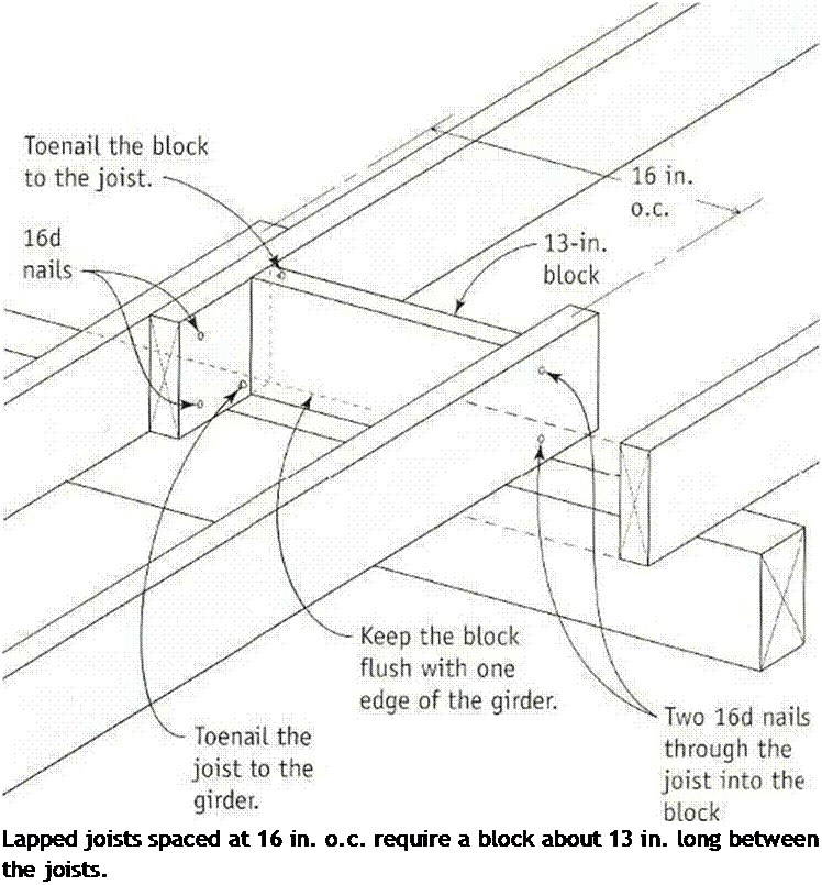
between the rim joists and the interior girders or crib walls in the basement or crawl space of an old house. Stress tests have long shown that bridging provides little extra stability to a floor sheathed with plywood or OSB. My experience is that most midspan bridging docs little except increase floor squeaks.
Blocking between joists, on the other hand, helps stabilize a building and keeps the joists from falling like dominoes under severe lateral stress, such as that generated by an earthquake or high winds. Blocking is installed at the bearing points where joists cross girders or crib walls. On many houses, this is also the spot where joists from opposite sides of the building lap against each other (see the illustration at right). To quickly cut dentical blocks with a circular saw, use a jig like the one shown in the sidebar on p. 70.
If you1 re building with I-joists, you’ll need to determine the length of the blocking on the
  і і
Helping Hand
Call for inspection. Don’t forget to call for an inspection of the joist system, the rough plumbing, and the ductwork once they are in place. Before the inspector arrives, remove all scraps of wood and other organic matter from the crawl space.
Posted by admin on 14/ 11/ 15
One of the first depictions of an Egyptian king is found on a macehead,[92] where the king is apparently opening a breach in a dike with a hoe, next to a man who is filling a basket with dirt. This king, called the Scorpion King from the ideogram on the mace – head, is said to have lived around 3200 BC. This is the period during which writing first appeared in Egypt, and also a time of growing political unity between upper and lower Egypt.
Development of the capital Memphis
Herodotus visited Egypt in 460 BC when it was under Persian domination. He reports (on the basis of information from priests) that a king called Min (Menes) built the new capital of unified Egypt, called Memphis, at the border between the upper and lower
portions. The construction of large dikes consummated the establishment of this city:
“The Egyptian priests say that Min, who was the first king of Egypt, dammed off this place of Memphis from the Nile. For the whole river flowed close by the sandy mountain that is toward Libya, but Min, damming up the southern bend of it, about a hundred furlongs south of Memphis, dried up the ancient channel and channeled the river to flow through the middle of the mountains. Even to this day this bend of the Nile is most heedfully observed by the Persians, that it may flow in its confined course, and every year the barriers are built up again. For if the river should break out at this point, there would be a danger that all Memphis would go down in the flood. When Min, this first king, had made the cut-off part into dry land, he founded within it the city that is now called Memphis – for Memphis, too, lies in this narrow part of Egypt – and, outside it, he dug a lake away from the river to the north and west (for the Nile itself was the barrier toward the east), and he founded within the city the temple of
o
Hephaestus, which is indeed a great one and exceedingly worth telling of.” °
Who is this Min? He is very likely the first identifiable Pharaoh, Menes or Narmer, who probably reigned between 3150 and 3125 BC[93] [94]. The dike he constructed at Memphis has been the subject of some speculation. Considering the difficulty of blocking a river like the Nile (and especially considering that this work would have been accomplished at the very beginning of the history of Egypt), it seems very unlikely that it was a true dam. Herodotus, who is considered to be a reliable witness, is careful to distinguish between what he sees and what he is told. He sees the dike, and he can see that it is maintained. It seems plausible that Memphis was founded by draining swampy land, perhaps in an abandoned branch of the Nile, and by then building the dike some twenty kilometers upstream to protect these drained lands from flooding. This dike had to be a dozen meters or so high, this being the height of the largest floods at Memphis.
The port of Memphis is without doubt the greatest in Egypt. It is thought to have been on the left bank, embedded in the valley of a wadi that flows along the edge of the plateau. The port is nearly a kilometer long and 200 to 300 m wide. It is connected to the Nile by a canal extending to the north along the edge of the plateau, providing access to the cultural and funereal sites of Saqqarah.[95] [96]
Posted by admin on 14/ 11/ 15
The lognormal distribution is a commonly used continuous distribution for positively valued random variables. Lognormal random variables are closely related to normal random variables, by which a random variable X has a lognormal distribution if its logarithmic transform Y = ln(X) has a normal distribution with mean xln x and variance оЩx. From the central limit theorem, if a natural process can be thought of as a multiplicative product of a large number of an independent component processes, none dominating the others, the lognormal
distribution is a reasonable approximation for these natural processes. The PDF of a lognormal random variable is

which can be derived from the normal PDF. Statistical properties of a lognormal random variable in the original scale can be computed from those of log – transformed variables as
Mx — A — exp ^ Mln x + j (2.66a)
el — МІ [exp (°-l2nx) – 1] (2.66b)
^2 — exp (ol2nx) – 1 (2.66c)
Kx — ^3 + 3^x (2.66d)
From Eq. (2.66d), one realizes that the shape of a lognormal PDF is always positively skewed (Fig. 2.19). Equations (2.66a) and (2.66b) can be derived easily by the moment-generating function (Tung and Yen, 2005, Sec. 4.2). Conversely, the statistical moments of ln(X) can be computed from those of X by
It is interesting to note from Eq. (2.67b) that the variance of a log-transformed variable is dimensionless.
In terms of the L-moments, the second-order L-moment for a two – and three – parameter lognormal distribution is (Stedinger et al., 1993)
(2.68)
in which erf( ) is an error function the definitional relationship of which, with
Ф(г) is
2 fx 2 fx
erf(x) — ^= e~“2 du — e-Z/2 dz — 2Ф(^/2x) – 1 (2.69)
Vn Jo vn Jo
Hence the L-coefficient of variation is r2 — 2Ф(о1пx Д/2) – 1. The relationship between the third- and fourth-order L-moment ratios can be approximated by the following polynomial function with accuracy within 5 x 10⁻⁴ for | r2 | < 0.9 (Hosking, 1991):
T4 — 0.12282 + 0.77518т32 + 0.12279т34 – 0.13638t36 + 0.11386r38 (2.70)
 
0.6
0.5
z
i – J
0.3 0.2 0.1 0
Since the sum of normal random variables is normally distributed, the product of lognormal random variables also is lognormally distributed (see Fig. 2.15). This useful reproductive property of lognormal random variables can be stated as if X1,X2,…,XK are independent lognormal random variables, then W = b0nK= 1 Xbb has a lognormal distribution with mean and variance as
K K
M-ln w = ln(b0) + 53 bk M-lnXk °ln w =53 bk alnxk
к = 1 k = 1
In the case that two lognormal random variables are correlated with a correlation coefficient pXyy in the original scale, then the covariance terms in the
log-transformed space must be included in calculating аЩ w. Given px, y, the correlation coefficient in the log-transformed space can be computed as
Corr(ln X, lnY) = Pln x, ln y = , ln(1 + Px’yUx Uy) (2.71)
^ln(1 + Д2) x ln(1 + Д2)
Derivation of Eq. (2.71) can be found in Tung and Yen (2005).
Example 2.18 Re-solve Example 2.17 by assuming that the annual maximum flood magnitude in the river follows a lognormal distribution.
Solution (a) Since Q has a lognormal distribution, ln( Q) is normally distributed with a mean and variance that can be computed from Eqs. (2.67a) and (2.67b), respectively, as
Qq = 4000/6000 = 0.667 afn Q = ln(1 + 0.66 72) = 0.3 68 MlnQ = ln(6000) – 0.368/2 = 8.515
The probability of the annual maximum flood magnitude exceeding 10,000 ft3/s is P (Q > 10, 000) = P [ln Q > ln(10, 000)]
= 1 – P [Z < (9.210 – 8.515)/V0.368]
= 1 – Ф(1.146) = 1 – 0.8741 = 0.1259
(b) A 100-year flood qw0 represents the event the magnitude of which corresponds to P(Q > <7100) = 0.01, which can be determined from
P(Q < 7100) = 1 – P(Q > 7100) = 0.99
because P(Q < 7100) = P [ln Q < ln(q100)]
= P {Z < [ln(7100) – Mln Q]/oln Q1
= P{Z < [ln(q100) – 8.515]/V0.368}
= Ф{[1п(7100) – 8.515]Д/0.368} = 0.99 From Table 2.2 or Eq. (2.64), one can find that Ф(2.33) = 0.99. Therefore,
[ln(q100) – 8.5151Л/0.368 = 2.33
which yields ln(q100) = 9.9284. The magnitude of the 100-year flood event then is q100 = exp(9.9284) = 20, 500 ft3/s.
Posted by admin on 14/ 11/ 15
Tile and slate are relatively brittle, expensive, and easily damaged if you don’t know what you’re doing. And they’re slippery when wet. In most cases, hire a pro to make repairs.
Tile and slate are so durable that they often outlast the underlayment and fasteners. So when repairing or replacing these roofs, prolong the life of the installation by using heavy under – layment (30-lb. building paper or a self-adhering bituminous membrane), copper attachers, and copper flashing. Although these materials are expensive, if the roof lasts upward of 60 years without leaking, it’s money well spent.
Roof tiles weigh about three times as much as asphalt shingles. So if you’re thinking of installing a new type of tile or tiling a roof for the first time, have a structural engineer evaluate your situation. Your roof framing may need bolstering to support the additional load.
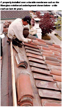   Tiles are available as two-piece, mission-barrel tiles; as one-piece, low-profile concrete tiles; and as flat-shake tiles, which mimic wood shakes. Tiles overlap to direct rain into tile channels. Traditionally, tiles were set without nails on wood battens or skip-sheathing. But today they are commonly nailed to plywood sheathing, especially if the roof pitch is 5-in-12 or steeper. Two-piece mission tiles are nailed in two manners: Trough tiles are nailed directly to sheathing. Cap tiles, which sit atop trough tiles, are attached to intervening copper wires nailed to the roof. Tiles are available as two-piece, mission-barrel tiles; as one-piece, low-profile concrete tiles; and as flat-shake tiles, which mimic wood shakes. Tiles overlap to direct rain into tile channels. Traditionally, tiles were set without nails on wood battens or skip-sheathing. But today they are commonly nailed to plywood sheathing, especially if the roof pitch is 5-in-12 or steeper. Two-piece mission tiles are nailed in two manners: Trough tiles are nailed directly to sheathing. Cap tiles, which sit atop trough tiles, are attached to intervening copper wires nailed to the roof.
Slate roofs are most often damaged by tree limbs. You can usually make repairs safely if the damage is along an edge and hence reachable without requiring that you walk on the roof. If you note a number of missing slates and concomitant rust stains on the roof, the nails may be rusting through, creating an extremely dangerous situation. Call a slate specialist at once.
To repair incidental damage, buy a slate hook. Work the head of the tool up under the damaged piece until the tool’s hooked head catches a nail shank. Then strike the handle of the tool with a hammer to cut through the nail shank. When both shanks are severed, slide out the damaged slate, being careful not to disturb adjacent pieces.
Once the damaged slate’s on the ground, transfer its dimensions onto a replacement slate. Then rent a tile-cutting saw to cut the new piece, wearing goggles. Or ask a tile dealer to cut the piece for you. Ideally, the new piece should be the same size as the one it’s replacing, but old nail shanks may prevent sliding a full-size replacement piece into place. In this case, trim the replacement piece further.
That done, align the bottom edge of the replacement slate to others in the course. Predrill two nail holes, each one 1 in. from the edge and about 1 in. below the course above; you’ll probably be drilling through two layers of slate, so take it slow. (A cordless drill is ideal for this task.) Size the drill bit just slightly larger than the thickness of the nail shank. Because this pair of nails won’t be covered by the slate above, caulk all holes with urethane before inserting nails. Drive the nails down just snug and no more, so you don’t split the slate.
METAL ROOFS
Although metal roofs tend to be quite durable, nail maintenance is key to their longevity. Most leaks occur when wind and ice lift the sheeting and pop nails up.
At least once a year and after major storms, study the roof with binoculars, and nail down any pop-ups. For extra security, put a dab of urethane caulk beneath nail heads. (Although roofing cement works too, it would be unsightly.) If popped nails seem loose, upsize the nail or use a screw.
To avoid galvanic-action corrosion, use nails or screws that are compatible with the roof metal. By the way, nail or screw metal roofing only at the raised crests, not in troughs where the water runs.
 If the roofing is rusted but serviceable, use a wire brush on the surface to remove the rust and paint on an elastomeric roof coating, such as Gacoflex® acrylic latex. An elastomeric coating is necessary because metal expands and contracts. Incidentally, such coatings can also extend the life of metal gutters. If the roofing is rusted but serviceable, use a wire brush on the surface to remove the rust and paint on an elastomeric roof coating, such as Gacoflex® acrylic latex. An elastomeric coating is necessary because metal expands and contracts. Incidentally, such coatings can also extend the life of metal gutters.
| |
 expelled. But large particles such as pollen, pet dander, and dust mites must be cleaned up or vacuumed rather than exhausted or diluted because they’re too heavy to mix with air. Other large particles, called semi-VOCs, are solids or liquids at room tempera – ■* ture. While they’re not gaseous, as with VOCs, they are volatile enough to emit lots of gaseous vapor. This is important, because if you filter out SVOC particulates you haven’t really done anything until you clean the filter; the SVOCs keep emitting gaseous vapor from the filter. If you don’t replace filters on your HVAC system regularly, the system itself becomes a contamination source.


 Fig. 3.8 Falling head permeability test
 component of aggregate mixture content, (m/m)
 0
0


 і
і


 Tiles are available as two-piece, mission-barrel tiles; as one-piece, low-profile concrete tiles; and as flat-shake tiles, which mimic wood shakes. Tiles overlap to direct rain into tile channels. Traditionally, tiles were set without nails on wood battens or skip-sheathing. But today they are commonly nailed to plywood sheathing, especially if the roof pitch is 5-in-12 or steeper. Two-piece mission tiles are nailed in two manners: Trough tiles are nailed directly to sheathing. Cap tiles, which sit atop trough tiles, are attached to intervening copper wires nailed to the roof.
 If the roofing is rusted but serviceable, use a wire brush on the surface to remove the rust and paint on an elastomeric roof coating, such as Gacoflex® acrylic latex. An elastomeric coating is necessary because metal expands and contracts. Incidentally, such coatings can also extend the life of metal gutters.