Tracer Test

Tracer tests involve the injection of an inert solution, or tracer, into an existing flow field via a borehole or a well. Tracer tests are often desirable because they are passive-type tests and do not place unnatural stress conditions on the flow system.

The dilution rate of the tracer at the injection well or its time of travel to another well can be used to calculate the water velocity and ultimately the permeability. Detection of the tracer, or concentration measurements, can be made by either manual or probe sampling. Commonly used tracers are radioisotopes, salt solutions and fluorescent dyes.

WALLS AND PARTITIONS

The key to economical wall and parti­tion construction is preplanning to eliminate unnecessary materials and labor. Carpenters usually find extra material is needed here and there to accommodate doors and windows.

They may also follow traditional training by adding studs where partitions intersect exterior walls, blocking at mid-height of walls, double studs and headers at openings in nonbearing walls, and similar practices. Each of these excessive material uses is avoidable through proper attention in the planning stage. They add significantly’to cost without benefit to the home buyer.

Cost savings will be greatest when the overall out-to-out dimensions of the house and the location of wall openings coincide with a module of 2 feet. This provides maximum use of materials that are available in 2-foot increments and reduces scrap and waste.

An important side benefit to preplan­ning will be education of the car­pentry crew. When the crew has built a number of units in accordance with cost saving techniques presented in this section, less detailed instructions and fewer on-site modifications will be required.

Tilt-up wall construction continues to be the preferred method for reducing labor and material costs. Assembling wall sections to the greatest extent possible prior to erection is beneficial since materials do not have to be held up while they are being fastened. This includes framing and sheathing (if used), as well as siding, windows and exterior trim. Fabrication can be done on a shop table or right on the floor deck. Use end nailing, not toe- nailing, to fasten plates to studs.

Подпись: OVE TechniquesWALLS AND PARTITIONSEngineering analysis and testing have resulted in widespread acceptance of many changes in traditional wall framing techniques. Many of these OVE (Optimum Value Engineered) techniques were developed and tested by NAHB National Research Center.

Building 7’6"high walls instead of 8’0" saves approximately one course of siding or two courses of brick, 6 percent of wall insulation, 3 percent of painting labor and material, one tread and riser on a flight of stairs, and 9 to 12 inches of stair landing space.

A lower ceiling height also increases the structural capacity of studs acting as a column. The savings in material and labor more than offset the extra labor to cut 6 inches from the top of the gypsum wallboard panels.

Placing studs 24 inches on center, instead of 16 inches, reduces framing labor and material. The 24-inch on – center spacing is permitted in most areas of the country for one story and the second story of two story construction. Use of 24 inch spacing saves nearly a third of the regular studding.

Single top plates can be used when studs and trusses are in line on 24- inch centers so that the weight of the truss bears directly on the stud. Special connectors to splice joints in the top plate or to tie corners are not required because the floor or roof system attached to the top plate serves this function. This technique eliminates one-third of the plate material.

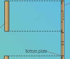
When studs sit directly over floor joists, the bottom plate is used only to facilitate alignment of the studs, and to provide a nailing base for wallboard, sheathing and baseboard, and not to carry weight from the stud

WALLS AND PARTITIONS

to the joist. Since the bottom plate doesn’t have to be as strong, a 1×4 is sufficient.

Because the maximum load on the corner studs in an exterior wall is one-half or less than the load on a regular stud, two-stud comers are more than adequate structurally. The third stud in the normal three-stud corner post serves only to back up the interior finish, and can be eliminated. Metal drywall clips or wood blocks can be used to backup the wallboard.

Similarly, partition posts built into the exterior wall for attachment of. interior partitions can be eliminated. The partition can be nailed to a mid­height wall block, and wood blocks or drywall clips can be used to backup the wallboard.

WALLS AND PARTITIONS

Ceiling nailers can be replaced with drywall clips. Since they secure the ceiling gypsum board to the walls, the clips offer the additional advan­tage of keeping the ceiling and wall gypsum board from separating. Mid­height "firestop" wall blocking can be eliminated. Wall plates, floor sheath­ing, and insulation provide sufficient constriction of air flow within the wall to minimize fire spread, and the blocking is not required for structural bracing.

Headers or lintels, and jack (jamb) studs which support them are required only where loads must be carried to the sides of window and door open­ings. If the loads don’t exist, or if other members, such as roof trusses, joists, joist bands, large areas of structural sheathing, or second story headers carry all or part of the loads across the openings, headers can be eliminated or downsized.

Openings in nonbearing walls can have single 2×4’s on each side to which windows and doors are fastened.

Headers and jack studs can also be eliminated in load-bearing walls when windows 22 1/2 inches or less in width are used and placed between the studs.

Other types of headers may be more economical than the single or double 2×8 header. Glue-nailed plywood box headers normally cost less and also provide extra space for insulation.

These headers are formed by glue- nailing a plywood skin to one or both sides of framing members above openings in a load-bearing wall.

Water resistant structural adhesives of the casein, urea formaldehyde, urethane or phenolresorcinol type should be used to glue the plywood, and nails spaced 6 inches or less along all frame members. .

The face grain of the plywood must be oriented horizontally over the opening, and the top plate must be continuous across the opening. Jack studs are not necessary on openings 4-feet wide or less. Use American Plywood Association exterior grade AC plywood.

If used on the inside surface, butt gypsum board to the plywood, tape and spackle the joint, and apply a thin coat of spackling compound to any plywood rough spots or patches. When* painted, there is no apparent dif­ference between the plywood and gypsum board surfaces.

Manufactured plywood joists and trussed joists can also make cost- effective headers while providing room for extra insulation. Check with the manufacturer for engineered sizes and prices.

Brick veneer costs can be reduced by: starting the brick at floor joist level on 8-inch blocks resting on 16-inch footings, instead of below grade on 12-inch blocks resting on 20-inch footings; using other materials above and below windows and in areas less subject to deterioration, e. g., the gables and the top half of a wall; building the walls 7’6" high instead of 8 feet.

Single-layer panel sidings (plywood and hardboard) are available for application directly to studs, eliminating the need for a separate sheathing.

Returning gypsum wallboard to the

windows and using drywall corners instead of using wood stool and casings saves money. Similarly, using drywall returns on bi-fold or bypass closet doors eliminates wood jambs and casings.

Providing a full width opening at the front, dimensioned to receive a standard width bi-fold or sliding door, eliminates jacks and studs beside the opening, and floor-to-ceiling doors eliminate framing and drywall over the opening. Drywall contractors often charge for a full wall even if only partially covered.

Interior nonbearing partitions can be built from 2×3 studs. Also, if floor sheathing is 5/8 inch or thicker, no blocks or joists need to be framed below nonbearing partitions. Where partitions are parallel with ceiling joists or roof framing overhead, use precut 2×4 blocks spaced 24 inches on center to secure the top of the parti­tion and to provide drywall backup.

Cabinet bulkheads can be eliminated. Install ceiling high cabinets, or let the top of standard height cabinets be an extra "shelf.

Light gage steel studs have been available for a number of years and are used extensively in commercial and high-rise apartment construction. They are usually installed by the drywall contractor. Steel studs are often cost effective, especially when lumber prices are high, but have not been widely used in single-family or low-rise multi-family construction.

WOOD FRAME FLOORS

Most wood frame floors utilize nominal 2-inch thick joists placed on a center­bearing beam and covered with sheath­ing. Floor trusses have recently become more popular and post-and – beam crawl space floors have been in use in some areas for years.

Floor design is based on a number of factors, such as:

• Design load

• Lumber species, size, and grade

• Clear span between supports

• Floor sheathing materials and thickness

• Fastening techniques

Utilization of full span capacity of lumber joists can often save between 6 and 8 percent of joist framing costs.

If allowable spans for joists presently used exceed the spans shown on the floor plan by 1 foot or more, impor­tant savings may be realized by changing either the joist grade, spacing, or size.

Built-up wood girders are usually more cost effective and easier to work with than steel girders.

Floor sheathing adds stiffness to the floor and, depending on thickness and fastening methods, can result in reducing the size and/or increasing the spacing of framing members.

When a plywood subfloor is properly glued and nailed to the joists, the subfloor and joist act together as a composite T-beam and as such will span a greater distance than if the subfloor is fastened with nails only. Glue-nailing is also effective in reducing floor squeaks and stiffens the floor. A single layer tongue-and- groove system is usually less costly than a separate subfloor and under- layment system.

Bridging or blocking between floor joists at mid-span has been proven ineffectual in almost all cases. An extensive series of tests conducted by the NAHB National Research Center in the early 1960’s proved that mid-span bridging adds nothing but cost to most floor systems. Major model codes

WOOD FRAME FLOORS

require bridging only in floors with joists exceeding a depth-to-thickness ratio of 6 to 1 based on nominal dimensions. In other words, joists up to and including 2x12s do not require mid-span bridging.

Another common but unnecessary practice is to double floor joists under nonbearing interior partitions. In fact, it is not necessary to locate nonbearing partitions over any joist when 5/8-inch or 3/4-inch plywood subfloor is used. The weight of the partition does not warrant extra support. Load-bearing interior walls usually run perpendicular to joists and do not require added support. If load­bearing walls run parallel to floor joists, a supporting girder sj’stem is required.

Wood frame floors must be anchored to the foundation to resist wind forces acting on the structure. In conven­tional construction practice, 2×6 sill plates are attached to the foundation with anchor bolts, and floor joists are toe-nailed to the sill plate.

Metal anchor straps are available for embedding in the foundation concrete or mortar that do not require holes in the sill plate. Such straps are less exacting and do not interfere with joist or band joist framing as anchor bolts often do.

Sill plates can be eliminated altogether if the top of the foundation is suffi­ciently level and accurate. Joists, however, must rest on a solid surface and not over the cores of concrete block. Anchorage can be provided by anchor straps attached to the joists and firmly set in foundation concrete or mortar.

Floors built on pressure treated wood foundations do not require separate sill plates or anchoring devices.

Joists are toe-nailed directly into the foundation wall top plate.

Stairwell framing costs can be reduced in the design stage by positioning stairwell openings parallel to floor joists. Double joists (trimmers) on each side of the opening are not necessary where the header which they support is located within 4 feet of the end of the joist spans. A single header is generally adequate for openings up to and including 4 feet in width.

The band joist (sometimes called the rim or header joist) typically is the same size as floor joists. The major function of the band joist is to keep the floor joists vertical. Therefore, if wall studs and floor joists are aligned, a nominal 1-inch thick board or plywood band is adequate.

In certain cases, the band may be eliminated altogether. When a structural exterior wall sheathing is used, it can extend over the ends of the floor joists where the band would
normally be. Joists must be temporar­ily braced until the wall sheathing is applied.

The typical wood frame floor has two joists lapping over the center girder, each joist acting independently from the other. This system creates pro­blems with plywood sheathing layout, one side of the floor being 11/2 inches out-of-kilter with the other.

The allowable span of floor joists may be increased by maintaining continuity over the center bearing – that is, if the joist is continuous rather than lapped over the girder.

If two joists of unequal length are spliced together so that the splice occurs at a point off center, an increase in stiffness of up to 40 percent is possible. This off-center- spliced-joist technique can result in reduced lumber size, increased spacing, or both. In addition, subfloor layout is greatly simplified.

WOOD FRAME FLOORS

EXAMPLES FROM THE DEMONSTRATION PROJECTS

However, the added cost of end trimming and splicing the joists must be considered. A Research report titled Off-Center-Spliced Floor Joists (143-51 is available from NAHB. 15th & M Streets NW, Washington, DC 20005.

Floor trusses are becoming more popular as alternatives to conventional wood frame floors. They are usually more costly but have the advantage of greater spans between supports, thereby creating greater floor plan flexibility. There are several different floor truss designs, some with open webs and some with a continuous plywood web. Open web trusses have the added feature of providing plumb­ing, wiring, and sometimes HVAC chases without drilling or cutting.

The major disadvantage of single-span floor trusses is the height of the trusses. In order to span greater distances, the truss must be much deeper than conventional 2x framing. This adds extra costs to sheathing, siding, stairs, etc. These, plus the extra cost of the floor itself, should be analyzed versus the value of the clear span.

JVAH Floors

Innovative floor framing methods were used on several JVAH sites. Some were unique while others were known methods not normally used in the local area.

Tulsa, Oklahoma

As discussed in the Foundation section, Wayne Hood built the Plenwood system in his demonstration homes. The wood frame floor portion of the system consisted of 2×8 floor joists spaced 24 inches on center with glue-nailed 3/4-inch plywood.

John Phillips constructed one of the most innovative wood frame floors in the demonstration. Typically, in the Lacey area, the foundation/ floor system consists of a conventional spread footing, a cast-in-place concrete foundation wall, a post-and – beam center bearing girder, 2×10 joists spaced 16 inches on center, and a two layer sheathing/underlayment system.

Подпись: Lacey, Washington Phillips designed and built a system that used 2x6s, spaced 24 inches on center, spanning about 8 feet between post-and-beam supports. Band joists were eliminated. Floor framing did not come into contact with the perimeter foundation at all. The first interior support girder was placed about 4 feet from the foundation wall and the joists cantilevered about 2 feet toward the foundation.

WOOD FRAME FLOORS

WOOD FRAME FLOORS

The 2-foot gaps at the ends of the floor joists and the 2-foot spacing where the joists are parallel to the foundation were easily spanned with 3/4-inch tongue-and-groove glue-nailed waferboard. Floor construction costs were reduced by an average of $852 when compared to the conventional floor.

Christian County, Pup Robertson also built an innovative
Kentucky floor system that saved $295 per

house. Instead of the conventional 2×8,16-inch on-center joists over a single center girder, he used two box girders spaced about 8 feet on center and 2×6 joists at 24 inches on center. He used 3/4-inch glue-nailed T&G plywood instead of the more conven­tional 1/2-inch underlayment.

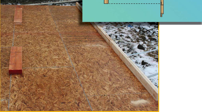
Подпись: Fairbanks, AlaskaTom Webb designed and built a cantilevered front porch deck by continuing the interior stair landing joists through the front door opening. This eliminated deep porch footings and foundations which are very susceptible to frost heave in Fairbanks.
WOOD FRAME FLOORS

Concrete

Introduction

Concrete is widely used in residential con­struction for footings, stem walls, and exposed basement flooring, as a subfloor for slab-on – grade construction, and as a finished floor material. Concrete consists of cement (usually Portland cement), water, and sand and other aggregates.

Once cured, concrete becomes an inert product and is not usually associated with toxic exposure, although there may be some more subtle health effects. (Refer to the essay by George Swanson to learn more about these effects and about products that can be sub­stituted for Portland cement.) Certain com­mon construction practices can make con­crete harmful to human health and should be avoided. These practices are discussed in the following sections.

Components of Concrete

Cement

Cement is the “glue” that holds the various components of concrete together and com­prises approximately 18 percent of the con­crete by volume. Concrete is high in embodied energy because of the tremendous heat re­quired to make cement. Cements are often advertised as “green” because they substitute a waste product for Portland cement. The re­placement of Portland cement with fly ash has become a common practice. However, fly ash can be a byproduct of the incineration of toxic or hazardous waste. We therefore believe that cement products containing fly ash should be used only if it can be determined that it is de­rived from a nonhazardous source.

Although it is difficult to build a home to­day without the use of some concrete, there are many strategies, discussed throughout the book, that we can employ to reduce our use of Portland cement.

Water

Clean, potable water should be specified for mixing concrete:

• Water shall be of potable quality, free of taste, color, and odor, and should not foam or fizzle.

Aggregate

The aggregate component accounts for 60 to 80 percent of concrete volume. The size and characteristics of the aggregate will affect the quantities of cement and water required and
the compressive strength, weight, and sur­face character of the finished concrete. Aggre­gate materials range in size from fine sand to crushed rock pieces. Sometimes recycled ma­terials are used as aggregate and these may be a source of contamination. Recycled industrial waste products may contain hydrocarbons and sulfur. If the source is an industrial pro­cess with residual heavy metals or toxic com­pounds, it can result in a product with toxic properties.

Installation, in a Nutshell

Today, most doors, windows, and skylights are preassembled in factories and delivered preframed, which makes installation much easier. Basically, you screw or nail the unit’s squared frame to a rough opening (RO). If the opening is in an exterior wall, weatherproof it first-wrap, flash, and caulk. Rough openings are typically Уг in. to 1 in. wider and taller than the outside dimension of the door or window frame being installed.

However, rough openings are rarely square or perfectly sized, so you need to insert shims (thin, tapered pieces of wood) between the square frame and the out-of-square open­ing. Shimming takes patience. But if you install shims well, doors, windows, and skylights will operate freely, without bind­ing. Once a preframed window or door is installed in its RO, insulate or spray foam between the frame and the RO to further block moisture and drafts. Then cover those gaps with casing (or trim) inside and out.

In general, avoid precased units, which have casing pre­attached to frames. It’s difficult to shim between the frame and the rough opening if casing’s in the way.

As you level and plumb windows and doors, use pairs of taperec shims to hold units in the rough openings. Use trim-head screw when tacking frames. They are easier to remove when adjusting shims and less likely to bend than finish nails. And their small heads are easy to sink, fill, or cover with a stop.

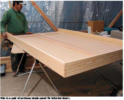
Подпись: This is a pair of prehung single-panel fir interior doors.

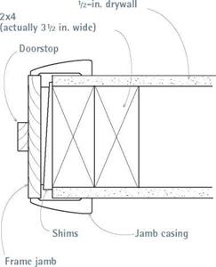
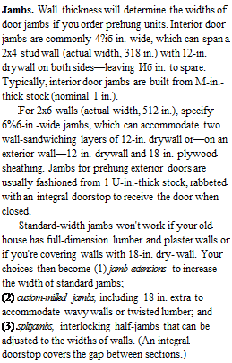
Подпись: Jambs. Wall thickness will determine the widths of door jambs if you order prehung units. Interior door jambs are commonly 4?іб in. wide, which can span a 2x4 stud wall (actual width, 318 in.) with 12-in. drywall on both sides—leaving Иб in. to spare. Typically, interior door jambs are built from M-in.-thick stock (nominal 1 in.). For 2x6 walls (actual width, 512 in.), specify 6%6-in.-wide jambs, which can accommodate two wall-sandwiching layers of 12-in. drywall or—on an exterior wall—12-in. drywall and 18-in. plywood sheathing. Jambs for prehung exterior doors are usually fashioned from 1 U-in.-thick stock, rabbeted with an integral doorstop to receive the door when closed. Standard-width jambs won't work if your old house has full-dimension lumber and plaster walls or if you're covering walls with 18-in. dry- wall. Your choices then become (1) jamb extensions to increase the width of standard jambs; (2) custom-milled jambs, including 18 in. extra to accommodate wavy walls or twisted lumber; and (3) splitjambs, interlocking half-jambs that can be adjusted to the widths of walls. (An integral doorstop covers the gap between sections.)
image189
Подпись: A standard frame jamb, which is 49/ie in. wide, can span a stud wall sandwiched between '/2 in. drywall panels

Height. Standard door height is 6 ft. 8 in., for both interior and exterior doors on newer houses. Older houses (1940s and earlier) sometimes had doors 7 ft. high, so that size is still widely avail­able. Of late, 8-ft.-high French doors are in vogue. Of course, you can special-order a door of virtually any size if you’re willing to pay enough. Salvage yards are excellent sources of odd-size doors.

Swing. Door swing indicates which side you want the hinges on. Imagine facing the door as it swings open toward you: If the door knob will hit your right hand first, it’s a right­handed door; if your left hand grabs the knob, then it’s a left­handed door.

Type and style. Hinged single doors are by far the most com­mon type, but they need room to operate. If space is tight, con­sider sliding doors, pocket doors, or bifolds. For wide openings, note that hinged double-doors individually weigh less and take less room to swing open than one massive door.

Try to match existing doors or those on houses of similar architectural periods. In general, frame-and – panel doors tend to go well with older houses; whereas flush doors have a more contemporary look. For that reason, sliding doors on older homes are usually placed on the back side of the house so they don’t look inconsistent with the front and side facades.

Interior Wall Cross Section

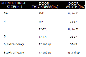
Подпись: TIPПодпись:Подпись: OPENED HINGE SIZE(in.) DOOR THICKNESS(in.) DOOR WIDTH (in.) 3'4 И-И Up to 32 4 И-И 32-37 T/S-T/S Up to 32 5 T/8-T/8 32-37 5,extra-heavy T/8 and up 37-43 6,extra-heavy T/8 and up 43 and up Construction and materials. For exterior doors, wood is the traditional favorite, but it requires a lot of maintenance. Consequently, wood doors come clad in vinyl or aluminum, and good-quality, insulated steel doors are virtually indistinguishable from wood once they’re paint­ed. Fire codes require steel doors between living spaces and attached garages or workshops. Exte­rior doors should have integral weatherstripping.
Given the rise of engineered lumber, it’s not surprising that many doors—both interior and exterior—are now made from plywood, hard – board, and so on. They can be stamped to mimic traditional panel doors and insulated to deaden sound and retain heat. They paint up nicely, can be cost-effective, and are generally more stable than solid wood.

Weatherstripping and glazing. Weatherstripping on exterior doors is often rabbeted into jambs, so it’s tighter and more energy efficient than any­thing you could install later. There is also a variety of thresholds and door bottoms available to keep snow or rain out, or to clear water so it doesn’t soak and destroy the bottom of the door.

If your exterior door has glass panels, they should be double glazed at the least; triple glazing is more energy efficient but costs more. Double glazing and a storm door may be a better choice. Finally, prefinish exterior doors with a UV – and water-resistant finish; at the very least, prime or seal all six sides.

Hardware. Hardware for prehung doors is pre­installed at the factory; then locksets and door handles are removed to prevent damage during shipping.

As indicated in "Sizing Hinges,” below, hollow – core or solid-wood interior doors up to 158 in. thick can be supported by two 352-in. by 352-in. (opened size) hinges; whereas 1 52-in.-thick exterior doors

Sizing Hinges

usually require three 4-in. by 4-in. hinges. Extra­heavy exterior doors may need even bigger hinges or hinges with ball bearings or grease fittings.

As shown in "Mortise Lockset,” on p. 103, and "Cylinder Lockset,” on p. 105, exterior locksets are most often cylinder locks, which require a 258-in. hole drilled into the face of the door, or mortise locks, which are housed in a rectangular mortise cut into the latch edge of the door. Mortise locks are more expensive and difficult to install, so they are most often used only on entry doors, with a thumb-lever handle. For added security, supplement exterior door locksets with a dead bolt and a reinforced strike plate.

Double exterior doors may have interconnected locksets, and flush bolts or surface bolts. Interior locksets are almost always some kind of cylinder lock: passage locks or latch sets on doors that don’t need to be locked and privacy locks or locksets on doors that do need locking, such as bedroom doors. Bathroom locks are specialized locksets with a chrome bathroom-facing knob to match plumbing fixtures.

Plan Components

Typical highway construction plans are made up of several individual components. The paragraphs that follow will present a brief discussion of various types of plan sheets that make up a set. Except for major projects, seldom will all of the compo­nents be required in a plan. However, when required, they are usually placed in the order discussed.

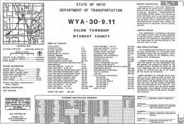
The title sheet is the first in the set and contains a brief description of the project and indication of its length. It displays the title of the project in large, bold letters. It lists the specifications under which the project is to be built, states whether traffic is to be maintained or detoured, gives an index of all plan sheets, lists standard construction drawings and supplemental specifications, and contains the signatures of approval by the appropriate officials. See Fig. 2.74 for an example.

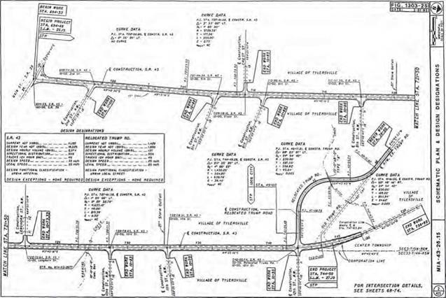
The schematic plan shows the geometric location of proposed roadway segments in relation to existing roadway segments and other major topographic features (rivers, streams, railroads, high-voltage lines, pipelines, etc.). See Fig. 2.75 for an example.

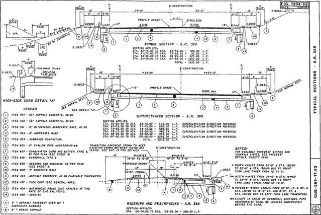
The typical sections sheet is a dimensioned cross-sectional view of how the road­way will appear after construction is completed. These sheets generally show lane widths, shoulder widths, pavement buildup, ditch design, foreslope and backslope rec­ommendations, and tie-ins to existing ground lines. Each section is accompanied by a set or sets of station limits identifying to which portion of the roadway it applies. See Fig. 2.76 for an example.

The general notes sheets contain plan notes to clarify construction items that are not satisfactorily covered by the specifications or plan details. They may be used to modify standard construction drawings.

The maintenance of traffic sheets may include plan view sheets showing location of temporary roads, temporary pavement widening, or detour routes, as well as sheets providing specific notes and instructions regarding sequential construction phases. Details included may be transverse sections showing relationships between the main­tenance roadway and the construction area, as well as placement of channelizing devices and lateral construction limits.

Подпись: ■ mnj bvWTjH ішшти» шигэт rr-Tz гтгтпгтгатт-г- WYA-30-8.11 NONE 3436 STP-49M81
Подпись: 214

Plan Components

Подпись: 215Plan Components

Подпись: 216Plan Components

The general summary sheets contain the itemized list of quantities on which the contractor bid and eventual payment will be based. Any items not listed on these sheets will contain a sheet number reference where they are listed elsewhere in the plans. Each item will usually have a sheet number reference indicating where the item may be found in the plan, or where a subsummary of this information may be found. See Fig. 2.77 for an example.

The calculations sheet provides a record of how quantity pay items were calculated. The sheet provides a way of checking these quantities and also usually indicates by station references where these items are used in the plans.

A storm water pollution prevention plan may be required by some agencies, depending on how much surface area is disturbed by construction. The threshold limit in Ohio is currently 5 acres (20 km2). The purpose of these sheets is to provide infor­mation on how storm water runoff is to be controlled during construction. Details shown will include the location of existing streams, lakes, wetlands, springs, etc., within 250 ft (76 m) of the construction area.

The plan and profile sheets show what an area looks like before and after construction of the project. In addition, they show quantities, dimensions, and other items required to lay out and construct the project. The sheet is normally divided into three areas— plan view, profile, and quantities. See Fig. 2.78 for an example.

The cross sections sheets contain a series of section “slices” of the roadway taken at regular intervals and are used primarily to determine the amount of earthwork and seeding required on the project. They may also be used to locate ditches, show proposed drainage features, design driveways, and establish limits of proposed right-of-way. See Fig. 2.79 for an example.

The miscellaneous details sheets are a section of the plans that serve as a “catch-all” for items that do not fit under other headings. Items that may appear on these sheets include approach slab details with elevations, driveway details, grading plans at inter­sections or interchanges, guiderail details, impact attenuator details, intersection details with elevations, linear grading details, pavement details showing elevations, superelevation tables, and noise barriers.

The drainage details sheets provide details for prefabricated structures and other drainage items that cannot be adequately shown on other sheets. These sheets include culvert details—not only the structure details, but also the grading plan in the vicinity.

Other specialized sheets that may be part of the plan are as follows:

Prefabricated structures Sanitary sewers Water lines

Traffic control (includes proposed signing, striping, and traffic signals)

Lighting

Landscaping

Cast-in-place structures (includes bridges, retaining walls)

Fence plan (refers to right-of-way fencing on limited-access projects)

Right-of-way (listing all affected property owners, parcel numbers, and required right-of-way to be purchased)

Soil profile and foundation investigation

Подпись: 218

FRAMING

There are many ways to frame walls, but it is always good to follow an organized sequence. This 16-step sequence has been developed over years of framing. Following these steps will help you and your crew work efficiently and eliminate errors. It will also ensure consistency from framer to framer. For example, if you have to leave a wall in the middle of framing it to go to another task, another framer can easily pick up where you left off and proceed without having to check every nail to see what you have done.

Keep in mind, walls must be square, plumb, and level. Measure accurately, cut straight, and nail tight.

Rake walls (sometimes referred to as gable end walls) typically start at the height of the standard wall and go up to the ridge of the roof. The challenge of building a rake wall is figuring the heights of the studs and making sure the wall is built square. Lifting the assembled rake wall into place can also be a challenge. This chapter will cover four ways to figure stud heights and build rake walls efficiently— using methods that will make your work easier.

FRAMINGStep 1-Spread Headers

^eadeisosc

\qv g° ^

S-Wr»,

Подпись: Heade:Подпись: Top plateFRAMINGачіш

Подпись: Header
Подпись: . sПодпись:FRAMINGThe steps outlined in the next pages follow the process of framing and sheathing the exterior walls in a horizontal position. The fully framed and sheathed wall is then lifted into position by using special lifting jacks or muscle power.
Spread headers in location close to where they will be framed.

Meeting Code

I should be clear that, despite the absurdities in their codebooks, our local housing officials are not necessarily absurd people. This is important to re­member if you are about to seek their approval for a project. Building codes are made at the national level, but they are adopted, tailored and enforced at the local level. View your housing department as the helpful resource it wants to be, not as an adversary. Once your local officials are politely informed about the actual consequences of the codes they have been touting, the codes are likely to change. Be sure to provide plenty of evidence about the merits of smaller houses, including documentation of projects similar to the one you intend to build. Codes are generally amended annually by means of a review and hearing process anyone in the community can take part in.

Diplomacy is one way of clearing the way for a small house. Moving is an­other. Some remote areas of the country have no building codes at all, and a few others have a special "owner-builder” zoning category that exempts people who want to build their own homes from all but minimal government oversight. Provisions for alternative construction projects also exist. Section 104.11 of the International Building Code encourages local departments to – weigh the benefits of alternative design, materials and methods in the course of evaluating a project. Several counties permit accessory dwellings. These small outbuildings are also known as "granny flats” because they can be in­habited by a guest, teenager, or elderly member of the family.

Terminology can sometimes provide wiggle-room within the laws. "Temporary housing” is, for example, a term often used by codebooks to describe "any tent, trailer, motor home or other structure used for human shelter and de­signed to be transportable and not attached to the ground, to another struc-

ture or to any utility system on the same premises for more than 30 calendar days.” Such structures are usually exempt from building codes. So, as long as a small home is built to be portable, with its own solar panel, composting toilet, and rain water collection system (or just unplugged once a month), it can sometimes be inhabited on the lot of an existing residence indefinitely.

Most municipalities are eager to endorse a socially-responsible project, but occasionally, a less savvy housing department will dig in its heels. When relocating to an area where smaller homes are legal is not an option, there may still be recourse. Political pressure can be applied on departments to great effect. While an official may have no trouble telling one individual that his plans for an affordable, high-quality, ecologically-sound home will not fly, the same official may have a great deal more trouble letting his objections be known publicly through the media. Newspeople love a good David-and – Goliath story as much as their audiences do.

As mentioned earlier, minimum-size standards have been found to be uncon­stitutional in several U. S. courts. If all else fails, a lawsuit against the local municipality remains a final option. This strategy, and any involving politi­cal pressure through the media, should be reserved only for circumstances where all other avenues have been explored and exhausted. Remember that ridiculous codes do not usually reflect the mind-set of those who have been asked to enforce them. Take it easy on your local officials and they will more than likely make things easy for you.

Computer-Aided Design and Drafting (CADD)

As an example of the use of CADD files and design software, the Ohio Department of Transportation (ODOT) has stated that this is the preferred method of preparing plans. ODOT has adopted MicroStation and GEOPAK as its standard drafting and design software (Ref. 8). (Note: The preferences mentioned here are those used by ODOT and are cited here only as an example. This is not intended to be an endorsement by the authors. Other agencies use a variety of similar programs.) The standards refer­enced in the ODOT manual have been developed and tested using the software versions listed on the web site www. dot. state. oh. us/cadd/GPKStandards. For a more detailed explanation and background of the use of CADD in ODOT plan development, the reader may view the CADD Manual at www. dot. state. oh. us/cadd/CaddManual.

All highway CADD software programs are based on a two – or three-dimensional coordinate system that assigns coordinates of a specific point to a number or alpha­numeric label. Groups of points make up alignments or property boundaries or road­way centerlines, pavement edges, curbs, sidewalks, etc., in the two-dimensional “plan” view. In the three-dimensional environment, these points have “elevation” values to go along with their x-y plan view coordinates. Likewise, in roadway profiles, similar points make up the vertical profile of a roadway. This also is a two-dimensional

Computer-Aided Design and Drafting (CADD)

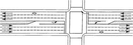
FIGURE 2.72 Common transition for concurrent HOV lanes. (From Guide for the Design of High Occupancy Vehicle Facilities, American Association of State Highway and Transportation Officials, Washington, D. C., 2004, with permission)

Computer-Aided Design and Drafting (CADD)

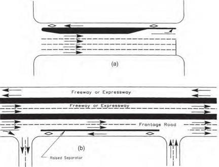
FIGURE 2.73 Typical contraflow HOV lane arrangements. (a) Right curb lane. (b) Left curb lane. (From Guide for the Design of High Occupancy Vehicle Facilities, American Association of State Highway and Transportation Officials, Washington, D. C., 2004, with permission)

display using the centerline of the plan view along with its associated elevation. Although vertical curves consist of a series of closely spaced points in a drawing, they take on the appearance of a “curve” to the viewer. In a cross-section view, the eleva­tion component of the point is shown along with its offset reference to the centerline. The view generated is one in which a “slice” of the roadway is taken as it would look if you took a perpendicular plane to the driver and lifted a section of the road up to see it. In the world of CADD, all these points are three-dimensional and yet have been used, as described above, to generate three different combinations of two-dimensional draw­ings. These two-dimensional drawings make up the majority of the sheets in a set of highway construction plans. The value of CADD is that the points are entered only once, by a described alignment or profile or cross slope in a cross section, and yet have been recalled in numerous applications throughout the plans—whether in developing final cross sections, earthwork calculations, intersection details, drainage designs, etc. CADD software allows the assignment of “names” to various sets of points, such as the centerline of a roadway or the boundary of a property. It also can assign points that are closely associated, if not connected, to a group called a layer or level in the CADD drawing file. One such layer may contain points for a bridge, or even subdivided into layers for bridge deck, bridge abutment, bridge pier, etc. Other layers can be used for hydraulics, lighting, signals, or signs. The assignment of points to layers is limited only by the storage assignment capability of the software and the capacity of the computer memory itself, which far exceeds that required for most projects. The following sec­tions describe the components of a basic set of highway plans, without reference to CADD applications. However, the end product can be completely produced in the CADD environment.

Site Clearing

Although it is more convenient for a contrac­tor to build on a site without obstacles such as trees, native vegetation, and boulders, some but not all contractors will go to great lengths to preserve as much natural vegetation and as many other landscape features as possible. Do not assume that the preservation of your site will be a priority of the same magnitude for a contractor as it will be for you. To clarify your desires and the contractual obligations of the contractor in this regard, you can formalize site preservation intentions by stating them as part of your contract.

Here is an example of site specifications created for the purpose of preserving the nat­ural features of the site and preventing pest in­festations as a result of the clearing process.

It is the owner s intention to preserve the nat­ural vegetation and land features of the site to the greatest extent possible.

• The owner and architect shall approve the site layout prior to the digging of the foot­ings.

• Topsoil and large boulders shall be stock­piled for future use.

• All trees designated for removal from the building site are to be marked for review by the owner or architect.

• All tree stumps and dead foliage shall be fully removed from around and under the

building site and disposed of offsite so they do not attract termites and other pests.

• The owner and architect shall determine which trees are to be transplanted or maintained during construction.

• The construction area and access to it shall be as small as is reasonable to facili­tate construction of the home. This area is to be clearly demarcated and roped off to prevent any destruction of natural terrain outside the area by construction vehicles.

Grading

Many mold problems originate with poor drainage around the building perimeter, which can cause water to puddle against the building and sometimes to seep inside. Al­though less prevalent in dry climates, mold is still a serious health threat, especially in flat – roof construction where canales or scuppers are used for roof drainage and erosion around the discharge is common. An adequate roof overhang will be the first line of defense in keeping water away from the building enve­lope. Good site grading will be the second line of defense and a perimeter drainage system in combination with stem wall dampproof­ing as described in Division 7 will constitute the third component of a comprehensive rain­water management plan. The following speci­fication for surface water runoff management is recommended: [4]

• All canales, scuppers, and downspouts shall have splash blocks and an adequate drainage path away from the building.

Soil Treatment

Sometimes the soils under brick walkways, under interior brick pavers, surrounding the structure, or under the structure itself are treated with insecticides or herbicides. This practice should be avoided. Many people have become sensitive to very low levels of pesti­cide exposure. Children are especially vulner­able. Some harmful agents will remain potent long after the building is gone. Where soil treatment is mandated or otherwise unavoid­able, we recommend the use of boric acid, dia – tomaceous soil, or other least toxic measures. (Refer to the section on integrated pest man­agement in Division 10.) You may wish to specify the following:

* Do not treat soil with manufactured chemical treatments.

* Treat sand surfaces under floors and brick or stone walkways with diatomaceous soil. Inhaling dust from diatomaceous soil is hazardous and proper precaution should be used during application.

* Use barrier cloth under exterior walkways to prevent weed overgrowth.

Pavement

Petroleum tar, which is the main component of asphalt or “blacktop’ paving, is carcino­genic and should be avoided. Not only does it emit harmful vapors during installation but it also will volatilize when heated by the sun. More healthful options include concrete slab, concrete or brick pavers, and paving stone or gravel over a well-drained and compacted base.

The following products are innovative ways to stabilize a road base without the use of asphalt or concrete paving:

• NaturalPAVE XL Resin Pavement: A combination of nontoxic, environmentally friendly organic and inorganic resin ma­terials that creates a high – strength pave­ment.

• Perma-Zyme: A biodegradable and envi­ronmentally safe road stabilization enzyme product that works by lowering the surface tension of water, promoting penetration and dispersal of moisture. This causes hy­drated clay particles to fill voids in soil so that it forms a tight, dense, and permanent stratum.

• Stabilizer: A colorless, odorless psyllium – based concentrated powdered soil additive for dirt or crushed stone surfaces. Stabi­lizer binds and flocks aggregate screenings to provide a firm natural surface for path­ways, trails, and driveways.

Where asphalt paving already exists or is the only paving option available AFM DynoSeal Driveway/Asphalt Sealer may be used. It is a low-odor elastomeric sealer and top coat­ing for asphalt surfaces that helps to reduce the outgassing and odors generated by new asphalt.

Further Reading

International Institute for Bau-Biologie & Ecology. Home study courses, online study, and seminars. PO Box 387, Clearwater, FL 33757,727-461-4371, buildingbiology. net.