HIGHWAY CONSTRUCTION PLANS

2.14.1 Plan Preparation

The purpose of a set of highway construction plans is to delineate the proposed work with sufficient design details, supplemented with notes, calculations, and summary of quantities, so that it can be clearly and uniformly interpreted by engineers and con­tractors (Ref. 8). Sufficient data must be provided to enable the contractor to make an intelligent bid and to perform the work as intended. Clarity, completeness, and

HIGHWAY CONSTRUCTION PLANS

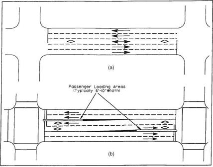
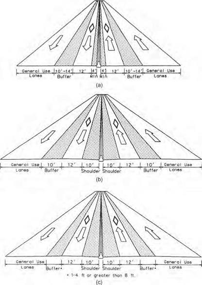
FIGURE 2.70 Examples of median HOV lanes for buses. (a) Reversible lanes for express buses. (b) Two­way lanes for local buses. Conversion: 6 to 10 ft = 1.8 to 3.0 m. (From Guide for the Design of High Occupancy Vehicle Facilities, American Association of State Highway and Transportation Officials, Washington, D. C., 2004, with permission)

conciseness are essential so as to avoid misinterpretation. Unnecessary details should be avoided.

The original tracings serve as a permanent record of the project. They must be prepared on a material acceptable to the agency responsible for maintaining the plans as a record. A currently widely recommended material is the polyester film Mylar with a thickness of 4 mil (3 mil minimum), double – or single – (top side) matted. The surface should not be highly reflective. Only black ink should be used, although grid lines may be colored. Materials that are usually not acceptable include negatives, sepias, vellum, old sheets, dark background, pencil, paste-ons, stick-ons, or bond paper. Original tracings are usually about 22 by 34 in (559 by 864 mm). The designer should prepare the plans keeping in mind that the drawings will most likely be reduced to quarter size (i. e., 11 by 17 in or 280 by 430 mm) prior to distribution.

More and more agencies are switching over to an electronic plan submission. With the overwhelming use of computer-aided design and drafting (CADD) applications, many agencies, large and small, are expressing a preference for plans developed by CADD software. Although paper prints are still necessary as part of the plan develop­ment and construction process, the official filing of Mylar or similar media is being replaced by filing of computer disks that contain design files, including images of plan sheets that can be easily viewed on screen or printed as necessary.

HIGHWAY CONSTRUCTION PLANS

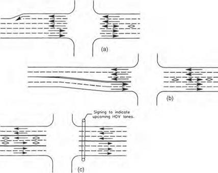
FIGURE 2.71 Typical transitions for median or center lane HOV. (a) With reversible HOV lane and outer transition. (b) With reversible HOV lane and inner transition. (c) With two one-way HOV lanes. (From Guide for the Design of High Occupancy Vehicle Facilities, American Association of State Highway and Transportation Officials, Washington, D. C., 2004, with permission)

Arterial Design Considerations

There are two general categories of HOV lanes for use on surface arterial streets: (1) those which assign exclusive use of designated lanes for HOV use and (2) those which give

Arterial Design Considerations

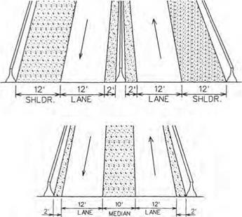
FIGURE 2.63 Cross sections for high-occupancy-vehicle two-way separated lanes on separated roadway. Conversion: 1 ft = 0.305 m. (From Guide for the Design of High Occupancy Vehicle Facilities, American Association of State Highway and Transportation Officials, Washington, D. C., 1992, with permission)

preferential treatment or special privileges to HOVs through traffic control measures. The first category includes concurrent and contraflow reserved lanes, reversible median or center lanes, and streets devoted to HOV use. The second includes such measures as traffic signal preemption systems for buses, and special traffic provisions that allow HOVs to make turns or other maneuvers that are prohibited for other traffic.

Regardless of the type of treatment, the geometric design and traffic control features should accommodate all vehicles that might ultimately use the HOV lane. Since the primary vehicle type using the urban HOV lanes will be buses, special consideration should be given to designing for the vehicle’s dimensions and turning pattern.

Figure 2.70 shows two examples of center lane HOV use. Note the location of passenger loading areas in Fig. 2.70b. The advantage of a center HOV lane over other schemes is that it can be made reversible. Figure 2.71 shows various ways these HOV center lanes are developed.

Figure 2.72 shows the more commonly seen concurrent HOV lane developed in the curb lane of an urban street. The advantage of this type of HOV lane is that it is the simplest and least costly to implement. This usually involves only changing signs and pavement markings and coordinating traffic signals.

Contraflow HOV lanes may be used on one-way or two-way streets. On one-way streets, the HOV lane may be either the right or the left lane, while on two-way streets it can be either the right lane or the inside lane adjacent to the median or centerline of the arterial street. Two examples of contraflow lanes are shown in Fig. 2.73.

Arterial Design Considerations

FIGURE 2.64 Connection of HOV terminal mainline lanes to freeway median with flyovers. (From Guide for the Design of High Occupancy Vehicle Facilities, American Association of State Highway and Transportation Officials, Washington, D. C., 2004, with permission)


Подпись: 205Arterial Design Considerations

——— I —

LANE-REDUCTION TRANSITION SIGNING

FIGURE 2.65 Connection of HOV terminal mainline lanes to freeway median with slip ramps. (From Guide for the Design of High Occupancy Vehicle Facilities. American Association of State Highway and Transportation Officials, Washington, D. C., 2004, with permission)

BUSES AND
CARPOOLS
ONLY

6 AM-9 AM V MON-FRI


MOV PAVEMENT MARKING AND SIGNING NOTES


N0 1 LEFT TURN

7-9 AM 4-6 PM

NO

LEFT

TURN

6-9 AW MON-FRI

AUTOS WITH TRAILERS TRUCKS

EXCEPT 3USES AND CARPOOLS

PROHIBITED

MON-FRI

XoR MORE

R44E3


Arterial Design Considerations

R86


10.

11.


Подпись: 206

12.


DETAIL ‘A1

(See Note 9)


X Use appropriate numeral to indicote the number of persons required for a carpool.


Arterial Design ConsiderationsArterial Design Considerations

Arterial Design Considerations

FIGURE 2.67 Contiguous concurrent HOV lanes. (a) Before adding HOV lanes. (b) After adding HOV lanes. (c) Alternative for HOV lanes with shoulders. Conversion: 1 ft = 0.305 m. (From Guide for the Design of High Occupancy Vehicle Facilities, American Association of State Highway and Transportation Officials, Washington, D. C., 2004, with permission)

Arterial Design Considerations

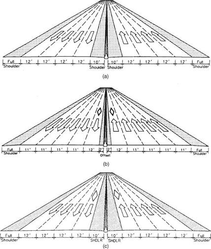
FIGURE 2.68 Examples of concurrent HOV lanes with buffer separation. (a) Without shoulders. (b) With 10-ft-wide buffers. (c) With other buffer widths. Conversion: 1 ft = 0.305 m. (From Guide for the Design of High Occupancy Vehicle Facilities, American Association of State Highway and Transportation Officials, Washington, D. C., 2004, with permission)

Arterial Design Considerations Подпись: Shoulder
Подпись: 10’ Shoulders Desirable
Подпись: Shoulder
Подпись: I 12/ I ■ 2 ^ Full
Подпись: -*4‘ Minimum Shoulders

Arterial Design ConsiderationsFlexible Posts or

Подпись: Shoulder Arterial Design Considerations Arterial Design Considerations Подпись: Shoulder

Movable Barrier

Подпись: the normal flow lanes increasing the contraflow Подпись: an Подпись: width and

Cones or flexible posts in predrilled holes may be moved toward

providing an additional shoulder where a minimum inside shoulder exists. If cones are used they should be deployed with the traffic

Подпись: bufferflow and removed against the traffic flow for safety.

Подпись: lane design is not employed, the posts will be placed along the

lane line in the gaps between the traffic stripes

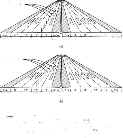
FIGURE 2.69 Examples of contraflow HOV lanes. (a) With posts on lane line and no buffer. (b) With posts in lane providing buffer. Conversion: 1 ft = 0.305 m. (From Guide for the Design of High Occupancy Vehicle Facilities, American Association of State Highway and Transportation Officials, Washington, D. C., 2004, with permission)

Techniques FITTING SHEATHING

SOMETIMES A LITTLE extra persuasion is needed to unite tongue-and-groove sheathing panels. Have one person stand on the edge of the sheet and hold it flat and snug against the previous row of sheathing. Another person can lay a scrap of 2x (to protect the groove from damage) against the sheet and hit it with a sledgehammer. A couple of licks should bring the two sheets together. If not, check the edge for damage or for an obstruction that may be holding the two sheets apart.

Techniques FITTING SHEATHINGCOAX PANELS INTO PLACE. A couple of good wallops with a sledge will usually seat even an ornery Sheet Of tongue-and-grOOVe Sheathing. [Photo by Roe л. Osborn, courtesy Fine Homebuilding magazine, The Taunton Press, Inc.]

line. On one side of the building, measure in 48УІ in. at each end and snap a chalkline across the joists. The first row of sheathing is laid and nailed directly on that line. Getting this first row straight makes it easier to lav all sub-

O і

sequent rows.

Подпись: ,w?Lay down a full К-in. bead of construction adhesive on the joists beneath each sheet just before setting it in place (see the photo at left). This makes the floor structurally stronger and cuts down on squeaks in the future. Lay the first sheet with its grooved edge right along the control line, with one end on the center

SHEATHING MUST BE GLUED AND NAILED. Use a caulking gun to apply a bead of construction adhesive to the joists’ top edges before installing the floor sheathing. The adhesive strengthens the floor and helps reduce squeaking in the future.


Techniques FITTING SHEATHINGTechniques FITTING SHEATHING

Подпись:

ofa rim joist and the other end landing mid-joist—8 ft. to the left or the right. If a sheet doesn’t fall on the center ofa joist, try pushing the joist over a bit. If this can’t be done, mark the sheet to length so the edge will land mid-joist, then snap a chalkline and cut the sheet. Finish sheathing the first row before moving on to the second one.

The second row of sheathing is installed much like the first, except that you begin with half a sheet (a 4-ft. by 4-ft. piece). This stag­gers the joints, which makes for a stronger floor. If you re building in a humid climate, leave about % in. between the ends and the edges of the sheets to allow for expansion.

This gap can be gauged by eye or by using an 8d nail as a spacer. The 14-in. gap between sheets means that vou will have to trim an end now and then so that each sheet lands squarely on a joist. Some manufacturers make sheets % in. short to allow for gaps and elimi­nate the need to cut sheets.

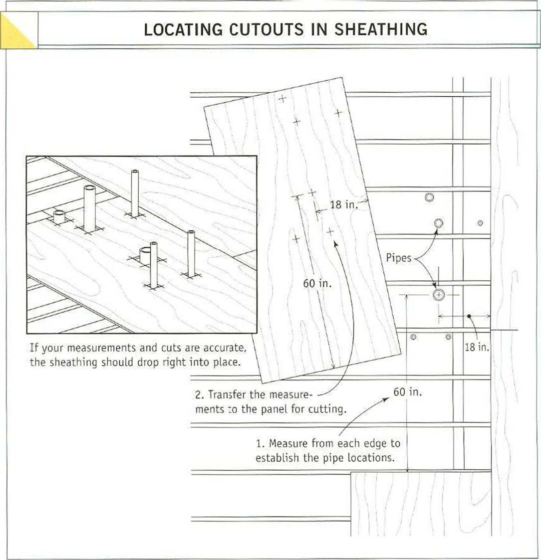
When plumbing pipes are installed before the sheathing, vou must lav out and cut holes in the sheathing. The easiest wav 😮 lav out these cuts is to measure from the edges of sheathing already in place to the center of the pipe, then transfer those measurements to the sheet that the pipe will go through (see the illustration on the facing page). Cut the holes somewhat larger than the pipes, using a circu­lar saw to make a plunge cut, as shown in chapter 2. This makes it easier to lift the sheet and set it in place over the pipes. Later, seal the holes well to keep cold or moist air from entering the living space from below.

Secure the sheathing to the joists with 8d nails

When the last panel in a course of sheathing extends beyond the rim joist, cut it flush with

the rim joist before nailing it down (see the photo above). The typical railing schedule for sheathing is 8d nails 6 in. o. c. around the perimeter of the building and at joints between the sheets and 12 in. o. c. in the field (the middle of the sheets). It’s best to nail the sheets soon after laying them, especially in hot weather, so that the adhesive doesn’t have a chance to set before the sheet is pulled fast to the joists. If necessary, snap chalklines across the panels to show the joist locations for nailing.

An efficient method is to have one team lav

4

sheets and tack them at their four corners, then have another team follow behind, nailing off the sheets completely. In many areas of the country carpenters use rough-coated, hot- dipped galvanized nails or nails with grooves cut in them (ring-shank nails) to ensure that the sheathing stays firmly secured to the joists.

Walls Create Sp

Finalizing the Changes in the Aggregate Mix

As a result of the actions undertaken during Stages 1-4, the present mix is distin­guished by a very high proportion of coarse particles (the strong skeleton) and the maximum discontinuity of gradation allowed by the gradation curves of SMA 0/11 according to ZW-SMA-2001. The share of the coarse aggregate fraction was fixed all the time at the level of 75% (m/m). Keeping in mind the impact of the size of coarse aggregate fraction on the content of voids and binder, specimens can be prepared and then tested to check their characteristics, and finally some final refinements to the fraction in question can be made.

But there is still a question, is it a good SMA mixture? Let us compare our newly designed very coarse SMA to the German recommendation and the 30-20-10 rule.

THE STANDARD PLUMBING CODE

The Standard Plumbing Code provides a sizing example in their codebook. The Standard Plumbing Code, the BOCA code, and the International Plumb­ing Code have joined together and your local code office may have any vari­ation of these three codes in effect, so check your local codes carefully. A fac­tory is the building chosen for their sizing exercise. The instructions provided in their sizing example and explanations is good. By using the tables provided and the formulas given, you can size the water distribution system for the building with minimal stress.

The responsibility of sizing a large water system may never be placed on your shoulders. Architects and engineers will probably design most of the sys­tems that you install in large buildings. But, it does pay to understand the con­cepts behind sizing a system. Work through the examples I’ve provided above until you are comfortable with the procedure. Once you get the hang of it, sizing a system is not terribly difficult.

Tool Talk MAKING A BLOCK-CUTTING TOOL

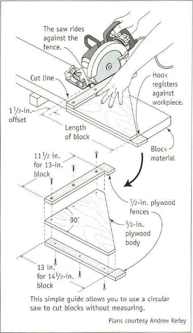
MANY CARPENTERS CUT BLOCKS with a


chopsaw, which is fine if you have one. But there is another easy way to cut blocks. Try making a simple block-cutting tool to use with a circular saw. Once you have the guide, simply hook it on a 2x and make the cut along the edge.


Л > ‘Її

.’■m

Щ


MAKE A JIG TO CUT BLOCKS QUICKLY. This simple jig can be made from scrap in just a few minutes. It eliminates all measuring and marking, which saves a great deal of time when cutting blocking.


Tool Talk MAKING A BLOCK-CUTTING TOOLTool Talk MAKING A BLOCK-CUTTING TOOL

Tool Talk MAKING A BLOCK-CUTTING TOOL

job site, as I-joist width varies from manufac­turer to manufacturer. T he most common width for residential 1-joists is 9’/ in., so you can cut blocking from scrap pieces of I – joists or from 2×10 lumber. Cut the blocking to lit snugly between the chords of adjacent I – joists, and nail the blocking to the chords.

When nailing blocking between joists, it’s best to begin at one end of the house and sim – plv work your way toward the opposite end. Sight down the length of the first joist (the one closest to the rim joist) and make sure it is running straight. Measure the first joist space and cut the block to length. Set the block on edge over a girder or a crib wall. Drive two 16d nails through the rim ioist into the block and two 16d nails through the floor joist into the block. Next, angle a I6d toenail through both sides of the joist into the girder. Nail lapping joists together with two I6d nails. Sink one 16d toenail through each joist into the girder and angle a 16d toenail down
through the block at each end into the joists they span.

Once you have a few blocks nailed in place, use a tape measure to make sure the joists are maintaining an accurate o. c. layout so that the sheathing will land mid-joist. 11 necessary, cut the blocks a bit short or long to maintain accurate spacing.

In many parts of the country, rough plumbing and heating ductwork are installed before the floor is sheathed, so be sure to check with those contractors before sheathing. Also, find out whether you need a floor joist inspection before you install the floor sheathing.

STEP8 Install the Floor Sheathing

Before plywood and OSB were readily avail­able, we sheathed floors with softwood 1x6s that were cut and nailed diagonally across the joists. To make the joints between the 1×6
boards, the ends of each board were cut at a 45-degree angle. Frequently, the 1×6 lumber was of poor quality and had large knots. I still have scars on my lower legs from breaking through subfloors while working on job sites decades ago. The sheathing panels we use todav are much better than 1×6 boards—vet

4 4

another improvement over how houses were built in "the good old days.”

Sheathing with 4xtS sheets of tongue-and – groove plywood or OSB is not difficult, though the sheets can be awkward to handle. Carry them with a partner, if necessary, and take care not to damage the tongues or the grooves, which can make X more difficult to fit the sheets together. Be sure to use exterior – grade, л-in.- or %-in.-thick sheathing.

Snap a line to lay out the first sheathing course

Подпись: Helping HandПодпись: That empty feeling. When installing sheathing, you can feel when a nail doesn't hit a joist—it goes in too easily. Driving a fresh nail to the left or right of the dud usually results in solid contact. When laying out long rows of 4×8 sheathing, its best to start from a control, or reference,

Doors, Windows, and Skylights

Doors, windows,

to do a lot. They must be solidly attached yet mov­able, let light in while keeping rain out, admit guests but deny drafts. Because these units are so complex, it’s impossible to shoehorn everything one might say about them into one chapter. You’ll find more about flashing in Chapters 5 and 7; more on adding openings to exterior walls, replac­ing rot, and structural carpentry in Chapter 8; and more on installing interior casing in Chapter 17.

This chapter begins with installing interior doors—among the last things you’d do in a renova­tion—but a task so similar to hanging exterior doors that these two procedures belong side-by-side.

Ordering Doors: An Overview

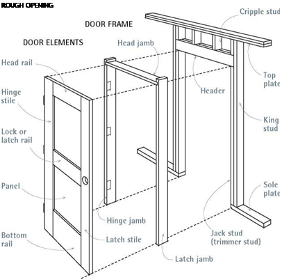
Door frames consist of several pieces: two side pieces, or sidejambs, and a head jamb (or frame head) running across the top; exterior doors also have a sill spanning the bottom. (The sill may also
have a threshold, but more about that later.) Jambs are further distinguished by the hardware they bear: The jamb on which the door is hung is the hinge jamb; the jamb that receives the latch is the latch jamb (also called strike jamb or lock jamb).

From door to door, parts names are similar. On a common frame-and-panel door, the thicker vertical elements are called stiles; hence, hinge stile and latch (or strike) stile. Horizontal ele­ments are called rails. Glass panes in French doors are called lights, and the wood strips between lights are called muntins. Consider the following factors when ordering doors.

Interior vs. exterior. Exterior doors are generally thicker (154 in. vs. 158 in.), more expensive, more weather resistant, and more secure than interior doors. Because they must withstand weather, exterior doors may have water – or UV-resistant finishes and are often insulated and weather – stripped. Don’t use doors designed for interiors outside—they won’t last.

If water is a house’s greatest enemy, cap (head) flashing may be one of its greatest allies, for it diverts water around doors, windows, and skylights, thus preventing leaks at the top of the unit. Building paper and stucco will overlay the top flange of this cap flashing.


image185

Подпись: I Door, Door Frame, and Rough OpeningПодпись: ROUGH OPENING image187Prehung. Prehung (preframed) doors come fit­ted to a frame, with hinges mortised into a jamb. Ordering prehung doors can save huge amounts of time. However, if doorways are already framed, specify unframed doors (see "Hanging a Door to an Existing Frame,” on p. 110).

Knock-down prehung doors arrive with the frame head cut to the correct width and all other parts milled with correct clearances around the door, but the parts are not assembled. This allows you to trim the jambs down to the right length for your flooring and threshold heights. Suppliers will cut exterior sills to fit if you ask them to, but many contractors prefer to buy sills separately and fit them on site.

Width. Door widths increase in 2-in. increments. When door dimensions are stated as a pair of numbers, width always comes first—for example, 2 ft. 8 in. by 6 ft. 8 in. (this is sometimes abbrevi­ated as 2868).

Standard interior doors are 2 ft. 6 in. and 2 ft.

8 in. wide. For doors leading to busy hallways, architects often specify 2 ft. 10 in. or 3 ft. 0 in. If you need access for wheelchairs, order special doors 3 ft. 6 in. wide. Narrow doors (2 ft. 0 in. to 2 ft. 4 in.) are available for half baths and closets; and narrower ones (1 ft. 4 in. to 1 ft. 10 in.), for linen closets and such.

Standard exterior doors are 3 ft. 0 in. wide, though side doors are sometimes 2 ft. 8 in. or 2 ft. 10 in. wide. Again, wheelchair-access exterior doors need to be 3 ft. 6 in. or 4 ft. 0 in. wide.

Freeway Design Considerations

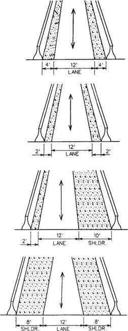
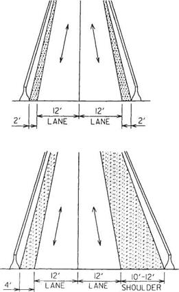
There are three types of HOV lane patterns—separated lanes, concurrent flow lanes, and contraflow lanes. Regardless of which pattern is chosen, consideration should be given to traffic operations at interchanges and on-ramps, pedestrian access to on-line stations, the availability of parking areas at or near the stations, and the possible use of HOV lanes during freeway maintenance of traffic operations. Design speeds should generally be the same as for the mainline facility. Recommended lane and shoulder widths can be seen in the next group of referenced figures (Figs. 2.61 through 2.66).

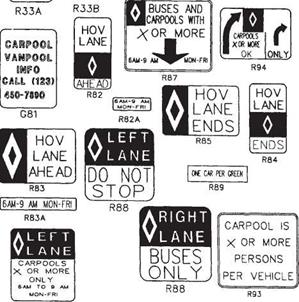
A separated HOV lane may be located in the median or on the outside of the general lanes, or follow an independent alignment. See Figs. 2.61, 2.62, and 2.63 for examples of cross sections. Figures 2.64 and 2.65 show two examples of how separated HOV lanes tie in with the general main lanes of travel. Figure 2.66 shows sample signing and pavement marking used in connection with HOV lanes. Note the diamond symbol that signifies an HOV lane.

Concurrent flow lanes are located adjacent to traffic lanes and are not physically sep­arated from them. Figures 2.67 and 2.68 are examples of typical sections for concurrent HOV lanes.

Freeway Design Considerations

FIGURE 2.61 Cross sections for high-occupancy-vehicle single lane on separated roadway; one-way or reversible. Conversion: 1 ft = 0.305 m. (From Guide for the Design of High Occupancy Vehicle Facilities, American Association of State Highway and Transportation Officials, Washington, D. C., 1992, with permission)

Freeway Design Considerations

FIGURE 2.62 Cross sections for high-occupancy-vehicle double lanes on separated roadway; one-way or reversible. Conversion: 1 ft = 0.305 m. (From Guide for the Design of High Occupancy Vehicle Facilities, American Association of State Highway and Transportation Officials, Washington, D. C., 1992, with permission)

Contraflow lanes provide an exclusive lane for HOVs traveling in the peak direction by removing a lane from service in the off-peak direction. These may be used in areas where traffic volumes in the off-peak directions are such that the level of service is not seriously affected. Some kind of buffer zone or device is strongly recommended for obvious safety considerations. Figure 2.69 provides examples of cross sections for contraflow HOV lanes.

EXAMPLES FROM THE DEMONSTRATION PROJECTS

The accompanying illustrations show some site plans from demonstrations in the’Affordable Housing Program. The sites vary greatly in shape and in their physical characteristics.

However, each of the plans represents a creative relationship to the existing land. Densities vary from five units per acre for the least dense single – fam’ily detached homes to 17.4 units per acre for the most dense single­family attached homes.

Local land use restrictions, and the degree to which local officials were willing to waive or modify certain existing zoning or code restrictions as requested by the developer, varied with each site. However, in all the affordable housing demonstrations, public officials and developers worked together with a high degree of cooperation to achieve affordability.

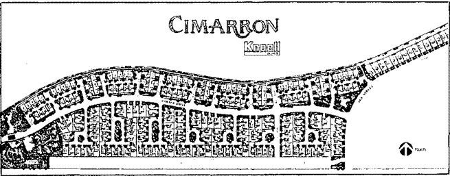
Подпись: Phoenix, ArizonaThe Cimarron development is situated on a narrow 38-acre plot of land which Rnoell Homes had originally laid out for 149 detached single-family units. After joining the. Demonstration Program, Rnoell redesigned the _ development to add 106 units, bringing the total to 255.
Подпись: Entrance to Cimarron EXAMPLES FROM THE DEMONSTRATION PROJECTS
Average lot size was reduced from 6,000 to 3,600 square feet and density was increased to 6.7 units per acre. The housing mix consists of 107 townhouses and 148 single-family units, ranging in initial (January, 1983) sale prices from $45,000 to $63,000. Reductions in widths of streets, rights-of-way, and sidewalks, subjects which are discussed more fully in an ensuing section, added about five acres to the land available for housing over the original plan.

More than seven acres are devoted to open space which includes retention ponds set in attractive landscaping on either side of the development entrance, other landscaped areas, utility rights-of-way, a jogging course, and common land.

EXAMPLES FROM THE DEMONSTRATION PROJECTSThe original plan for The Park called for the construction of 153 detached and attached units on a 21.9-acre site of approximately triangular shape. This initial plan was both innovative and efficient in terms of land use. _ However, when Phillips Homes joined the Affordable Housing Program, the site was redesigned to increase the number of units to 176, increasing density from 7 to 8 units per acre.

Site plan (after)

EXAMPLES FROM THE DEMONSTRATION PROJECTS


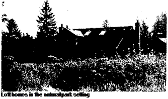
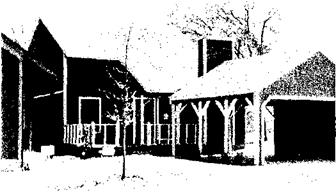
Подпись: Loft homes in the natural park setting Подпись: Boise, IdahoThe housing mix consists of 64 "pinwheel" cottages, 10 zero-lot-line patio homes, 38 townhouses, and 64 quadplex units called "loft homes." Units range in size from 648 to 1,287 square feet. Many large trees were preserved, and a central clubhouse and swimming pool are located in a small park.

Lakewood Meadow, built by Triangle Development Company, is a 52-home project on a triangular 13.3-acre site. The project is part of a 263-acre planned residential community called Lakewood, situated in one of the most desirable residential areas in town.

EXAMPLES FROM THE DEMONSTRATION PROJECTS

Lakewood Meadow demonstrates the feasibility of creating an affordable housing segment in a development whose other homes are more luxurious and expensive. The Affordable Housing segment incorporates such features as smaller lots, narrower streets, sidewalks on one side of the street only, T-turnarounds instead of cul-de-sacs, and roll curbs.

These features enabled the developer to add five building lots to the Lakewood Meadow segment while retaining amenities and architectural style that characterize the substan­tially more costly homes in the balance of the Lakewood development.

Lots in Lakewood Meadow are approximately 6,000 square feet, and homes range from 1,100 to 1,700 square feet in living area.

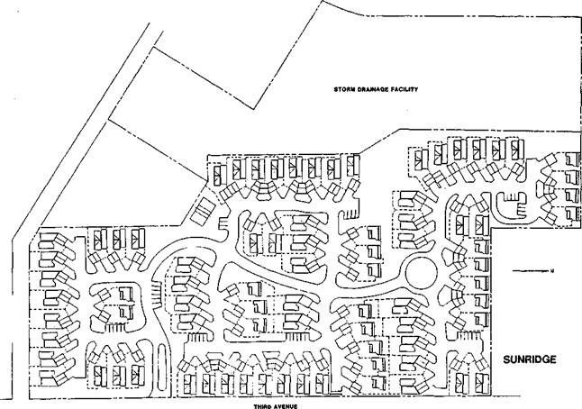
Sunridge is built on a 20.4-acre site of which about 6 acres along a stream were dedicated to the city for a stormwater detention system, and another 2.4 acres is consigned to commonly-owned space spread through­out the development. Eighty-one units were built on the remaining 12.2 acres, providing a density of 6.6 homes per acre.

EXAMPLES FROM THE DEMONSTRATION PROJECTS

Подпись: McGILL AVENUE Подпись: Everett site plan
EXAMPLES FROM THE DEMONSTRATION PROJECTS

All of the homes have a southern exposure, and the house designs are oriented toward passive solar heating. All homes are zero-lot-line, and yards are fenced. Garages for all homes are sited at an angle to add interest to the streetscape.

Mature trees were preserved on the site wherever possible, and the development has been extensively landscaped. Three types of homes were built ranging from 1,076 to 1,624 feet in living area.

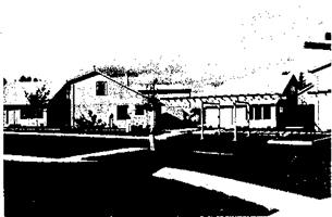
Подпись: Portland, OregonEXAMPLES FROM THE DEMONSTRATION PROJECTSNorth Meadow Village occupies a triangular 6-acre site. Density is 9.7 units per acre. Homes in the develop­ment are arranged in pinwheel clusters.

Подпись: Portland land plan
With the cooperation of municipal officials, the developer utilized reduced lot sizes, narrower streets and rights-of-way, smaller setbacks from the street, and common, covered off-street parking to make more land available for housing. Additional land was-freed for home construction through use of an innovative storm­water drainage system employing three on-site dry sumps.

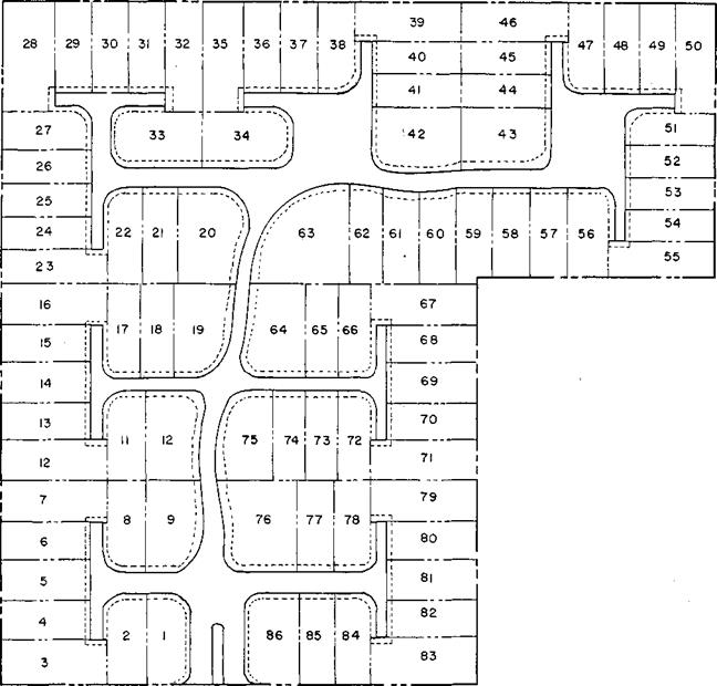
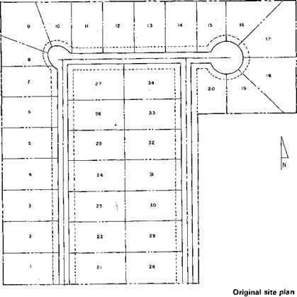
Подпись: Tulsa, OklahomaEXAMPLES FROM THE DEMONSTRATION PROJECTSInnovare Park is constructed on a panhandle-shaped 7.98-acre site. The original site plan was for 34 detached units in a traditional grid pattern with straight-run streets. After joining the Affordable Housing Program, Hood Enterprises redesigned the site to accommodate 86 detached units.

The revised plan utilizes one collector street with short feeder streets ending in T-turnarounds. The smallest lots are 2,250 square feet, but most are 35×80 feet, or 2,800 square feet. Houses are placed close to the lot line with a minimum 5-foot clearance between units.

EXAMPLES FROM THE DEMONSTRATION PROJECTS

EXAMPLES FROM THE DEMONSTRATION PROJECTS

EXAMPLES FROM THE DEMONSTRATION PROJECTS

Revised site plan

EXAMPLES FROM THE DEMONSTRATION PROJECTS

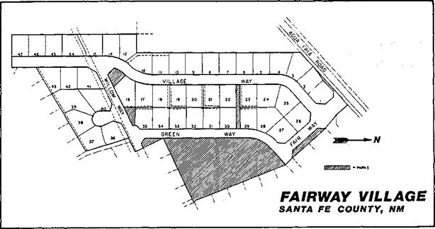
Santa Fe, Fairway Village, built by Walton New Mexico Chapman Builders, is a 154-home project on 31 acres just outside the city limits in an area planned for future annexation. Homes are sited in a pinwheel arrangement rather than in traditional rows. Varying setbacks create interesting front yards and streetscapes.

The pinwheel siting creates a feeling of community and enhances outdoor privacy. A 1.5-acre park with recreational equipment provided by the builder completes the village.

Operational Considerations

Management of HOV facility operations may be accomplished by a range of techno­logical and personnel means. Minimum control may consist of passive signing and delineation. Maximum control may involve sophisticated surveillance, vehicle detection with computer integration, and dynamic, real-time signing or delineation.

A determination of the level of vehicle restriction must be made on the basis of traffic characteristics and how much the HOV lane is used. Restricting use of the HOV lane to vehicles with three or more passengers (3 + ) may give the appearance that the lane is underused. On the other hand, restricting the lane to vehicles with only two or more passengers (2 + ) sometimes results in lane utilization approaching capacity. The best rule of thumb is to start with the 2+ restriction, and go to the 3+ restriction when the level of service of the HOV lane is approaching capacity.

A proper level of enforcement is necessary to ensure that the HOV lane will operate efficiently. Absence of enforcement defeats the purpose of the lane, since single­passenger vehicles will see no need to stay out of the lane. Detection and apprehension of violators, issuance of citations to violators, and effective prosecution of violators are essential.

The hours of operation that an HOV lane is in effect are also an important consider­ation. Twenty-four-hour operation is preferred over peak-hour operation, simply because there is less chance for driver confusion and violations tend to be lower.