Suction

Soil suction or capillary pressure head can be measured either in the laboratory in an undisturbed sample of soil or directly in the field. Soil suction or total suc­tion consists of the matric suction and the osmotic suction. Their magnitudes can range from 0 to 1 GPa (Rahardjo & Leong, 2006). Today no single instrument or technique exists that can measure the entire range with reasonable accuracy. Suction measurement instruments can only measure suction up to about 10 MPa. In the highway environment soil suction in the low range (0-100 kPa) or the mid range (100kPa-1 MPa) is of most concern. There are different measurement tech­niques depending on which component of suction one wants to measure, matric or total. Usually in geotechnical engineering it is the matric suction that is measured. Table 3.2 summarises techniques for measuring suction in terms of approximate measuring range and applicability in the laboratory or field (Lu & Likos, 2004; Rahardjo & Leong, 2006). As it is generally not necessary to take osmotic suc­tion into account in routine geotechnical engineering practice, only the main in-situ methods for measuring matric suction are referred to. They include tensiometers, thermal conductivity sensors and contact filter paper techniques.

Direct measurement of suction in aggregates is more difficult than in finer grained soils as it is difficult to establish an effective contact between the measuring de­vice and the pore space in the aggregates. In aggregates with a high proportion of fines, this may be achievable. Alternatively, indirect measures such as discussed in Chapter 2, Section 2.9, can be employed.

SHIMMING THE FRAME

Plumb the hinge jamb first, using a 6-ft. level for accuracy. Or you can hang a plumb bob from a nail in the top of the jamb, as shown in the left photo on p. 102, and measure from the plumb line. When the jamb is plumb, all measurements from the jamb to the line will be equal.

1. If jack studs (trimmer studs) on either side are square to the face of the opening, pair shims so that their tapers alternate, creating a flat sur­face behind the jamb. However, if jack studs are twisted, you may need to insert an odd number of shims to build up the low edge of the twisted stud. Adjust shims in and out, constantly check­ing for plumb and square till both the face and the edges of the hinge jamb are plumb. This takes patience. Most installers start shimming behind the top hinge.

Interior doors are commonly shimmed with three pairs of shims along each jamb: behind the two hinges and halfway between them. However, to prevent jambs from twisting should the door fly open suddenly, many carpenters also shim behind the top and bottom corners of each side jamb.

2. After checking that the frame head is level, secure the latch jamb. Margin that jamb, and tack it in place. At this stage, most carpenters rehang the door to the hinge jamb so they

can eyeball jamb clearances to the door. Mill specs vary, but there’s usually an ‘/-in. gap along the hinge jamb and Иб in. to ‘A in. of clearance along head and latch jambs.

Shim at least three points along the latch jamb; one shim point should be directly behind the strike-plate location. If the latch jamb bows into the opening, add nails or screws to draw it back toward the jack stud. Check for margin,

Подпись:Подпись: If you must reduce the width of a door, use a power plane on the hinge stile of the door. Planing down the lock stile is not advisable because locks have specific setbacks from door edges and you'd need to move face bores, too. So, it's far easier to plane hinge stiles.image197Подпись:square, and plumb as you go. Shim up from the bottom of the jamb as needed to create a uniform clearance along the length of the door and at the upper corner.

3. Shim the frame head, inserting a pair of shims at either corner. Caution: If you drive shims too aggressively, you’ll cause the top of the door to bind.

4. This is the last chance to check margins and adjust shims, if necessary. Make sure all clearances around the door are uniform. When the door is closed, it should be parallel with the latch jamb. Once you’ve checked for margin, plumb, level, and clearances all around, secure the frame. Use five pairs of 10d finish nails or trim-head screws: one pair near each hinge, one pair in the middle of the frame, and one pair at each corner. Using a pair of nails or screws at each shimming point will keep the frame from turning.

image199

After planing down the hinge stile, use a small router (laminate trimmer) to mortise the hinge gains deeper. Clamp scrap to the door edge to provide a wider base for the router. You could use a chisel, but a router will get the depth exactly right.

IF THE DOOr HITS THE LATCH JAMB

If the door hits the latch jamb, the frame head may have been cut a little short.

If it’s a very slight amount, you may be able to back out latch-jamb shims and hammer the latch jamb outward, using scrap wood to avoid marring it. But if the door still hits, you may need to rip down the hinge stile slightly to reduce the door’s width. Because holes for locksets are backset exactly from the edge of the door, don’t rip down the lock stile. It’s far easier to remove the hinge butts, use a power plane to trim the hinge stile, and then recut the hinge mortises an equal amount.
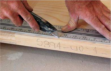
Подпись: FINAL TOUCHES Now you're in the home stretch. 1. Install the lockset in the door, mortise the strike plate into the latch jamb, and shut the door. With the door shut, make light pencil marks on the latch jamb to indicate the door edge when closed. Then place the doorstop back Иб in. (about the thickness of a dime) from those marks. The door and its stops should not quite make contact if they're yet to be painted. Evenly space five 4d finish nails to attach the stop to the latch jamb. 2. Set all nails with a nail set (or turn screws slightly below the surface) and fill holes. If you'll be painting, fill the holes with spackling compound; if using a clear finish, fill with wood dough or a stick-type filler. 3. Using a sharp mat knife or a Japanese saw, score the shims along the wall, tight to the frame. Trimming Doors When your door swings open, it should not "pattern" your carpet or abrade the finish floor. If it does, trim the bottom rail of the door. To register the height of the carpet on the base of the door, slide a flat builder's pencil across the carpet. The pencil, being flat, won't sink into the carpet as much as a round pencil will. Add Vs in. of clearance to that rough line and score the final cutoff line onto the door, using a utility knife drawn along a straightedge. Scoring the door is important, for it prevents vertical grain from splitting and veneer from lifting and splintering. Run the circular saw a whisker below that scored line and you'll get a nice, clean cut. For best results, use a circular saw with a sharp Mastercut® blade, which has a close configuration of at least four fine teeth and a raker to clear chips. Use a straightedge clamped to the door to guide the blade. Clean the saw sole (base plate) well: de-gum it with turpentine (or paint thinner) and steel wool; then rub it with metal-polishing cloth or paraffin to help it glide across the wood. Smooth the cut, and ease the edge with 220-grit sandpaper, sanding with the grain. image200

Score as deeply as you can (shingle butts may take several passes); then snap off the waste.

Don’t try to snap shingles that are too thick, or you may torque the jamb out from the opening. Then install the interior trim (see Chapter 17).

Installing a Basic Exterior Door

Installing a prehung exterior door builds on the information just presented, so if any step is insuf­ficiently explained here, consult the preceding section.

ASSESSING AND PREPPING THE OPENING

Cover finish floors with heavy cardboard or particleboard when installing an exterior door, and cover the work area with tarps to contain the mess.

1. Before ordering the new door unit, meas­ure the height and width of the RO and the thick­ness of the wall; check the jack studs for plumb, the header for level, and corners for square. You can install a squared door frame into an out-of­square opening. But to allow proper shimming, the RO must be at least 1 in. taller and wider than the frame.

2. Next determine the height of the finish floor. In most cases, prehung doors come with a combination sill-threshold already attached, which sits directly on the plywood subfloor. How­ever, some custom exterior doors come with sep­arate sills set flush to the subfloor, which require installing the sills before the subfloor or notching the subfloor and the framing below the subfloor to accommodate the thickness of the sill.

If you need to build up the bottom of the opening to make the new sill the same height as the finish floor, do so now.

3. The bottom of the RO should be level and weather tight. If there’s an overhang to protect the door, just line the bottom of the RO with building paper. If there’s no overhang, install a floor pan across the bottom of the RO. The pan can be as simple as a peel-and-stick flexible membrane applied to the subfloor or, if your region gets driving rains, a prefabricated metal pan (usually aluminum).

Whatever the pan material, fold its ends and back edge up so it will confine any water that gets under the sill rather than soaking the fram­ing, subfloor, or finish floor. Overlap the pan cor­ners and caulk them for good measure. (Make sure the caulk is compatible with the flexible membrane.) Solder or caulk the metal pan seams. Finally, the outer lip of a floor pan should

FITTING SHEATHING

Sometimes a little extra persuasion is needed to unite tongue-and – groove sheathing panels. Have one person stand on the edge of the sheet and hold it flat and snug against the previous row of sheathing. Another person can lay a scrap of 2x (to protect the groove from dam­age) against the sheet and hit it with a sledgehammer. A couple of licks should bring the two sheets together. If not, check the edge for damage or for an obstruction that may be holding the two sheets apart.

Coax panels into place. A couple of good wallops with a sledge will usually seat even an ornery sheet of tongue-and-groove sheathing. [Photo by Don Charles Blom]

FITTING SHEATHINGПодпись: Modify cabinets for wheelchair access. Lower countertops and desk-type openings can make the kitchen much more accessible. [Photo by Steve Culpepper, courtesy Fine Homebuilding magazine © The Taunton Press, Inc.]

Habitat

for Humanity6

HABITAT BUILDS BARRIER-FREE HOMES

Simple, single-story houses are not only less expensive to build but also lend themselves well to barrier-free (handicap-accessible) construction.

In addition to the obvious differences that relate to wheelchair accessibility—wider hallways and doorways, a ramp instead of a stairway at the entryway—many other smaller details help make these homes easier for their owners to use and enjoy.

The key to building or retrofitting a house for wheelchair accessibility is recognizing the modified reach of a seated person. You can start by raising the position of electrical outlets and lowering the height of light switches, closet poles, shelves, and coun­tertops. These easily made alterations help make day-to-day life more convenient for someone in a wheelchair.

Bathrooms and kitchens require special attention. Plenty of strategically placed grab bars are impor­tant; place them around the toilet and in and around the tub/shower. Extra space in the bathroom—so a wheelchair can get in and maneuver around—is es­sential, too. In the kitchen, lowered stovetop, sink, and cabinets help make it possible for someone in a wheelchair to prepare and serve meals and clean up.

Recognizing the increasing need for barrier – free housing, the Knoxville, Tennessee, Habitat affiliate sponsored a contest to design an adaptable, inexpensive, barrier-free house.

Two designs were selected as winners; both are available to any affiliate through Habitat for Humanity International. With the leading edge of the baby-boom population already past 60, more and more of us may come to appreciate housing that’s flexible enough to adapt to our needs a s the years go by.

—Vincent Laurence


perimeter of the building and at joints between the sheets and 12 in. o. c. in the field (the middle of the sheets). It’s best to nail the sheets soon after laying them, especially in hot weather, so that the adhesive doesn’t have a chance to set before the sheet is pulled fast to the joists. If nec­essary, snap chalklines across the panels to show the joist locations for nailing.

An efficient method is to have one team lay sheets and tack them at their four corners, then have another team follow behind, nailing off the sheets completely. In many areas of the country, carpenters use rough-coated, hot – dipped galvanized nails or nails with grooves cut in them (ring-shank nails) to ensure that the sheathing stays firmly secured to the joists.

FITTING SHEATHING

Photo courtesy HFHI/Stefan Hacker

STEP BY STEP


On Beams with a Round Cross-section, or Vigas

Подпись: Fig. 2.6: With rectilinear structures, alternate large and small ends of viga-type joists or rafters. The drawing is exaggerated to make the pointimage16

Many old barns and houses make use of floor joists and rafters that were made from locally grown straight tree trunks. Sometimes the builder would flatten one edge of the timber with an adz, so that roofing or flooring could be more easily nailed to it. In Mexico and the Southwest, exposed vigas (beams of round cross-section) are a common and attractive architectural feature.

Owner-builders today sometimes make use of their own home-grown timbers. They can be taken to a sawmill for squaring, they can be milled in the forest with a portable sawmill, or they can be barked and used in their natural round cross-sectional shape.

While this book is mostly concerned with the use of timbers milled on four sides, the author is in no way opposed to the use of viga-type beams, which can be quite beautiful. Here are some tips with regard to their use.

1. Choose sound straight trees for making vigas.

2. Remove the bark. The easiest time to do this is in the spring, when sap is rising. The greasy sap actually makes barking the wood very much easier, as it forms a slippery layer between the bark and the cambium wood layers. Good tools for barking include a pointed mason’s trowel, a straight hoe, or a peeling spud made from any piece of flat stock metal that has an edge sharpened. Barking at the wrong time of the year, such as autumn, may necessitate the use of a drawknife, which is a lot like hard work.

3. For the purpose of judging the strength of a viga, consider its small end as the sectional dimension. Remember the old saying that a chain is only as strong as its weakest link? This principle is often

appropriate with timber framing, where a mortise and tenon joint can actually reduce the shear strength of beams where they join a post. However:

4. For maximum strength with rectilinear structures, alternate large and small ends on parallel rafters or joists, as per Fig. 2.6. This is different from the weakest link analogy, as the entire floor or roof is distributed over several parallel rafters and alternating weak and strong members lends greater strength to the entire structure. Stronger members assist weaker members.

5. With a radial rafter system, where all the rafters or joists head towards the center, as in our round Earthwood house, put all the smaller ends towards the middle, where they are supported by a large post or a post- and-capital, as per Fig. 4.28. The frequency (space between members) is greater towards the center, so the strength there is naturally enhanced. The big ends are placed at the building’s circumference, where they

help to support the greater planking spans and their resultant loads. Fig. 2.7.

Incidentally, for beams with a round cross – section, like vigas, the section modulus is expressed as S = fTd3/32, or, simplifying constants, S = .09818d3. So, for a beam cut from a tree trunk with a small-end diameter of eight inches, we get a section modulus of.09818(8")3, or 50.27 inches cubed. A beam with a square cross-section, common with timber framing, has a section modulus of S = d3/6. So, for a full eight – by-eight, S = (8")3/6 = 85.33 inches cubed. I find it interesting that an 8" diameter log has so much less bending strength than an eight-by-eight timber. Also, the eight-by-eight is "stiffer." See the section on Deflection.

Fig. 2.7: With a radial rafter system, place the smaller end of the vigas over the center support post.


image17

Installing an Interior Door

There are many ways to hang a door. Thus, the installation sequences that follow occasionally offer alternative methods.

ASSESSING AND PREPPING THE OPENING

Prehung doors usually come preassembled with the door hung on hinges in the jamb and held tight by a screw through the latch jamb into the door. Or the door may be secured with a remov­able plastic plug through the predrilled hole where the lock will go.

1. Start by measuring the height and width of the opening. Rough openings (ROs) are typi­cally 52 in. to 1 in. wider and taller than the out­side dimensions of the door frame, or about 252 in. taller and wider than an unframed door.

2. Measure the thickness of the wall, from finish surface to finish surface. Standard 2×4 walls covered with drywall are 452 in. thick, so standard frame stock is 452б in. wide, providing an extra Иб in. to accommodate wall irregularities— I in. extra would be better. So if you’re using 58-in. drywall, order 458-in. jamb stock.

3. If the finish floor is not yet installed, deter­mine its thickness so that you’ll know how much to cut off the bottoms of the door frame’s side jambs. Ideally, side jambs will stand directly on the subflooring or flooring. Jambs are nailed to the RO, but they must be solidly footed so they can’t drift down later. If a jamb leg is too short to
reach the subfloor, shim it solidly and trim the shim flush; finish flooring will cover the shim.

Allow ‘/ in. clearance above the finish floor, so the door can swing freely. For example, if you’re installing a 6-ft. 8-in. door and 5/i6-in. oak flooring, make jambs 80 in. + 5І6 in. + І4 in., or 80^6 in. long. If you’ll be laying heavy carpet and a thick pad, allow Ш in. + ‘/ in. clearance.

4. Use a level to see if the floor in the door­way slopes; if it does, add the amount below level to the jamb on that side. By doing this, you ensure that the frame head will be more or less level when jambs rest on the floor or subfloor. Check studs and walls for plumb.

FITTING THE

FRAME TO THE OPENING

If the door is shipped attached to the hinge jamb, pull the hinges and remove the door before fit­ting the frame to the opening. (Another opinion: Leave the door in its frame, especially if the door is a lightweight hollow core. To mark the bottom
of the side jambs for cutting, lean the frame against the RO. With the door in the opening, you can easily see the exact amount of clearance between the door and the subfloor.

1. Using a circular saw, cut the jambs to length; a small cordless circular saw is perfect for the task. Cut from the back side so you get a nice clean line on the front, and cut through stop pieces, if any.

2. If your door frames are knocked down, fasten the jambs to the head with carpenter’s glue and three or four 6d finish nails or 2-in. screws per side.

3. Подпись: TIPПодпись: For aesthetic reasons, head casing for a new door should be the same height as that of nearby doors and windows. Try to match that height exactly because the eye notices even slight discrepancies. 1111

image192

Position the frame in the RO. If stray dry- wall or sole plates sticking into the RO interfere with the frame, cut them off. If screws from hinge plates protrude through the jamb stock— as they frequently do—remove them so you can slide shims easily. Many carpenters remove the middle screw, insert shims behind it and, later, after the jambs have been shimmed, replace that middle screw with an extra-long one.

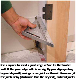
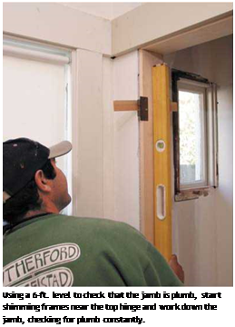
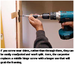
4. Подпись: Use a square to see if a jamb edge is flush to the finished wall. If the jamb edge is flush or slightly proud (projecting beyond drywall), casing corner joints will meet. However, if the jamb is shy (shallower than the drywall), mitered joints will gap. Подпись: Using a 6-ft. level to check that the jamb is plumb, start shimming frames near the top hinge and work down the jamb, checking for plumb constantly. Подпись: If you screw near shims, rather than through them, they can be easily readjusted and won't split. Here, the carpenter replaces a middle hinge screw with a longer one that will grab the framing. Use a Speed Square to determine if the studs on either side of the opening are twisted; if so, you can shim the jambs to make them square. That noted, margin the frame in the opening— that is, center the frame in relation to the wall’s thickness. Ideally, a jamb will be slightly wider, so that it is!4 in. proud (extending beyond) on each side.

5. With the frame margined in the opening, use 2h-in. finish nails or trim-head screws to tack it in place. Place shims behind the top hinge, and nail or screw just below the shims. By not nailing through the shims, you can still adjust them, and if you center tack nails in the middle of the frame, they’ll be covered later by the stop pieces.

Permeability Tests of Unsaturated Soils

As introduced in Chapter 2, the flow of water in saturated soils is commonly de­scribed using Darcy’s law which relates the rate of water flow to the hydraulic gra­dient (Eq. 2.16). Furthermore the coefficient of permeability is relatively constant for a specific soil. Darcy’s law applies also to the flow of water through unsaturated soils. However the permeability of unsaturated soils can not be assumed generally to be constant (Richards, 1931; Fredlund & Rahardjo, 1993; Fredlund 1997). Per­meability now becomes predominantly a function of either the water content or the matric suction (see Chapter 2, Section 2.8). The main reason for this is linked to the fact that the pores in the material are the channels through which the wa­ter flows. In saturated soils all pores are filled with water, allowing the water to move. In unsaturated soils however not all the pores are filled with water. The air-filled pores are therefore not active in transporting water through the material. They can therefore be assumed to behave in a similar way as the solid phase. The permeability of unsaturated soils is therefore lower than in the same soil in a saturated state and decreases as the water content decreases or matric suction increases.

A number of methods exist to measure the unsaturated permeability of soils, both in the laboratory and in the field. As for saturated methods, they can be classified into steady or unsteady methods. In the laboratory the steady state method is rec­ommended as it is relatively simple and has few ambiguities. However the method can be quite time consuming as the flow rate can be very low, especially under conditions of high matric suction. Further it can be difficult to measure the low flow rate accurately due to air diffusion. More recently a faster steady state method has been introduced where a centrifuge is introduced to drive the fluid flow (Nimmo et al., 1987; 1992). The unsteady laboratory methods, such as the thermal method, instantaneous profile method and the multi-step outflow method are usually much quicker than the traditional steady state method but are usually not as accurate. In the field the tension infiltrometer, instantaneous profile method and the cone penetrom­eter methods can be used. Benson & Gribb (1997) give a comprehensive overview of methods to measure the permeability of unsaturated soils.

The coefficient of permeability of unsaturated soils is not routinely measured in the laboratory as the process is cumbersome and quite time consuming (Fredlund 2006). The permeability of unsaturated soils can also be indirectly estimated from the SWCC. This is attractive as the SWCC can be determined in a much shorter time than the permeability’s dependency on matric suction and with greater reliability (Rahardjo & Leong, 1997).

Подпись: Fig. 3.11 Schematic set-up of steady state measurement of the permeability of an unsaturated soil specimen
Permeability Tests of Unsaturated Soils

In the steady state method, the unsaturated permeability is measured under con­ditions of a constant matric suction. A constant hydraulic head gradient is applied over an unsaturated soil sample with a constant matric suction to produce a steady state water flow through the specimen (see Fig. 3.11). A Mariotte bottle can be used to provide a constant pore water pressure to deliver a constant rate of flow. When the rates of water flow entering and leaving the sample are equal, the steady state has been reached and the coefficient of the permeability can be calculated according to Darcy’s law (Eq. 2.15) as

h u і — u2

v = – K – = K— 2 (3.14)

L pwgL

where v is the flow rate of water through the sample, K is the coefficient of perme­ability and h/L is the hydraulic head gradient across the sample (with h the head difference and L the length of the sample). The head difference can be estimated from ui and u2, the readings from the two pore water pressure sensors, converting pressure to head by dividing by the density of water, pw and the acceleration due to gravity, g.

Now the test is repeated for different suctions in order to establish the relationship between the permeability and the suction. A typical measurement of permeability as a function of the matric suction is given in Fig. 3.12. As matric suction is related to water content through the SWCC, and if that relationship is known, the variation of permeability with water content is also known. Notice that, for the suction range illustrated, the coefficient of permeability changes by 6 orders of magnitude.

Matric suction Ф [kPa]

0.1 1.0 10.0 100.0

Permeability Tests of Unsaturated Soils

Fig. 3.12 Permeability as a function of matric suction in an unsaturated soil specimen

PAVEMENT DESIGN AND. REHABILITATION

Aric A. Morse, P. E.

Pavement Design Engineer
Ohio Department of Transportation
Columbus, Ohio

Roger L. Green, P. E.

Pavement Research Engineer
Ohio Department of Transportation
Columbus, Ohio

The movement of people and goods throughout the world is primarily dependent upon a transportation network consisting of roadways. Most, if not all, business economies, personal economies, and public economies are the result of this transportation system. Considering the high initial and annual costs of roadways, and since each roadway serves many users, the only prudent owner of roadways is the public sector. Thus it is the discipline of civil engineering that manages the vast network of roadways.

The surface of these roadways, the pavement, must have sufficient smoothness to allow a reasonable speed of travel, as well as ensure the safety of people and cargo. Additionally, once the pavement is in service, the economies that depend upon it will be financially burdened if the pavement is taken out of service for repair or maintenance. Thus, pavements should be designed to be long lasting with few maintenance needs.

The accomplishment of a successful pavement design depends upon several variables. The practice of pavement design is based on both engineering principles and experience. Pavements were built long before computers, calculators, and even slide rules. Prior to more modern times, pavements were designed by trial-and-error and common sense methods, rather than the more complicated methods being used currently. Even more modern methods require a certain amount of experience and common sense. The most widely used methods today are based on experiments with full-scale, in-service pavements that were built and monitored to failure. Empirical information derived from these road tests is the most common basis for current pavement design methods. More recently, with the ever-expanding power of personal computers, more mathematically based pavement design methods such as finite element analysis and refined elastic layer theory have been introduced. These methods require extensive training to use and are not developed for the inexperienced.

Guerilla Housing

image28We are in the midst of a housing crisis. The Bureau of the Census has determined that more than for­ty percent of this country’s families cannot afford to buy a house in the U. S. Over 1,500 square miles of ru­ral land are lost to compulsory new housing each year. An immense portion of this will be used for noth­ing more than misguided exhibi­tionism. We clearly need to change our codes and financing structure and, most importantly, our current attitudes about house size.

Minimum-size standards are slowly eroding as common sense gradually makes its way back onto the housing scene. Where negotiation and political pressure have failed to eradicate antiquated codes, lawsuits have generally succeeded. But these measures all take more time, money and patience than many of us can muster. To make things worse, local covenants prohib­iting small homes are being enacted more quickly than the old prohibitions can be dismantled. These restrictions are adopted by entire neighborhoods of people needlessly fearful for their property values and lifestyle.

The process of changing codes and minds is slow, and the situation is dire. As long as law ignores justice and reason, just and reasonable people will ignore the law. Thousands of Americans live outside the law by inhabiting

houses too small to be legal. Some of them cannot afford a larger home, while others simply refuse to pay for and maintain unused, toxic space. These people are invariably good neighbors: they live quietly, in fear of someone’s reporting them to the local building inspector.

image29

Williamsburg, VA (facing page) and Klamath, CA (above)

Comparison of Results of Example II Using German Proportions of SMA Composition

In Chapter 2, Table 2.1 cites the recommended ratios of individual SMA coarse aggregate fractions from the German DAV handbook (Druschner and Schafer, 2000). The comparison of the achieved result from Example II with ratios required in Germany is shown in Table 6.10.

The comparison in Table 6.10 shows that our SMA differs both from the origi­nal Zichner proportions and the contemporary ones recommended in Germany. The original German SMA does not contain such a great amount of the coarsest grains. Therefore let us design the same mix according to the German DAV proportions. The result is shown in Figure 6.8. The gradation curves of DAV and Zichner have a gentler shape, making laydown and compaction easier. Not using the maximum quantities of the coarsest grains makes the mix less open graded. Such an SMA mixture will probably be less permeable to water.

A Practical Look at Deep-Energy Retrofits

Подпись: ENERGY EFFICIENCY■ BY MARTIN HOLLADAY

I

f you pay any attention to building sci­ence, you have probably seen the term "deep-energy retrofit"—a phrase being thrown around with the colloquiality of "sustainability" and "green." Like the word "green," the term "deep-energy retrofit" is poorly defined and somewhat ambiguous. In most cases, though, "deep-energy retro­fit" is used to describe remodeling projects designed to reduce a house’s energy use by 50% to 90%.

Remodelers have been performing deep – energy retrofits—originally called "superin­sulation retrofits"—since the 1980s. Most deep-energy retrofit projects are predomi­nantly focused on reducing heating and cooling loads, not on the upgrade of appli­ances, lighting, or finish materials.

While a deep-energy retrofit yields a home that is more comfortable and healthy to live in, the cost of such renovation work can be astronomical, making this type of retrofit work impossible for many people. Those of us who can’t afford a deep-energy retrofit can still study the deep-energy ap­proach, using it to shed light on more prac­
tical and cost-effective measures to make any home tighter and more efficient.

How Deep?

No standard-setting agency has established a legal definition of a deep-energy retrofit, but the term generally refers to retrofit measures that reduce a home’s energy use by 50% to 90% below that of a code-minimum house— or, according to a more lenient definition, below preretrofit levels. Probably fewer than 100 homes in North America have completed deep-energy retrofits that conform to the strictest definition of the term.

A house that has undergone a deep – energy retrofit typically ends up with R-20 basement walls, R-40 above-grade walls, R-60 roofs, and U-0.20 windows. A typical air­tightness goal, determined by a blower-door test, is 1.2 ACH (air changes per hour) at 50 pascals.

A deep-energy retrofit doesn’t make sense in all climates, and not every home is a good candidate for the work. Cold-climate homes often have higher energy bills than homes in more moderate climates, so a cold-climate

A Practical Look at Deep-Energy Retrofits
An old house with a new shell. This deep-energy retrofit in Somerville, Mass., received 4 in. of spray polyurethane foam on its exterior. (For more information, see the case study on p. 45.) However, not all energy upgrades have to be so elaborate.

Подпись: 1 Phases 1. Get an energy audit. An auditor will evaluate your home and develop a list of energy-retrofit measures (see “Every House Needs an Energy Audit,” pp. 4-11). 2. Perform air-sealing work, using blower-door test results to direct you. 3. Install a mechanical ventilation system once you've tightened up the building envelope. 4. Start insulating the home from the top, because a lot of heat is lost through ceilings and roofs. 5. Insulate the interior side of basement walls, a relatively easy task because basement walls are accessible. 6. Install dense-pack cellulose insulation into any empty stud bays of above-grade walls. This work is affordable and cost-effective. 7. Install thick rigid foam on the exterior of the sheathing and new high-performance replacement windows. 8. Finally, install a new heating system. This should be done last, because the unit should be sized for your new high-performance home. If a new heating unit is installed earlier in the project, it's likely to be too big.

home may be a better candidate than a home in a moderate climate or a home that already has low energy bills. A house with a simple rectangular shape and a simple gable roof is easier and less expensive to retrofit than a house with complicated exterior ele­vations, bay windows, dormers, or a roof full of hips and valleys. Most of the deep-energy retrofits include the installation of a new layer of exterior insulation. Intricate archi­tectural details add to the difficulty of such retrofit work, driving up costs. Homes with simple exterior trim and uncomplicated cor­nice details are much easier to work on than Victorian homes with gingerbread trim. Be­cause many deep-energy retrofits require ex­isting roofing and siding to be replaced, the best candidates for deep-energy retrofit work are houses that are in need of new roofing and siding.