Installing French Doors

Installing double doors requires more plumb and level readings, shim adjustments, and—above all—more patience than hanging a single door, but the procedure is much the same. So we’ll zip through the steps covered earlier to get to the heart of the matter. figuring out why the doors don’t meet perfectly in the middle and what to do about it.

INSTALLATION: A QUICK RECAP

► Measure the RO to make sure it’s big enough to install the door frame.

► Using a 6-ft. spirit level, see if the floor is level and the sides of the RO are plumb. Also check the walls on both sides of the RO for plumb. If the bottom of the opening is more than !/i in. out of level, correct the situation. French doors are wide and heavy and need to rest solidly on a level opening. Otherwise, they can rack and bind.

image210

Install cap flashing atop the head casing, nailing its upper flange as high as possible. Here, this flashing will be overlapped by flashing paper and stucco. Cap flashing should overhang the casing slightly along the front and at the ends of the casing, so water drips free.

► The sides of the RO can be shimmed, but if the wall framing isn’t plumb, place a 2×4 block against the base of the wall and strike the block with a sledgehammer. Go easy: Numerous gentle hits will cause less damage than one mighty blow.

► Remove the doors from the frame, center the frame in the RO, and tack it up with one 10d finish nail at the top of the frame on each side.

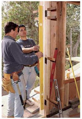
► Plumb and shim one side of the frame first. Shim behind the top hinge first, then the bottom, then the middle hinge—rechecking that the jamb is plumb, square, and flush to the wall as you go. Nail (or screw) the frame at each shim point. Shim and tack the other side jamb; shim and tack the head jamb, placing shims at thirds of the RO width.

► Next, rehang the doors. If everything is perfect, the doors will be in the same plane. There will also be a uniform Иб-in. to ki-in. clearance around the doors and an even ih-in. gap where they meet at the center. More likely, you’ll need to re-adjust shims. When the fit is perfect, use a utility knife to score the shims before snapping them flush to the finish walls.

image211Подпись: When installing casing, set it back 1/4 in. from the jamb edges. This setback, called a reveal, tricks the eye: Even if jambs or casings are not straight, their joints look straight. Door-Casing Reveal

Installing French Doors

FRENCH DOOR

image212

Подпись: Tilt French doors into place. Tack the cleats to the upper corners of the frame to keep the unit from falling through the opening and to ensure that the jambs will be flush with the sheathing.

Because French doors are wide and heavy, it’s crucial that the subfloor of the opening be level. Insufficiently supported, French-door thresholds can flex, misalign, and admit water.

Barely above grade, this opening needed thorough waterproofing. Self-adhering bituminous water­proofing membrane seals the sheathing/foundation joint (just visible, lower left); this membrane is further covered by galvanized sheet metal. The rough­opening bottom is being wrapped with foil-faced peel-and-stick flashing, which extends up 4 in. onto the studs at each end.

TIP

Prime and paint all six sides of exterior doors—especially the top and bottom edges—before putting on the hardware and weatherstripping. Protect unfinished wood with at least one coat of primer and two coats of good-quality oil-based paint. Also carefully prime lock holes, leaf gains, and all edges. Finally, caulk panels after priming and before painting so there’s no place for water to penetrate.

image213image214llll

When jambs are bowed, a plumb bob gives more accurate readings than a spirit level. Hang the bob from a nail near the top of the frame. When the jamb is plumb, readings to the string will be equal along its length.

When there’s too much of a gap where French doors meet in the middle, use a flat bar to ease the jambs toward the middle so you can slip shims behind them. Tweak and reshim the doors till they seat correctly and close evenly in the center.

Подпись: Door leafimage215

I Bending a Hinge Knuckle

Step 2-Spread Makeup

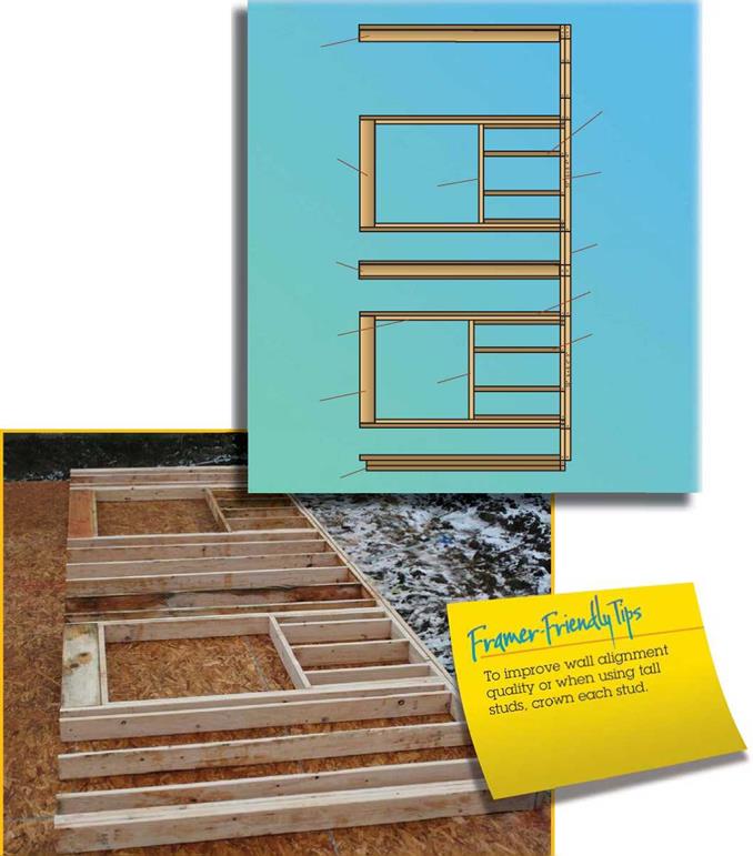
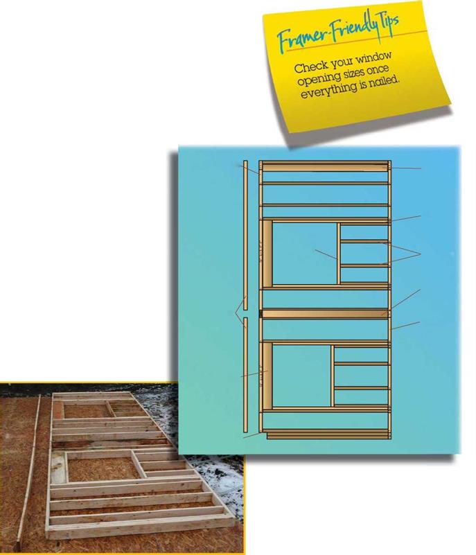
Usually, one member of the framing crew does all the cutting. This promotes an efficient workflow and ensures consistent cuts. The person doing all the cutting must work fast enough to stay ahead of the remaining members of the crew.


Comer


Cripple


Header


Bottom plate


Sill


Top plate


Backer


Stud


Trimmer


Cripple


Step 2-Spread Makeup

Step 2-Spread Makeup

Подпись: Sill

Header

Beam

pocket

Spread makeup: stud/trimmers, backers, corners, cripples, sills, beam pockets.

Step 2-Spread Makeup3: Spread studs 4: Nail headers to studs

5: Nail top plate to studs & headers

Подпись: Following the nailing patterns discussed in Chapter 2, the wall frame components can now be assembled. Pneumatic nailers reduce the amount of time required to perform this task. Step 2-Spread Makeup Подпись: Sill Step 2-Spread Makeup

6: Nail bottom plate to studs 7: Nail double plate to studs

Header

Beam pocket

Spread remaining wall parts and nail.

Shear and Shear Failure

Shear failure is much more difficult to envision than bending failure. In fact, with light frame construction, shear failure seldom comes into play, whereas it is an important consideration for heavy timber framing, particularly with a very heavy load such as an earth roof or a steam train.

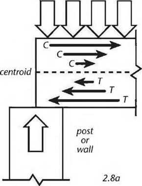
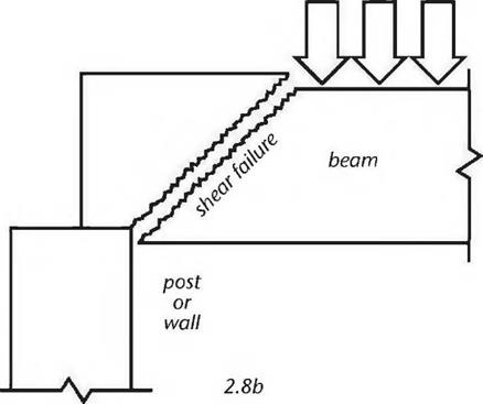
Подпись: Fig. 2.8 a Left: White arrows indicate a heavy load on a beam supported by a post or wall. Horizontal arrows indicate compression (C) and tension (T) forces. The top of the beam is in compression and the bottom surface is in tension. The dotted line indicates the centroid or neutral axis. Fig. 2.8b Right: Shear failure occurs when adjacent layers of wood separate because of "sliding" forces (called "shear parallel to the grain”) taking place in the wood, which make the beam much less resistant to heavy loads. This sliding is caused by differentials in compression and tension forces between one layer of wood and the next. This type of failure occurs near the beam's support.One good way of explaining shear is to think of it as a combination of compression and tension stresses. Remember that the top surface of a beam is in compression, the bottom surface is in tension, and the centroid (middle part of the beam) is neutral (thus also called the neutral axis.) Fig. 2.8a shows the compression and tension forces at one end of a beam, where it is supported over a post or wall. The arrows show the compression and tension forces. Note that the arrows are pointing in opposite directions, and that the strength of the compression or tension forces diminishes closer to the neutral axis. Fig. 2.8b shows the kind of failure that can happen when the stresses in the beam cause the wood fibers to slide along each other at varying rates. Not surprisingly, the separations often follow annual growth rings. This is why woods prone to shake, such as hemlock, are also low in shear strength. (Shake is the term for a weakness in wood caused by separations between annual growth rings.) It is no coincidence that if a two-by-six hemlock plank is tossed too casually to the ground, it will shatter parallel to the grain.

heavy load

image18


image19

image20

Shear and Shear Failure

Fig. 2.9: The arrows indicate lines of thrust from the roof.


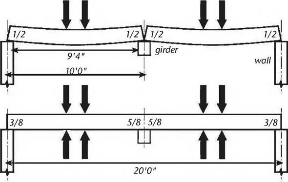
Fig. 2.10: Deflection is reduced with a double span as shown in the lower diagram, and bending strength is increased… but shear strength is decreases by about 25

percent.


image21

girder at the center of the building. If the rafters are bearing four inches onto the walls and girder, the clear span is actually 9 feet 4 inches (2.84 meters). In the bottom picture, we will use a 20-foot (6 meter) long rafter to do the same job.

The reader will probably not be surprised to learn that the situation at the top will promote more deflection in the rafters (deflection is discussed below) and will decrease the bending strength a little bit. The one-piece construction shown in the lower diagram “stiffens” the structure: greater bending strength and less deflection.

However — and this is the strange and interesting part — the structure at the top is actually stronger on shear. The structure in the lower part of the diagram has some very high shear stresses occurring on the top surface of the rafter where it passes over the girder. The effect of the sliding feature of the wood fibers over the neutral axis is increased, because the compression stresses on the top surfaces of the two spans are causing a tremendous tensile stress at the top of the rafter directly above the girder. Think of it: If the two spans are each trying to pull away from each other, because of the load on each span, those wood fibers at the top of the rafter (over the center) are working really hard not to break on tension. All of this translates to lower shear strength at this location. In the top picture, shear stresses over the supports are clearly the same at all four shear locations, expressed by the fractions V2 in each case. But, in the bottom picture, the shear stresses are expressed as 5Л at the walls at the right and left but increase to Vs where the long rafter is supported by the girder in the middle.

The upshot is that shear strength is gained by using two ten-footers instead of a single 20-footer supported in the middle. It is also true, as we have said, that bending strength is slightly diminished in the former example, and deflection is increased — but if the weak point in the engineering happens to be in shear, the former example may be better. This situation may work in our favor, when you consider that two ten-footers are much easier to handle — and certainly less expensive — than a single twenty-footer.

Leveling a Doorsill

There are several ways to level an exterior doorsill. After you’ve installed a floor pan, place a spirit level across the bottom of the rough opening (RO) and insert pressure – treated wood shims under the tool till it reads level. Tack shims to plywood subfloor­ing to keep them from drifting, and then install the prehung door unit. If the subfloor is concrete, use construction adhesive to spot-tack the shims. Or you can place the door frame into an unlevel opening, use a flat bar to raise the low end of the frame sill, and insert shims under the sill till it’s level. To prevent flexing between shims, space shims every 12 in. beneath aluminum/combination or oak sills, or every 6 in. beneath sliding-door sills.

The problem with any of these solutions is that many sills—especially hollow alu­minum ones—are so thin that they may flex between shim points. If there’s 1/4 in. to V2 in. of space under the sill, use a Vf-in. tuck-pointing trowel (see the photo on p. 198) to push dry-pack mortar into the spaces between the shims, compacting the mortar as best you can. Or fill under the shimmed-up sill with nonshrinking mortar, such as an epoxy mortar/grout.

The only way to correct an out-of-level opening without shims is to rebuild it, which is rarely simple. For example, you can remove the subfloor and power-plane down the tops of joists till they are level and then install pressure-treated plywood atop them, but if nearby floors are out of level, you may need to level them next. Jacking is another option.

Подпись:Подпись:image203Подпись: PROTIP Caulk around the rough opening, rather than the door frame or casing; if you instead caulk the frame, you're likely to get sticky fingers lifting it into place. If it's necessary to remove a frame after pressing it into caulking, reapply a continuous bead of caulking around the opening. llll

EYEBALLING THE FRAME

Once you’ve prepped the opening, place the door unit in it to see what needs tweaking. This is a dry run, so frame jambs needn’t be perfectly plumb or level—just close.

1. Test-fit the door frame in the opening. Center it right to left in the RO; then margin the frame. There should be!4 in. to h in. of clearance around the frame so it can be shimmed to the RO. Jamb edges should Vu in. proud of the interior wall surfaces to accommodate framing quirks.

2. Is the door frame square? If the frame is square, there should be an even space between the door and the frame jambs; if not, the frame is skewed. To resquare it, remove the frame from the opening, and— with the door still hung—tilt the frame to one side until acute corners (less than 90°) become square and the door fits evenly.

3. Remove the unit, make necessary final adjustments to the RO, and then caulk the bot­tom of the opening. If the door unit is precased, apply a bead of caulking to the exterior wall around the RO, inward about h in. from the edges of the opening. If the prehung door unit is uncased, don’t caulk around the opening yet, just caulk the bottom of the RO.

INSTALLING AN EXTERIOR FRAME

As with interior doors, there is no one right way to install a prehung exterior door. Some carpen­ters prefer to install door frames with doors hung. Others prefer to remove the door, plumb and attach the hinge jamb, rehang the door, then attach the other jambs. Though the accompany­
ing photos show the second method, both meth­ods are described here.

Method 1: The door stays hung. Pry off the

shipping blocks, remove the plastic plugs from the lock bore, and place the unit into the RO. (At this point, assume the doorsill is level.) Center the unit left to right in the opening; press the cas­ing into the caulking; and then, while a helper keeps the unit from tipping, drive a 10d galva­nized finish nail (or 3-in. screw) into each side jamb about 6 in. above the sill, or into nailing fins (flanges). Leave the nail heads sticking up so you can pull them if needed.

Hold a 6-ft. level against the inside of the hinge jamb to see if it’s plumb. If not, insert a flat bar between the frame and the RO near the top of the frame, and pry the frame out on one side till the jamb is plumb. Then drive a nail into the top of each jamb, about 6 in. below the top of the frame. Finally, eyeball the inside of the door frame to make sure there’s a uniform clearance (usually Иб in. to /8 in.) between the door and the frame. Use nails to draw the frame to the RO or adjust the shims until the clearance is uniform.

Speaking of shimming, precased units can be shimmed only from the inside. Unbacked by shims, frames can twist as the door swings. To shim from the inside, insert a shim, fat end first, till it butts

image204

Shim and secure the hinge jamb first, checking for plumb often. Here, installers place shims slightly above and below the hinges so the hinge screws sticking through the jamb won’t snag on the shims. Screwing the jambs to the framing facilitates adjustments.

against the back of the casing; then slide addi­tional shims, thin edge first, till shims are tight. Nail or screw below each stack of shims; then close the door and see if it seats evenly against the frame. Once you’ve corrected that, secure the frame to the rough opening, and finish the exterior.

Method 2: Remove the door. After leveling and prepping the opening, pull the hinges and remove the door from the frame. Screw temporary cleats to the outside of the frame—or to the exterior sheathing itself—so that when the frame is placed into the RO, the outer edges of its jambs will be flush to the sheathing.

Center the frame left to right in the opening, and check the jambs for plumb and the sill for level. If it’s necessary to shim the doorsill to level, place the first shim under the jamb on the low side. Plumb and attach the hinge jamb first, inserting the first set of shims behind the top hinge. Remove the middle hinge screw(s) so you can slide the shims freely as you adjust them. Then drive a 10d galvanized finish nail or a 212-in. screw just below the shims, in the center of the hinge jamb; this holds the shims snugly, but you can still adjust them. Shim behind the bottom hinge, check for plumb, and then shim behind the middle hinge. Adjust the shims as needed to attain plumb; then shim behind the corners of the hinge jamb, top and bottom.

With the hinge jamb securely attached, rehang the door. (Get help; exterior doors are heavy.) Close the door and note how it fits the frame. Without weatherstripping, there should be an even gap, /и in. to ‘/ in. wide, around the door, and the corners of the frame should be square. If the door hits the edge of the latch jamb, that jamb may be bowing into the RO or the shims behind the hinge jamb may be too high.

Adjusting an uncased exterior door frame is very similar to “working” an interior door frame.

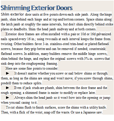
Подпись: After plumbing and securing the hinge jamb, rehang the door so you can use it as a gauge to align the latch jamb correctly. This method is particularly helpful if the door is slightly twisted or warped, because you can align the latch jamb to the door.Подпись: As you adjust latch and head jambs, make sure there's an even gap (typically ’/ in.) between the door and the jambs all around.image205Подпись: Shimming Exterior Doors Shim exterior door units at five points down each side jamb. Along the hinge jamb, shim behind each hinge and at top and bottom corners. Space shims along the latch jamb at roughly the same intervals, but don't shim directly behind strike plates or deadbolts. Shim the head jamb midway and at both corners. Exterior door frames are often installed with a pair or 10d or 16d galvanized nails spaced every 16 in.; using two nails at each interval keeps the frame from twisting. Other builders favor 3-in. stainless-steel trim-head or plated flathead screws, because they grip better and can be removed if needed; countersink flathead screws. In addition, many builders remove the middle hinge screws, shim behind the hinge, and replace the original screws with 3%-in. screws that sink deep into the roughopening framing. Here are some fine points to consider: ► It doesn't matter whether you screw or nail below shims or through them, as long as the shims are snug and won't move; if you screw through shims, predrill them to reduce splits. ► Even if jack studs are plumb, shim between the door frame and the rough opening; a shimmed frame is easier to modify or replace later. ► Always shim the head jamb so it won't bow into the opening or jump when you nail casing to it. To cut shims flush to finish surfaces, score the shims with a utility knife. Then, with a flick of the wrist, snap off the waste. Or use a Japanese saw. Shim the latch jamb and then the head jamb. When all is okay, secure the frame with two
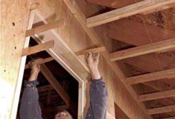
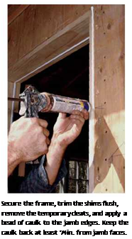
image206

Shim the head jamb after plumbing the latch jamb. If the frame is uncased, you can insert shims from both sides and easily slide them in and out. The white line inside the jambs is kerf-in weatherstripping.

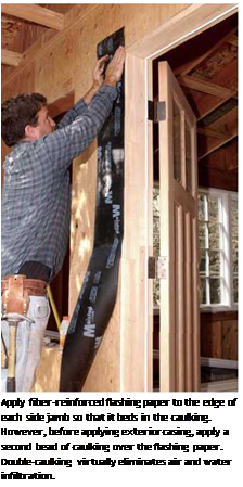
Подпись:Подпись: Apply fiber-reinforced flashing paper to the edge of each side jamb so that it beds in the caulking. However, before applying exterior casing, apply a second bead of caulking over the flashing paper. Double-caulking virtually eliminates air and water infiltration. 16d galvanized finish nails spaced every 16 in. and in 1 in. from the edge. Then seal the frame to keep out weather, apply casing, and flash it, as described in the next section.
FINISHING THE EXTERIOR

If you installed an uncased unit, now seal the outer jamb edges and install the casing.

1. If the unit’s sill has horns that extend beyond the side jambs, cut down each horn so that it is as long as exterior casing is wide plus /a in. for a reveal (the amount that the casing is set back from the inner edge of the frame jamb). Casing legs sit on horns, so cut casing bottoms at the same angle as the sill. (Use an adjustable bevel gauge to record the angle.)

2. Before attaching casing, however, run a single bead of siliconized acrylic caulking along the side and head jamb edges. Keep the caulking back at least J4 in. from the inner edge of the jambs so it’s not visible in the %-in. reveal.

3. Next, cut two fiberglass-reinforced flash­ing strips a in. to 6 in. longer than the length of the side jambs. Press a strip against the caulked jamb edge, again holding back the strip at least

h in. from the inner edge of the jambs. Staple the portion of the flashing strip that overlaps the sheathing so the strip doesn’t blow off.

4. Attach casing to both sides of the jam. Create a reveal by setting back the inner edges of casing І4 in. from the jamb edges. Then nail up the head casing. If the corners are mitered, nail through the joint to draw the jambs together, as shown in the left photo below. Note. There’s no flashing strip under the head casing; it’s applied over the cap flashing to direct water away from the sheathing.

image209

As you install casing, drive a finish nail through corner miter joints to keep them from separating. You can also glue the joint, but here, stucco will help keep the joint from moving. Note the ’/4-in. reveal between the casing and the edge of the jamb.

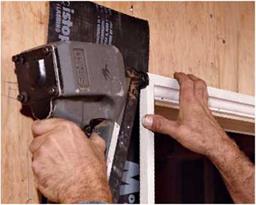
5. Once the head casing is up, attach the cap flashing (head flashing), which is often prefabbed from vinyl or metal. It’s easy enough to make your own from 26-gauge aluminum or galvanized steel; use aviation snips to cut and fold it and a rubber mallet to shape it. Caulk the head casing/ sheathing joint, and then press the cap flashing down onto the casing. Use big-head roofing nails to nail the top flange of the flashing. Then staple strip flashing over the top flange of the flashing, and run housewrap and/or siding over that.

At this point, you’re ready to install hardware, insulate between the jambs and the RO (use a mild-expanding spray foam), and attach the inte­rior casing.

Sadd el Kafara11: the first known large dam… and the story of its failure

In the IIIrd or IVth dynasty, about 2700 or 2600 BC, The Egyptians undertook the con­struction of a dam on an ephemeral tributary of the Nile, the wadi Garawi, some ten kilo­meters southeast of Memphis. This effort, coinciding with the period of construction of the great pyramids of Giza, is part of the development and improvement of the region around the capital. The remains of the dam are still visible today on both banks of the wadi, and were studied in 1982 by a Germano-Egyptian team.[97]

The dam comprises two rock faces with central core of random material. The upstream and downstream faces are protected by cut blocks forming steps of about 30 cm in height (Figure 3.3). It is the length (113 m) and especially the height (14 m) of this structure that earn its recognition as the oldest known large dam. Even more sur­prising is the dam’s colossal thickness, nearly 100 m wide at the base and 66 m at the crest. This excessive thickness shows that dam techniques were still somewhat primi­tive in Egypt of the IIIrd millennium BC.

Sadd el Kafara11: the first known large dam... and the story of its failure

Figure 3.3 Remains of the Sadd el Kafara dam (about 2600 BC), on the right bank of the wadi Garawi. The oldest known large dam. View from upstream (photo of G. Garbrecht)

Sadd el Kafara11: the first known large dam... and the story of its failure

Figure 3.3a Cross section of the structure of the Sadd el Kafara dam on the wadi Garawi. The outside blocks form about 30 stairsteps. After Garbrecht (1985).

The most likely purpose of this dam was to protect downstream cultivated and inhabited areas riparian to the Nile from the violent floods of the wadi Garawi. Indeed, the structure’s permeable core argues against the hypothesis of a reservoir to store water for agricultural use. In any case, irrigation in Egypt at this period remains entirely based on floods of the Nile. Curiously, examination of the reservoir area shows no trace what­soever of sedimentation, suggesting that it was not the destiny of this important dam to survive very long.

We have already mentioned that the wadi Garawi is normally dry but can have vio­lent floods. Its bed slope is fairly steep at about 10 m per kilometer, and the flood dis­charge can be estimated at between 50 and 250 m3/sec. The storage capacity of the reservoir (620,000 m3) is insufficient to capture all the water of a large flood. On the left bank, there is a terrace whose elevation is 1.5 m below that of the dam crest. This terrace therefore can serve as a natural spillway, whether or not this was intended by the dam’s designers. The spillway has a capacity of the order of 85 m3/sec, beyond which flow the dam can be overtopped. Given its broad dimensions and rock protection, the dam should have been able to resist partial overtopping. These analyses led Gunther Garbecht to hypothesize that the dam failed before it was completely finished, when the upstream rock face had been built to its nominal height but neither the downstream face nor the filling of the core were completely finished. Submerged by an exceptional flood, the dam could have been ruined by erosion of the central core and collapse of the upstream face. This failure would surely have resulted in downstream destruction, and the memory of this catastrophe could explain the absence of new dam construction in Egypt for many centuries to come.

Zichner’s and DAV’s SMA versus 30-20-10 Rule

The 30-20-10 rule has more or less rigid proportions of gradation (expressed by

amounts passing through selected sieves). Zichner proposed the amount of coarse

a

Подпись:Подпись:Подпись: 10 20 30 40 50 60 70 80 90 100 Подпись:Подпись:image51a

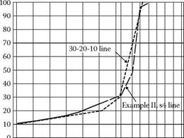
FIGURE 6.9 An SMA mix of Example II, Stage 4, compared with the line of the 30-20-10 rule.

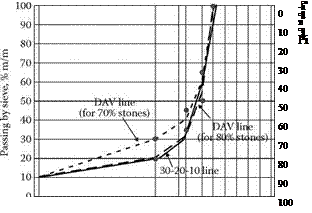
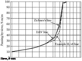
aggregates over a very wide range (65-80%), with a recommendation for 70-75%. His MASTIPHALT (SMA 0/12.5, mm) with 75% of grains larger than 2 mm has a gentle gap gradation with also more or less fixed proportions. There is no doubt that the 30-20-10 rule creates quite different mixtures than those created according to Zichner’s ideas. The other issue is with DAV’s proportions (Table 6.10) because these express the proportions between aggregates inside the coarse fraction. Hence the proportions mentioned can be applied to the amount of coarse aggregates fraction within the permitted range (e. g., 70-80%). In Figure 6.8 we compared the DAV line applied with a fixed 75% of coarse aggregates as we designed in Example II. Now we can evaluate the DAV proportions applied to a new content: 80% of coarse aggregates (similar to the 30-20-10 rule). After calculation of the gradation larger than the 2.0 mm sieve, according to DAV rules we can see grading curves as shown in Figure 6.10. The final assessment of the 30-20-10 rule line is slightly below the extreme line permitted by DAV propor­tions at 80% of coarse aggregate fraction. As is the case in Germany, there is a trend to decrease the amount of coarse aggregate content to 73-76% (Druschner, 2005). Taking into account this assumption, the 30-20-10 rule line is too low.

One can see in Figure 6.10 that the latest German regulations TL Asphalt-StB 07 for SMA 11S requires 35-45% of material passing a 5.6 mm sieve. It shows that Zichner’s or DAV’s proportions (for 70-76% of stones) are still in use.

6.3.2.2.2 Summary of Example II

The following is a list of the conclusions drawn from analyzing Example II: [24]

image52

FIGURE 6.10 Comparison of SMA gradations: 30-20-10 rule (solid line) and DAV lines for 70% and 80% of coarse fraction (dotted lines). The points show gradation limits in coarse fraction established in the newest German TL Asphalt-StB 07 for SMA 11S.

• The ratios of the coarse aggregate fractions cannot be even because this causes a loss of the necessary discontinuity of gradation.

• Quantities of the finest grains in the coarse fraction should be reduced when composing the total coarse aggregate fraction.

• The content of grains larger than 2 mm (the coarse aggregate) in an SMA aggregate mix do not explicitly determine its aggregate skeleton and prop­erties; aggregates passing the 5 or 8 mm sieves are also needed.

• Increasing the quantity of particles larger than 5 mm leads to opening the mix; this effect is even more noticeable when raising the content of particles larger than 8 mm.

Replacing an Exterior Door

To replace an exterior door, first remove the interior and exterior casing to expose the door frame and the rough opening. Proceed carefully, minimizing damage to the siding and finish surfaces whenever possible. Exposing the rough opening enables you to measure it exactly and inspect for water damage or rot, which must be repaired before installing a new unit.

To remove casing without breaking it, use a flat bar to raise it slightly; then use a reciprocating saw with a metal-cutting blade to cut through the casing nails.

(Wear safety glasses.) Cutting nails is far easier on surrounding surfaces than prying alone. However, some casing can’t be removed without destroying it—stucco molding, for example.

In many older houses, the sill will be a 2-in.-thick board notched into the framing so that it sits flush with the subfloor. If it is in decent shape, leave it. If it has rot, cut out the sill and install a floor pan over the framing before installing a replacement sill that’s flush to the subfloor. If there’s a sloping threshold atop the sill, remove it.

It will probably be weathered, and anyway, the new preframed door must sit on a level surface. (New exterior doors typically have a combo sill-threshold preattached to the side jambs.)

To install the new door unit, remove the existing door frame, preferably by cutting through the nails holding it to the rough opening so that you can pull out the frame in one piece. That way, should the new frame not fit, you can easily replace the old frame and rehang the door so you won’t be without a door while you correct the problem.

Tensiometers

One of the most common devices for measuring suction is a tensiometer. A ten­siometer consists of a fine porous ceramic cup connected by a tube to a vacuum

Technique/Sensor

Suction

component

measured

Measurement range (kPa)

Equilibrium time

Laboratory/Field

Tensiometers

Matric

0-100

Several

minutes

Laboratory and field

Axis translation techniques

Matric

0-1500

Several

hours-days

Laboratory

Electrical/

thermal

conductivity

sensors

Matric

0-1500

Several

hours-days

Laboratory and field

Contact filter paper method

Matric

0-10000

2-5 days

Laboratory and field

Non contact filter paper method

Total

1000-10000

2-14 days

Laboratory and field

Table 3.2 Summary of common laboratory and field techniques for measuring soil suction. Based on Lu & Likos (2004) and Rahardjo & Leong (2006)

gauge (see Fig. 3.13). The entire device is filled with de-aired water. The porous tip is placed in intimate contact with the soil and the water flows through the porous cup (in or out) until the pressure inside the ceramic cup is in equilibrium with the pore water in the soil. The reading on the pressure measuring device, once corrected for the water column in the device, is the matric suction (Apul et al., 2002). The water pressure that can be measured by this method is limited to approximately -90 kPa, otherwise water will begin to boil inside the tensiometer (“cavitation”). Tensiome­ters have been found to provide the best measuring technique for low-range suction as they measure the pore pressures directly and respond promptly to pore water pressure changes (Rahardjo & Leong, 2006).

Подпись: Fig. 3.13 Example of Tensiometer, consisting of ceramic cup and plug connected to tubes (Krarup, 1992). Reproduced with permission of the Road Directorate / Danish Road Institute
Tensiometers

Lately, “high-capacity” tensiometers have been developed (e. g. Ridley & Burland, 1993; Guan& Fredlund, 1997; Tarantino andMongiovi, 2001). Whencou – pled with specialised operating procedures, for example, cyclic prepressurization techniques, they have been shown to be applicable for matric suction up to 1500 kPa. Comparisons with established measurement systems have shown high-capacity ten­siometers to be relatively reliable and quite rapid in terms of response time.

Comparison of Results of Example II with the 30-20-10 rule of SMA Composition

According to the rule described in Section 6.2.2, proper stone-to-stone contact is created if the percentage of aggregate passing the 0.075 mm, 2.36 mm, and

4.75 mm sieves equals 10%, 20%, and 30%, respectively. Table 6.11 shows the comparison between the achieved result of Stage 4 and ratios according to the 30-20-10 rule.

There are some noticeable differences. First, the 30-20-10 SMA should contain more aggregates larger than 2.36 mm (80%), whereas the relevant SMA of Example I was designed at only 75% on the 2.0 mm sieve. With regard to particles larger than

Recommended Ratios of SMA 0/11S according to German DAV Handbook Compared with the result of sMA design in example ii

TABLE 6.10

sMA coarse

original

zichner’s

recommended ratios within SMA coarse Aggregates’ Fraction According to the german guidelines for

SMA of

ratios of the Mix converted According to the german DAv guidelines (for 75%

Fraction

proportions of

SMA 0/11S (Mass

example

of grains retained

components

mastiphalp

Fractions)b

II, Stage 4

on Sieve 2.0 mm)

Fraction 2/5.6

10%

1 part

5%

10.7%

Fraction 5.6/8

27%

2 parts

15%

21.4%

Fraction 8/11.2

38%

4 parts

55%

42.9%

Total

75%

7 parts

75%

75.0%

a See Table 6.4.

b From Druschner, L., Schafer, V., Splittmastixasphalt. DAV Leitfaden. Deutscher Asphaltverband, 2000.

0

Подпись:10

Подпись: a a CD _<D '£> c о 43 CD c "ns CD Cl 20

30

40

50

60

70

80

90

100

FIGURE 6.8 SMA mix of Example II, Stage 4, adjusted to the ratios recommended by the German DAV handbook compared with its original gradation and Zichner’s proportions.

TABLE 6.11

Подпись: recommended approximate SMA Ratios According to 30-20-10 Rule (for SMA 0/12.5) 10% (m/m) 20% (m/m) 30% (m/m) Подпись: SMA 0/11 of the Example II, Stage 4, the Approximate Conversion of Passing to U.S. Sieves 10% (m/m) On the 2.0-mm sieve 19% (m/m) On the 5.6-mm sieve 31% (m/m)
Подпись: gradation Passing by the 0.075-mm sieve Passing by the 2.36-mm sieve Passing by the 4.75-mm sieve

Recommended SMA Ratios according to the 30-20-10 rule Compared with the result of sMA Designed in example ii

4.75 mm, the result obtained in Example II is consistent with the requirement con­cerning 30%. Figure 6.9 shows the SMA corrected in such a way that its ratios are in conformity with the assumptions of the 30-20-10 rule.

The SMA designed according to the 30-20-10 rule is more gap graded than our SMA in Example II, which is especially evident in the percent passing the 2.0-mm sieve. In general, mixtures with such a strong gap in grading are harder to compact and are more permeable. On the other hand, one can get very strong skeleton with such a clear gap grading (stone-to-stone contact).

Gamma distribution and variations

The gamma distribution is a versatile continuous distribution associated with a positive-valued random variable. The two-parameter gamma distribution has
a PDF defined as

f g(x | а, в) = 1 (x/в)а—1 ex/fl for x > 0 (2.72)

вГ(а)

in which в > 0 and а > 0 are the parameters and Г(») is a gamma function defined as

ta-1e-t dt


Г(а)


(2.73)


0


The mean, variance, and skewness coefficient of a gamma random variable having a PDF as Eq. (2.72) are

gx = A.1 = ав = ав2 Yx = 2/ja (2.74)

In terms of L-moments, the second-order L-moment is

Подпись: (2.75)вГ(а + 0.5)

^2 = ,—r( s

Gamma distribution and variations

(а)

where f is the lower bound. The two-parameter gamma distribution can be reduced to a simpler form by letting Y = X/в, and the resulting one-parameter gamma PDF (called the standard gamma distribution) is

Подпись: (2.78)f g(y | а) = –Цya V for y > 0 Г(а)

Tables of the cumulative probability of the standard gamma distribution can be found in Dudewicz (1976). Shapes of some gamma distributions are shown in Fig. 2.20 to illustrate its versatility. If а is a positive integer in Eq. (2.78), the distribution is called an Erlang distribution.

When а = 1, the two-parameter gamma distribution reduces to an exponential distribution with the PDF

f EXp(x | в) = e х/в/в for x > 0 (2.79)

An exponential random variable with a PDF as Eq. (2.79) has the mean and standard deviation equal to в (see Example 2.8). Therefore, the coefficient of

Подпись: Figure 2.20 Shapes of gamma probability density functions.

variation of an exponential random variable is equal to unity. The exponential distribution is used commonly for describing the life span of various electronic and mechanical components. It plays an important role in reliability mathe­matics using time-to-failure analysis (see Chap. 5).

Two variations of the gamma distribution are used frequently in hydrologic frequency analysis, namely, the Pearson and log-Pearson type 3 distributions. In particular, the log-Pearson type 3 distribution is recommended for use by the U. S. Water Resources Council (1982) as the standard distribution for flood frequency analysis. A Pearson type 3 random variable has the PDF

‘"’x"*,"-о)-ЩО) (it)w,2-80’

with a > 0, x > * when ft > 0 and with a > 0, x < * when ft < 0. When ft > 0, the Pearson type 3 distribution is identical to the three-parameter gamma distribution. However, the Pearson type 3 distribution has the flexibility to model negatively skewed random variables corresponding to ft < 0. Therefore, the skewness coefficient of the Pearson type 3 distribution can be computed, from modifying Eq. (2.74), as sign(^)2Д/а.

Gamma distribution and variations Подпись: ln(x) - * ] Gamma distribution and variations Подпись: -[ln(x)-* ]/e Подпись: (2.81)

Similar to the normal and lognormal relationships, the PDF of a log-Pearson type 3 random variable is

with a > 0, x > e* when ft > 0 and with a > 0, x < e* when ft < 0. Numerous studies can be found in the literature about Pearson type 3 and log-Pearson

type 3 distributions. Kite (1977), Stedinger et al. (1993), and Rao and Hamed (2000) provide good summaries of these two distributions.

Evaluation of the probability of gamma random variables involves computa­tions of the gamma function, which can be made by using the following recursive formula:

r(a) = (a – 1)r(a – 1) (2.82)

When the argument a is an integer number, then Г(а) = (a — 1)! = (a — 1)(a — 2) • •• 1. However, when a is a real number, the recursive relation would lead to r(a;) as the smallest term, with 1 < a’ < 2. The value of T(a7) can be determined by a table of the gamma function or by numerical integration on Eq. (2.73). Al­ternatively, the following approximation could be applied to accurately estimate the value of r(a;) (Abramowitz and Stegun, 1972):

5

r(a;) = Г(x + 1) = 1 + ^ aixl for 0 < x < 1 (2.83)

i = 1

in which a1 = -0.577191652, a2 = 0.988205891, a3 = -0.897056937, a4 = 0.4245549, and a5 = – 0.1010678. The maximum absolute error associated with Eq. (2.83) is 5 x 10⁻⁵.