Summary of Part II on the Gradation of the Coarse Aggregate Fraction

A fixed coarse aggregate content was assumed in Part II of the design example. We explored the subdividing of the coarse aggregate fraction and its subsequent conse­quences. We saw that the shape of the gradation curve in the area larger than 2 mm has great significance on the properties of an SMA mixture. Thus, by increasing the predominance of very coarse grains, we increase the following:

• Resistance to permanent deformation (in general, but not in all cases)

• The content of VMA

• The binder quantity

• The permeability of a course

A final remark: setting up the skeleton using only the coarsest particles—namely, creating a single-sized mixture—will bring about possible problems with the inter­locking of the skeleton grains; contrary to expectations, such a course will be of poor quality.

Jointed Rigid Pavement

Jointed rigid pavements tend to crack at 13 to 25 ft (4 to 8 m) lengths because of (1) initial shrinkage after placement as excess water evaporates, (2) temperature-induced expansion and contraction resisted by friction with the subgrade, (3) curling and warping caused by temperature and moisture differences between the top and bottom of the slab, and (4) load – induced stresses.

As slabs contract as a result of seasonal temperature changes, cracks form and widen, or formed joints widen, allowing incompressible materials into the cracks or joints. Subsequently, expansion is hindered and pressure is built up in the pavement. This pressure can result in pressure spalling or even blowups. To control this, partial depth saw cuts are made at regular intervals which induce concrete to crack at these locations. The timing and depth of these saw cuts are critical to ensure that the pavement cracks at the controlled location. Saw cuts should be made as soon as the pave­ment can support the weight of the saw and operator. The saw cuts should be made at a depth of one-third of the slab thickness for longitudinal joints, and one-fourth of the slab thickness for transverse joints. These saw cuts are then sealed with some type of joint sealer to prevent intrusion of incompressibles. If the saw cut interval (joint spacing) is short enough, intermediate cracks are eliminated. If longer intervals are used, interme­diate cracks will form.

Load transfer is the critical element at joints and cracks. In undowelled, unrein­forced pavements, any load transfer must be provided by aggregate interlock.

Jointed Rigid Pavement

FIGURE 3.1 Typical contraction joint in rigid pavement with dowel for positive load transfer. Conversion: 1 in = 25.4 mm.

Jointed Rigid Pavement

FIGURE 3.2 Typical contraction joint in rigid pavement without dowel for load transfer. Conversion: 1 in = 25.4 mm.

Aggregate interlock is lost when slabs contract and the joints or cracks open up. Also, interlock is slowly destroyed by the movement of the concrete as traffic passes over. Given large temperature variations and heavy trucks, aggregate interlock is ineffectual, and faulting is the primary result.

To provide load transfer at the joints, dowels are used which allow for expansion and contraction. Figure 3.1 illustrates a typical doweled joint with saw cut and joint seal. Figure 3.2 shows a similar joint without the dowel to provide load transfer.

Where a long joint spacing is used and intermediate cracks are expected, steel rein­forcement is added to hold the cracks tightly closed (JRCP). This allows the load transfer to be accomplished through aggregate interlock without the associated problems described above. Contraction joints do not provide for expansion of the pavement unless the same amount of contraction has already taken place. This contraction will initially be from shrinkage due to concrete curing. Later changes in the pavement length are due to temperature changes.

Where fixed objects such as structures are placed in the pavement, the use of an expansion joint is warranted. Expansion joints should be used sparingly. The pave­ment will be allowed to creep toward the expansion joint, thus opening the adjacent contraction joints. This can cause movement in the adjacent contraction joints in excess of their design capabilities and result in premature failures. Figure 3.3 shows a detail for a typical expansion joint.

The design of reinforcing steel is a function of seasonal temperature change, subbase friction, and the weight of the slab. Inadequate reinforcing will not be able to hold the

Подпись: FIGURE 3.3 Typical expansion joint in rigid pavement with ASTM D6690 type II joint seal. Conversion: 1 in = 25.4 mm.

cracks together, and faulting will result. The amount of reinforcing needed to hold cracks together is traditionally calculated using a relationship based on the friction between the subgrade and the bottom of the slab. This relationship assumes that for a crack to open enough to fail the aggregate interlock, the slab will have to slide along the subbase. The current AASHTO recommendation is based on this traditional approach (Guide for Design of Pavement Structures, American Association of State Highway and Transportation Officials, 1993).

Jointed Rigid Pavement Подпись: WFL Vs Подпись: (3.1)

The relationship can be expressed as follows:

where As = area of steel required, in2/ft of width (mm2/mm)

W = weight of slab, lb/ft2 (MPa)

F = coefficient of resistance between slab and subgrade (1.5 unless otherwise known)

L = length of slab, ft (mm)

fs = allowable stress in steel, lb/in2 (MPa)

Although these relationships are accepted by most leading authorities and are referred to in almost every reference on the subject, it is important to understand that they make many assumptions about physical quantities that are seldom consistent throughout a length of pavement. For instance, the friction factor can be affected by something as insignificant as a large footprint in the base course prior to paving. Additionally, the environment can play an important role as water and salt erode the steel, thus reducing the sectional area of the steel.

Where reinforcement is not desired, slab lengths must be chosen so that intermediate transverse cracks are eliminated. The most current theory used to determine allowable slab lengths involves a very old concept developed by Dr. H. M. Westergaard. Westergaard defined a constant called the radius of relative stiffness as an algorithm that relates the modulus of subgrade reaction to the flexural stiffness of the slab. Research indicates that cracking can be expected when the ratio between the slab length

Подпись: l Подпись: Eh3 12k(1 - v2) Подпись: 0.25 Подпись: (3.2)

and the radius of relative stiffness is greater than 5. The radius can be calculated from the following equation (Federal Highway Administration Technical Advisory T 5040.30, November 30, 1990):

where l = radius of relative stiffness, in (mm)

E = modulus of elasticity of concrete, lb/in2 (MPa) h = pavement thickness, in (mm)

k = modulus of subgrade reaction, (lb/in2)/in (MPa/mm) v = Poisson’s ratio (0.15)

GOING UP

Walls Create Space

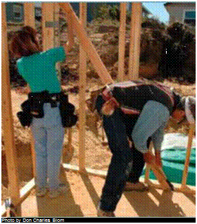
The wall-framing phase of a homebuilding project is an exciting one. Piles of lumber scattered around a flat platform are soon assembled into a complex skeleton that defines the shape and size of a home’s interior spaces. For the first time, it’s possible to experience the look and feel of a new house. We’re still a long way from move-in, but the completed frame is a dramatic step forward.

Framing walls requires an abundance of energy, good teamwork, and real presence of mind. As you’ll see on the following pages, it takes quite a few steps to get the walls up and ready for roof trusses. Wall locations must be chalked out on the slab or subfloor; plates must be scattered; headers, rough sills, cripples, and trimmers must be cut; plates must be marked; and the pieces must be nailed together. After the walls are nailed together, they must be raised, braced, connected, plumbed, lined, and sheathed. It all happens fast, though, and before you know it, there’s a house standing where there wasn’t one before.

Подпись:Подпись: Photo by Don Charles Blom As a novice carpenter, I was often afraid that I would make a huge mis­take while doing wall layouts. Transferring measurements from the building plans to the floor sheathing or slab seemed like a precise and unforgiving science, the principles of which I didn’t fully understand. I knew that once the house was framed, the wall-layout lines would be real spaces—bedrooms, bathrooms, and kitchens—so accuracy seemed critical. After laying out a few houses, however, I learned that, as with most other aspects of carpentry, wall layout just needs to be close—normally within 1/4 in. tolerance—not accurate to a machinist’s or scientist’s tolerances. After I realized that, I was able to relax and get on with the work.

Magnesium-Based Cements

Before the widespread use of Portland cement, magnesium oxide-based cements were among the world’s most popular cement products. By the late 19th century, the use of Portland cement had spread around the world. Although Portland cement has now essentially cornered the market, it has some inherent drawbacks when compared to the magnesium oxide-based cements used by our ancestors. Portland cement manufacturers are currently allocating enormous R&D funding to overcoming deficiencies that impact the envi­ronment, human health, and the strength, dura­bility, and usability of Portland cement. Billions of dollars are being spent in an effort to make Port­land cement do what magnesium phosphate – and magnesium oxychloride-based cements do natu­rally.

No one ever purposely set out to make a prob­lematic cement; quite the opposite. When Joseph Aspdin invented his water-activated Portland ce­ment in his Leeds, England, kitchen in 1824, it seemed to be a viable and exciting advance in ad­dressing the needs of the Industrial Revolution, which was hungry for construction materials. His
new product was convenient to use and the raw materials to make it were in abundant supply.

Portland cement is created by heating raw ma­terials to 2,700 degrees Fahrenheit to create clin­kers. It is common knowledge that the worldwide production of Portland cement, which is increas­ing at a rate of 5 percent annually, currently creates as much as 12 percent of the greenhouse gas emis­sions responsible for global warming.

Some of the most harmful effects of concrete made with Portland cement come when it is "en­hanced" with plastics. The concrete never cures, or does so extremely slowly, which may enhance the strength of the concrete but not the health of a building’s occupants. Furthermore, concrete treated with these plastics outgasses and is toxic, particularly when it is mixed with mold. The high temperatures used in the production of Portland cement make it extremely thirsty for water (hydro­philic), causing a number of problems including the promotion of mold growth.

In many buildings today, 50 to 90 percent by weight of a solid concrete envelope is involved in holding up its own "dead weight."ln the future, the

Other recycled materials such as crushed brick are highly absorbent and may have been exposed to atmospheric pollutants prior to being used in concrete. Aggregate that is free of toxins and acquired odors should be speci­fied as follows:

fly ash (unless it is possible to verify that it contains no heavy metals or toxic sub­stances), cinder, and volcanic material (other than pumice). The contractor shall verify the aggregate content with the con­crete supplier prior to pouring.

• Only clean, natural mineral aggregates are acceptable. The following are un­acceptable aggregates: crushed brick, crushed sandstone, crushed concrete slag,

Admixtures

Many different types of admixtures may be added to the concrete mix to modify various

use of ultra-high-strength magnesium oxide ce­ments could reduce the use of structural cement materials significantly, thereby increasing the per­centage of more insulative, nonstructural infill elements and creating far more energy-efficient envelopes.

Magnesium cements have consistently proven to be superior to Portland cement in strength, versatility, and environmental integrity. Yet until recently magnesium cements had virtually fallen into disuse over the past 175 years. A brief history of magnesium cements will explain why these ancient building materials are of such great his­toric importance and, more importantly, why they may now hold the key to the future of worldwide sustainable building practices. This cement al­ternative (often called ceramic cement) provides unique advantages over Portland cement.

Blends of magnesium oxide were used in an­cient times in Germany, France, Mexico and Latin America, Switzerland, India, China, and New Zea­land, among other countries. The Great Wall of China and many of the stupas in India, still stand­ing today, were made with magnesium-based cements. Ancient European artisans used a timber frame with magnesium oxide infill in construct­ing homes. No gaps are visible in the 8oo-year-old walls that remain in use.

Magnesium deposits exist in abundance in ev­ery corner of the Earth and cover roughly 8 per­cent of its surface. Depending on where they are mined, magnesium oxide cements require only 20 to 40 percent of the energy used to produce Port­land cement.

Magnesium-based cements have exceptional health-promoting properties for the occupants of homes in which they are used as a building ma­terial. For example, research at Argonne National Laboratories has documented that occupants of homes made with traditional cow dung and mag­nesium oxide located right next to the Chernobyl nuclear power plant had less radiation sickness from the nuclear accident than any other group. Occupants of modern stud frame and concrete homes, even miles away, succumbed at higher rates to radiation sickness.

These natural cements bind exceptionally well to all things cellulose (such as plant fibers

properties. For example, air entrainment ad­mixtures disperse air bubbles throughout the concrete to improve resistance to freezing and thawing. Water reducing admixtures decrease the amount of water required. Retarders and accelerators modify the setting time of con­crete. Super plasticizers allow for lower water to cement ratios. They frequently contain sul – fonated melamine, formaldehyde conden­sates, sulfonated naphthalene, and other po­tentially harmful ingredients.

Water reducing agents and air entrainment

admixtures are frequently added to concrete mixtures even when not specifically requested. The exact ingredients of an admixture are usu­ally proprietary. Although admixtures gen­erally make up a very small portion of the concrete and do not pose a significant prob­lem to any but the most sensitive individuals, they can be completely eliminated if concrete work is scheduled for warm weather and if the concrete supplier is aware of this requirement. Even with admixtures, concrete must never be poured on frozen soil or when there is a risk

and wood chips) and are often referred to as living cements. Although the cost of magnesium oxide cement is currently considerably higher than that of Portland cement, a wide variety of indigenous rock, plant and wood fibers, and other cellulose granules can be added to it as aggregate, extend­ing the basic cement material by up to 95 percent and thereby reducing its cost. This is in sharp con­trast to Portland cement, which repels cellulose.

Magnesium-based cements commonly achieve compressive strengths of 9,000 to 45,000 pounds per square inch and tension strength of over 800 pounds per square inch, many times stronger than conventional concrete. Combined with clays and cellulose, magnesium oxide forms cements that "breathe" water vapors, a significant plus. The clay in magnesium oxide balances and enhances the movement of moisture. The material never rots because it always expels moisture.

Magnesium-based cements are completely nonconductive of electricity, as well as heat and cold, and have been used for flooring for radar sta­tions and hospital operating rooms.

Until the early 1930s almost ail terrazzo floors were made with magnesium phosphate or mag­nesium oxychloride. These materials were used extensively throughout the United States until Portland cement offered what appeared at the time to be a less costly, more user-friendly alter­native. The successful manufacture, marketing, and proliferation of Portland cement occurred at a time when energy was cheap and public aware­ness of environmental health concerns was virtu­ally nonexistent.

Recently magnesium-based products have become available from several sources:

Argonne National Laboratory (anl. gov) and others have now licensed firms to market magne­sium-based cements underthe nameCeramicrete. These companies have patents on their products. US Gypsum, the original American maker of Port­land cement, is also introducing magnesium oxide as a nontoxic accelerant and additive. Aquacast is one magnesium oxide product being marketed by US Gypsum.

Grancrete, a spray-on structural cement, has been developed by scientists at Argonne Na­tional Laboratory and Casa Grande LLC as one of

Подпись: that frost may penetrate under the slab while it cures. If you wish to avoid additives, you must specify this. The following is a sample specifi-cation: Подпись: ment and water reducing agents, accelerants, and retardants. Air entrainment is acceptable for garage slabs.

• No admixtures shall be used in the con­crete. It is the contractor’s responsibil­ity to comply with the necessary climatic parameters so that required strengths and finishes are obtained without additives. Verify with the supplier that all concrete is free of admixtures, including air entrain­

Thermal Conductivity Sensors

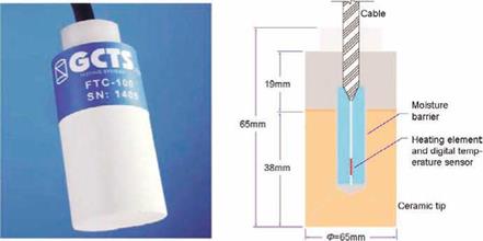
Thermal conductivity sensors (TCS) are used to indirectly relate matric suction to the thermal conductivity of a porous medium embedded in a mass of unsaturated soil. Any change in the soil suction results in a corresponding change in the water content of the porous medium (governed by its characteristic curve). The thermal conductivity of a rigid porous medium is a direct function of the water content. Therefore, if the thermal conductivity of the porous medium is measured, the matric suction of the soil may be indirectly determined by correlation with a predetermined calibration curve. Figure 3.14 shows the main components of a modern commercial TCS.

Thermal Conductivity Sensors

Fig. 3.14 Picture and schema of a thermal conductivity matric suction sensor (TCS). Reproduced with permission from GCTS Testing Services

Some disadvantages usually imputed to the old-fashioned TCS included the prob­lems associated with drift, and, for many sensors, deterioration in the sensor body over time, as well as uncertainties concerning the drying and rewetting processes due to hysteretic effects in the sensor calibration. But most of these problems have been resolved. The major advantages of the more recent TCS include the relative ease with which the sensors may be set up for automated data acquisition, their relatively low cost and their present capability to measure matric suction over a wide range (0-1200 kPa). Figure 3.15 shows some laboratory soil suction measure­ments carried out with both tensiometers and TCS, where tensiometer failures due to cavitation were noticeable. For further details regarding TCS see Rahardjo & Leong (2006).

COMPOSITE FLOOR TRUSSES

COMPOSITE FLOOR TRUSSES

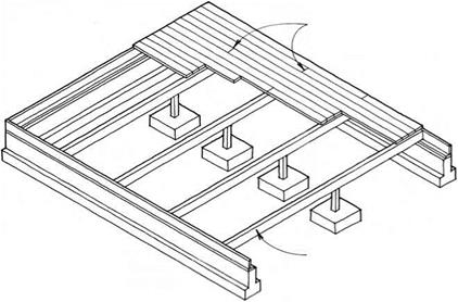
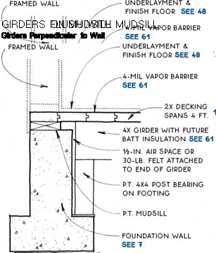
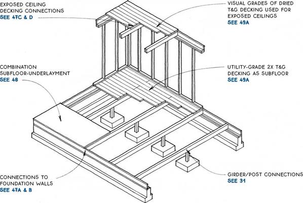
Girder systems may be designed with either dimen­sion or laminated lumber. They are most common in the Northwest, where dimension timber is plentiful. Girder floor systems are similar to joist floor systems except that girders, which are wider than joists, can carry a greater load for a given span and therefore can be spaced at wider intervals than joists. Girders are typically placed on 48-in. centers, so long-spanning subfloor materials such as 2-in. T&G decking or lVs-in. combination subfloor-underlayment are required (see 48).

When used over crawl spaces, girders may be sup­ported directly on posts. Over a basement, a girder system may be supported on posts or may bear on a wall or a beam like a joist system. At upper floor levels, girder systems are often used in conjunction with an

GIRDER SPANS

Size, species, grade, and spacing

Span (ft.)

4 x 6 Douglas-fir #2 @48 in. o. c.

8.6

4 x 8 Douglas-fir #2 @48 in. o. c.

11.3

4 x 10 Douglas-fir #2 @48 in. o. c.

14.4

4 x 12 Douglas-fir #2 @48 in. o. c.

17.6

exposed T&G decking ceiling. These exposed ceilings can make wiring, plumbing, and ductwork difficult.

This table assumes a 40-psf live load, a 10-psf dead load, and a deflection of L/360. The table is for esti­mating purposes only. No. 2 Douglas-fir is most preva­lent in regions where girder systems are most frequently used.

) GIRDER-FLOOR SYSTEMS

FRAMED WALL
COMPOSITE FLOOR TRUSSESПодпись: NOTE DECKING DOES NOT PROVIDE STRUCTURAL DIAPHRAGM REQUIRED AT UPPER FLOORS. USE PLYWOOD UNDERLAYMENT OR OTHER METHOD TO TRANSFER LATERAL LOADS. Подпись:COMPOSITE FLOOR TRUSSES

COMPOSITE FLOOR TRUSSES

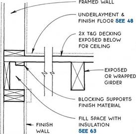
UNDERLAYMENT &

FiNiSH FLOOR SEE 48

2X T&G DECKiNG EXPOSED BELow

for ceiling

exposed or wrapped girder

blocking applied between and to sides of girders supports WALL finish.

note

Подпись: GIRDERS WITH EXPOSED DECKING 2nd Floor: Girders Perpendicular to Wall Подпись: GIRDERS WITH EXPOSED DECKING 2nd Floor: Girders Parallel to Wall

2X T&G decking may BE SANDED To МАКе FiNiSH floor, but this is advisable only with very dry decking. dust filtration from upper to lower floor & sound transmission between floors MAY occur with THIS DETAIL.

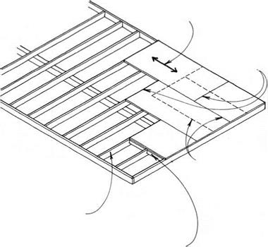
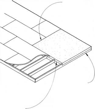
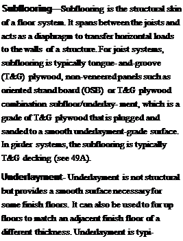
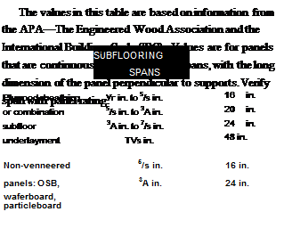
Подпись: Subflooring—Subflooring is the structural skin of a floor system. It spans between the joists and acts as a diaphragm to transfer horizontal loads to the walls of a structure. For joist systems, subflooring is typically tongue- and-groove (T&G) plywood, non-veneered panels such as oriented strand board (OSB) or T&G plywood combination subfloor/underlay- ment, which is a grade of T&G plywood that is plugged and sanded to a smooth underlayment-grade surface. In girder systems, the subflooring is typically T&G decking (see 49A). Underlayment- Underlayment is not structural but provides a smooth surface necessary for some finish floors. It can also be used to fur up floors to match an adjacent finish floor of a different thickness. Underlayment is typi- COMPOSITE FLOOR TRUSSES
Подпись: OFFSET JOiNTS OF SUBFLOOR & UNDERLAYMENT PANELS.

Подпись: Subfloor typeПодпись:

COMPOSITE FLOOR TRUSSES COMPOSITE FLOOR TRUSSES

COMPOSITE FLOOR TRUSSEScally plywood, particleboard, or hardboard.

TECHNICAL

INFORMATION

COMPOSITE FLOOR TRUSSESSUBFLOORING & UNDERLAYMENT

Plywood & Non-Veneered Panels

Typical T&G Decking Sections

Подпись:Подпись: GIRDERCOMPOSITE FLOOR TRUSSESПодпись: NOTE GLUE DECKING TO GIRDERS WITH CONSTRUCTION ADHESIVE TO MINIMIZE FLOOR SQUEAK. REFER TO WESTERN WOOD PRODUCTS USE BOOK FOR SPAN INFORMATION. 2X6 v-JOINT IS MOST.

commonly used ON

upper FLOORS TO MAKE EXpOSED

ceilings below. most species

WILL SpAN 4 FT.

2X8 uTILITY IS

used primarily as subfloor over crawl spaces

OR BASEMENTS & IS OFTEN INSTALLED GREEN. IT WILL SpAN 4 FT. IN MOST FLOOR SITuATIONS.

COMPOSITE FLOOR TRUSSES3X AND 4X LAMINATED IS uSED MOSTLY AT ROOFS TO MAKE EXpOSED cEILINGS BELOW, BuT ALSO AS FLOORING.

decking is end matched FOR random-length application & IS available pREFINISHED IN 3X6, 3X8, 4X6, & 4X8 sizes. IT SpANS up TO 14 FT. FOR RESIDENTIAL FLOOR LOADS.

COMPOSITE FLOOR TRUSSES

SUBFLOORING

T&G Decking


COMPOSITE FLOOR TRUSSESCOMPOSITE FLOOR TRUSSES

Подпись:Подпись: CONCRETE SuBFLOOR/ FOUNDATION SEE 50A, B & c
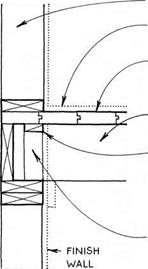
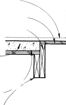
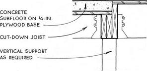
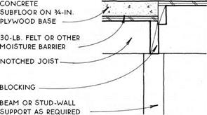
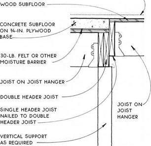
A small part of the subfloor may need to be concrete to support tiles or for a passive-solar mass floor at a south edge. The structure under the concrete must be lowered in order to accommodate the extra thickness of the concrete, typically 2Yi in. to 3 in. Use plywood that is rated to cany the load of wet concrete, usually 3/4 in. (min.).

In the case of a tiled floor, the complications of adjusting the structure to accommodate a thick con­crete subfloor may be avoided by using a Vw in. thick glass-fiber-reinforced cement board over the surface of the typical wood subfloor. Check with the tile manufac­turer for recommendations.

concrete

SuBFLOOR/HEADER

JOIST

SEE 51A & B


NOTE:

FOR THIN-MASS FLOORS SEE 510 & D


SUBFLOORING

Concrete


COMPOSITE FLOOR TRUSSES

Подпись: WOOD & FOUNDATiONПодпись: P.T. MUDSiLLCOMPOSITE FLOOR TRUSSESCOMPOSITE FLOOR TRUSSES

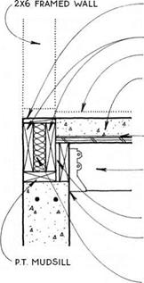
Подпись: NOTE; FOR 2X4 WALL, PLACE INSULATION BETWEEN DOUBLE RiM JOiST & P.T. HEADER JOiST.

FRAMED WALL

FURRiNG SAME THiCKNESS AS WOOD SUBFLOOR

P. T. MUDSiLL

FiNiSH Floor

concrete subfloor ON

3A-iN. PLYWOOD BASE; LEVEL AND THiCKNESS VARY WiTH FiNiSH MATERiAL.

30-LB. FELT OR OTHER MOiSTURE BARRiER

iNSULATiON

JOiSTS BEAR ON LEDGE iN FOUNDATiON WALL OR ON LEDGER OR PONY WALL SEE 12D

FURRiNG SAME THiCKNESS AS WOOD SUBFLOOR

DOUBLE RiM JOiSTS FiNiSH FLOOR

CONCRETE SUBFLOOR ON 3A-IN. PLYWOOD BASE;

LEVEL AND THiCKNESS VARY WiTH FiNiSH MATERiAL.

30-LB. FELT OR OTHER MOiSTURE BARRiER

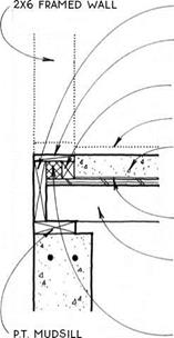
JOiSTS HUNG FROM P. T. HEADER JOiST RiPPED TO BEAR ON FOUNDATiON WALL.

SPACER BLOCKS AT 16 iN. O. C.

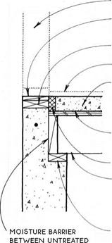
MOiSTURE BARRiER BETWEEN UNTREATED JOiSTS & FOUNDATiON

insulation

COMPOSITE FLOOR TRUSSES

CONCRETE SUBFLOOR AT EXTERIOR

Full-Depth Joists below Mudsill

CONCRETE SUBFLOOR AT EXTERIOR

Full-Depth Joists/Alternative

NOTE

FOR CONDITION AT EXTERIOR WALL SEE 50A & B.


COMPOSITE FLOOR TRUSSES

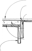
RIM JOiST


FURRiNG SAME THiCKNESS AS WOOD SUBFLOOR

FURRiNG

FiNiSH FLOOR

CONCRETE SUBFLOOR ON 3A-1N. PLYWOOD BASE;

LEVEL AND THiCKNESS VARY WiTH FiNiSH MATERiAL.

30-LB. FELT OR OTHER MOiSTURE BARRiER

JOiSTS CUT OR SIZED DOWN TO ACCOMMODATE DEPTH OF CONCRETE SUBFLOOR

INSULATION


PLYWOOD OR OTHER WOOD SUBFLOOR

TYPICAL JOiSTS


COMPOSITE FLOOR TRUSSES

NOTE

DECREASE SPAN AND/OR SPACING OF SIZED-DOWN JOiSTS SUPPORTING CONCRETE.


COMPOSITE FLOOR TRUSSESCOMPOSITE FLOOR TRUSSESCOMPOSITE FLOOR TRUSSES

COMPOSITE FLOOR TRUSSES

CONCRETE SUBFLOOR AT EXTERIOR

Cut-Down Joists on Mudsill

CONCRETE SUBFLOOR AT INTERIOR

Edge Parallel to Joists/2 Details

NOTE

FOR CONDiTiON AT EXTERiOR WALL SEE 50A OR B.


FiNiSH FLOOR

COMPOSITE FLOOR TRUSSES


COMPOSITE FLOOR TRUSSES

PLYWOOD OR OTHER


FiNiSH FLOOR

COMPOSITE FLOOR TRUSSES


COMPOSITE FLOOR TRUSSES

COMPOSITE FLOOR TRUSSES

д) CONCRETE SUBFLOOR AT INTERIOR

Edge Perpendicular to Joists

CONCRETE SUBFLOOR AT INTERIOR

Edge Perpendicular to Joists: Alternative Details

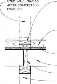
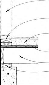
Подпись: DOUBLE 2X P.T. PLATE SERVES AS SCREED & ALLOWS UTILITIES TO PASS THROUGH FLOOR SYSTEM AT WALL.Подпись: 3-IN. CONCRETE SUBFLOOR ON 3A-IN. PLYWOOD BASECOMPOSITE FLOOR TRUSSESПодпись: 30-LB. FELT OR OTHER MOISTURE BARRIER JOIST BLOCKING STRUCTURE BELOW AS REQUIRED Подпись: STUD WALL FRAMED AFTER cONcRETE iS FINISHED Подпись: DOUBLE 2X P.T. PLATE SERVES AS SCREEDПодпись: 3-IN. CONCRETE SUBFLOOR ON 3A-IN. PLYWOOD BASECOMPOSITE FLOOR TRUSSES30-LB. FELT OR OTHER MOISTURE BARRIER

JOIST

P. T. MUDSILL (OR TOP PLATE IF THIN-MASS SUBFLOOR IS AT UPPER STORY)

NOTE

THIS DETAIL IS USED TO PROVIDE MASS TO A LARGE AREA OF FLOOR FOR SOLAR GAIN.

NOTE

IF THE CONCRETE IS TO BE EXPOSED, THE DOUBLE PLATE MAY BE OMITTED FOR EASE OF TROWELING. THE STUD WALL MAY THEN BE SHOT TO CONCRETE SEE 24C

THIN-MASS SUBFLOOR

THIN-MASS SUBFLOOR

COMPOSITE FLOOR TRUSSES

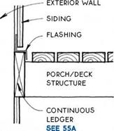
Подпись: EXTERiOR WALL _ SiDiNG SPACE ALLOWS WATER TO PASS. PORCH/DECK STRUCTURE Подпись: CONNECTORS AT iNTERVALS SEE 54B & CCOMPOSITE FLOOR TRUSSES

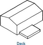
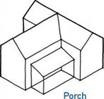
Porches and decks are traditional and useful addi­tions to wood-frame structures. They provide a transi­tion between indoors and out, allowing people to pause upon entering or leaving, and they extend the building to include the out-of-doors. Porch and deck floors must be constructed differently from interior floors in order to withstand the weather. The connection between porch and deck floors and the building itself is espe­cially critical in keeping moisture out of the main struc­ture. Because of constant exposure to the weather, this connection must be detailed in such a way that it can be repaired or replaced.

COMPOSITE FLOOR TRUSSES

The floors of porches and decks can be grouped into two major types: those that are waterproof and thus act as a roof protecting the area below, and those that are open and allow water to pass through.

Waterproof

Porch/Deck

Floor

COMPOSITE FLOOR TRUSSES

Open

Porch/Deck

Floor

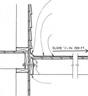
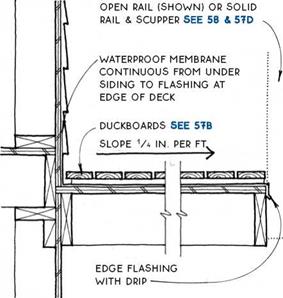
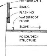
Waterproof porch—A waterproof porch or deck floor can be treated like a flat roof. As shown in the drawing below, flashing (or the roofing material itself) must be tucked under the siding to catch water running down the side of the building, and the floor (roof) sur­face must be sloped away from the building (see 56A). The framing for waterproof decks over living spaces needs proper ventilation (see 205A).

COMPOSITE FLOOR TRUSSES

Open porch—In an

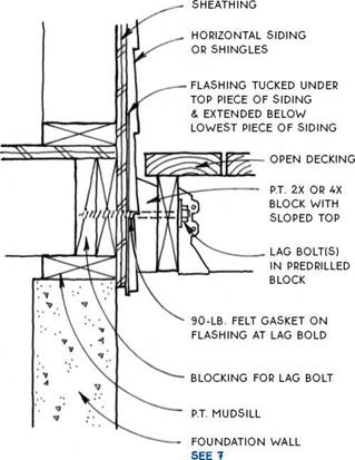
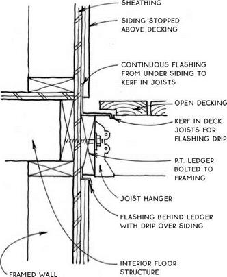
open porch or deck floor, the parts that connect it to the main structure are exposed to the weather, yet need to penetrate the skin of the wall. This connection can be accomplished by keeping the porch/ deck structure away from the exterior wall and attaching it only at intervals with spaced connectors (see 54B & C).

Alternatively, a continuous ledger may be bolted to the wall and flashed (see 55A & B).

(g) PORCHES & DECKS

COMPOSITE FLOOR TRUSSES

Porches and decks are exposed directly to the weather in ways that the main part of the structure is not. Consequently, the wood used in porches and decks is much more susceptible to expansion and contraction, twisting, checking, and rotting. A special strategy for building porches and decks is therefore appropriate.

Weather resistance – Elements of porches and decks that are likely to get wet should be constructed of weather-resistant materials. Virtually all the material required to make a new porch or deck is now available in pressure-treated lumber. Weather-resistant woods like cedar or redwood are also appropriate.

Connectors – At least once a year, joints that are exposed to the weather will shrink and swell, causing nails to withdraw and joints to weaken. Joints made with screws or bolts will therefore outlast those made with nails. For joist connections, use joist hangers or angle clips.

Joist hangers are made of galvanized steel, which should not be adversely affected by exposure to the weather. Galvanized steel deteriorates relatively quickly, however, when combined with pressure – treated lumber, especially when moisture is added to the mix. Therefore, always use connectors with the longer-lasting hot-dip galvanized finish. Also, consider the use of weather-resistant wood species for use with galvanized hangers.

Fasteners such as nails and deck screws should be galvanized. Stainless steel screws are also available and will give the longest life.

Framing—Areas between adjacent wood members collect moisture and are especially prone to rot. Even pressure-treated lumber can rot in this situation. Avoid doubling up members in exposed situations. It is better to use a single large timber where extra strength is required, as shown in the drawing at right.

Where wood must touch another surface, make the area of contact as small as possible and allow for air cir­culation around the joint.

Wood decking—Because decking is oriented horizon­tally, it has a relatively large exposed surface to collect and absorb moisture. This moisture will tend to make the decking cup. Most references suggest installing flat – grain wood decking (and rail caps) with the bark side down because boards will cup in the right direction to shed water as they season.

COMPOSITE FLOOR TRUSSES

Unseasoned (wet) Seasoned (dry) Wet

However, if dry (seasoned) decking is installed with the bark side down, the boards will cup in the wrong direction when they get wet. Therefore, dry decking boards should be installed with the bark side up so that the boards will shed water if they cup.

COMPOSITE FLOOR TRUSSES

Seasoned Wet

Synthetic decking—There is a new generation of synthetic decking made of reclaimed hardwood and recycled plastic. This material holds up in exposed con­ditions, is not harmed by rot or insects, and is extremely consistent and stable. The decking is not as stiff as sawn lumber, so it requires closer joist spacing. It can be fastened to framing with conventional methods and is available in standard sizes from 1×6 to 2×8.

Because the decking does not absorb water, thermal expansion is more of a concern than warping or cup­ping. The decking requires no sealers or preservatives and is manufactured with a nonskid surface. It is dis­posable (no toxins).

Painting—Sealers and preservatives will extend the life of porches and decks. Special attention should be given to end grain and to areas likely to hold moisture. Stains will outlast paints. Special porch and deck paints are available for use where exposure to the weather is not severe.

@ PORCH & DECK CONSTRUCTION
COMPOSITE FLOOR TRUSSESCOMPOSITE FLOOR TRUSSES

Подпись: st

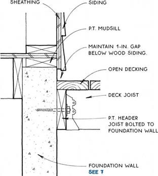
(g) OPEN DECK/FOUNDATION WALL

pN OPEN DECK/WOOD WALL

Floor : Horizontal Siding or Shingles
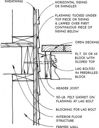
COMPOSITE FLOOR TRUSSESNOTES

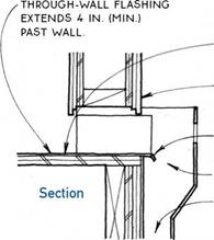
FLASHiNG EXTENDS 8-iN. MiNiMUM PAST BOTH SiDES OF BLOCK SPACERS.

iNSTALL Spacer BLocKS SiMULTANEOUSLУ with SiDiNG & FLASHING, Then iNSTALL Deck.

opEN DEcKiNG LAID DiAGONALLУ AcRoSS JoiST sysTEM acts as a DiAPHRAGM, wHicH мау eliminate the need for bracing porch supports.

DETAILS show level of DEcK SLiGHTLy BELow level of FiNiSH floor. iN SNow couNTRy, adjust deck level and flashing height to account for snow buildup.

spaced decking is often used for the floor of a screened porch. in this case, the decking must be installed over insect screening.

OPEN DECK/WOOD WALL

2nd Floor: Horizontal Siding or Shingles
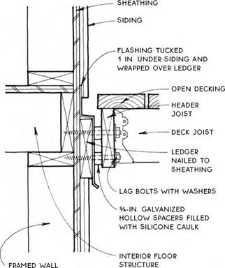
COMPOSITE FLOOR TRUSSESCOMPOSITE FLOOR TRUSSES

(g) OPEN DECK/WOOD WALL

OPEN DECK/WOOD WALL

Alternative Detail

OPEN RAiLiNG BOLTED TO JOiSTS OR AS EXTENSiON OF VERTiCAL SUPPORT SEE 59A


SOLID RAILING Of STuDS & SIDING SEE 55A


OPEN DEcKiNG


OPEN DECKING


DEcK JOiST

supported ву

JOiST HANGER ON HEADER JOiST


DECK JOiST SUPPORTED ВУ JOiST HANGER ON HEADER JOiST


HEADER JOiST BOLTED TO STuDS


HEADER JOIST SCREWED OR BOLTED TO VERTICAL SUPPORTS


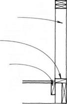
FLASHING TucKED 1 in. under SIDING AND BEHIND HEADER JOiST


skirting


stud wall, wood

POST, OR Other

vertical support


stud WALL, WOOD POST, OR OTHER

vertical support


COMPOSITE FLOOR TRUSSESCOMPOSITE FLOOR TRUSSESCOMPOSITE FLOOR TRUSSES

OPEN DECK/OPEN RAILING

OPEN DECK/SOLID RAILING

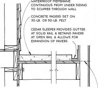
Подпись:Подпись: SLIP SHEET AS REQUIRED WITH SOME COATINGS.COMPOSITE FLOOR TRUSSESПодпись: ELASTOMERIC. BITUMINOUS. OR OTHER WATERPROOF MEMBRANE OR COATING.- EXTEND COATING FROM UNDER SIDING TO EDGE OF DECK.Подпись: HEADER JOIST BOLTED TO FRAMING MINIMIZES MOVEMENT.COMPOSITE FLOOR TRUSSESПодпись: General CharacteristicsПодпись: ДЛ WATERPROOF DECKS
NOTES

WATERPROOFiNG CAN BE PROTECTED FROM ABRASiON ВУ ADDiTiON OF WOOD OR CONCRETE-PAVER SURFACE, SEE 57A, в & C

slope may BE ACHiEvED By SLOpING JOiSTS OR,

where a level surface is required below, ву ripping joists or adding furring strips.

EDGE flashing WITH DRip extends 4 in. under waterproofing.

attachment of railings see 58 & 59

rim joist deeper than

DECK JOISTS TO FORM DRip

stud wall, WOOD post, OR other vertical support
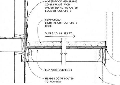
COMPOSITE FLOOR TRUSSESNOTE

if rail is solid, slope

CONCRETE TO SCuppERS FROM ALL DIRECTIONS. see 57D

NOTE

alternative flashing detail below will provide A FORM FOR EDGE OF CONCRETE.

COMPOSITE FLOOR TRUSSES

EDGE FLASHING WITH DRip

extends 4 in. under waterproof membrane.

rim joist deeper than deck

JOISTS TO FORM DRip

stud wall, WOOD post, OR other vertical support

COMPOSITE FLOOR TRUSSES

LIGHTWEIGHT-CONCRETE PORCH DECK

COMPOSITE FLOOR TRUSSES

COMPOSITE FLOOR TRUSSES

UNDERSIDE OF SLEEPERS.


NOTE

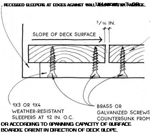
DUCKBOARD DECKS ARE GENERALLY HELD iN PLACE ВУ GRAViTY. THEY SHOULD NOT BE USED iN AREAS OF EXTREMELY HiGH WiNDS.


COMPOSITE FLOOR TRUSSES

COMPOSITE FLOOR TRUSSES

DUCKBOARD DECK

Open Rail Shown

DUCKBOARD DECK

Detail

COMPOSITE FLOOR TRUSSES

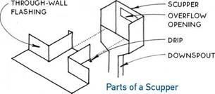
Подпись: LOW POINT IN DECK FLOOR SIDING FORMS DRIP OVER WALL OPENING Подпись: EXTEND FLASHING DRIP BEYOND SIDING SCUPPER DOWNSPOUT COMPOSITE FLOOR TRUSSES

COMPOSITE FLOOR TRUSSES
Подпись: SCUPPER

NOTE j

THIS DETAIL IS NOT SCUPPER THROUGH

RECOMMENDED IN SOLID RAIL SEE 57D У

AREAS OF SEVERE FREEZING WEATHER.

Подпись:Подпись: BLOCKiNG FOR SIDING NAILINGПодпись: BLOCKING FOR SUBFLOOR NAILING NOTE PROVIDE BLOCKING BETWEEN JOiST AT RAILING STUD IF RAILING IS PARALLEL TO JOiST SYSTEM. COMPOSITE FLOOR TRUSSESПодпись: RAILING/WALL CONNECTION SEE 105AПодпись:COMPOSITE FLOOR TRUSSESBecause they make continuous contact with the porch or deck floor, solid railings are relatively simple to design and construct to resist overturning due to lat­eral force. For short railing spans (up to 8 ft. long) sup­ported at both ends by a column, a wall, or a corner, the simplest framing (see the drawing below) will suffice because the top edge may be made stiff enough to span between the two rigid ends.

Longer railings or railings with one or both ends unsupported must be designed to resist lateral forces by means of a series of vertical supports firmly secured

to the porch or deck floor framing (see the drawing below). This means, of course, that the porch floor framing itself must be solidly constructed.

DOUBLE TOP PLATE, SUPPORTED AT BOTH ENDS, MAY BE STiFFENED FURTHER BY RAiL CAP. —-

SOLE PLATE NAiLED TO SiMPLE DECK CONSTRUCTiON

cONTiNuOuS RAiLiNG STuD notched over Rim JOiST & NAiLED TO JOiST System RESiSTS OvERTuRNING.

The same results may be achieved in a porch or deck built over a living space by using a balloon frame system with porch-rail studs continuous through to the wall below.

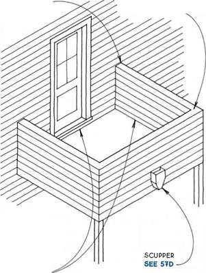
Waterproof deck with solid railing—Waterproof decks surrounded by a solid railing must be sloped to an opening in the railing. This opening can be a flashed hole in the wall, or scupper, as shown here, or it can be a gap in the wall that accommodates a stairway or walk. (Avoid directing water to walkways in climates with freezing temperatures.) The opening should be located away from the main structure of the building, and the floor should pitch toward the opening from all directions. In some cases, a second opening or overflow should be provided to guarantee that water won’t build up if the primary drain clogs.

wall/deck

connection

IS SAME AS

railing/deck connection see

DRAWINGS AT LEFT

Open deck with solid railing—Open decks sur­rounded by a solid railing are simple to drain since water will pass through the floor surface (see 55D). Care should be taken to provide adequate drainage from any surface below the deck.

COMPOSITE FLOOR TRUSSES

Ace

WHETHER YOU’RE AN EXPERIENCED BUILDER, A HABITAT VOLUNTEER, ora novice carpenter, the wall-framing phase of a homebuilding project is especially exciting. Piles of lumber scattered around a flat platform are soon assembled into a complex skeleton that defines the shape and si/.e of a homes interior spaces. For the first time, it’s possible to experience the look and feel of a new house, identifying where bed­rooms and bathrooms will be and enjoying the view through rough window open­ings. We’re still a long way from move-in condition, but the completed frame is a dramatic step forward.

Although quite gratifying, framing walls is also hard, intense work. It requires an abundance of energy, good teamwork, and real presence of mind. As you’ll see on the following pages, it takes quite a few steps to got the walls up and ready for roof trusses. Wall locations must be chalked out on the slab or subfloor; plates must be scattered; headers, rough sills, cripples, and trimmers must be cut; plates must be marked; and the pieces must be nailed together. After the walls are nailed together, they must be raised, braced, connected, plumbed, lined, and

Подпись: STEP BY STEP

1 Lay Out the Walls

2 Plate the Walls

3 Count and Cut the Headers, Rough Sills, Cripples, and Trimmers

4 Mark the Plates

5 Build the Walls

6 Raise the Walls

7 Plumb and Line the Walls

8 Install and Plumb Door and Window Trimmers

9 Sheathe the Walls

7 A


Ace

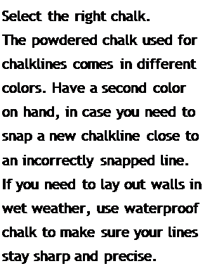
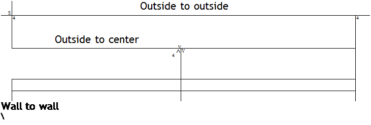
Подпись: Helping HandПодпись: Select the right chalk. The powdered chalk used for chalklines comes in different colors. Have a second color on hand, in case you need to snap a new chalkline close to an incorrectly snapped line. If you need to lay out walls in wet weather, use waterproof chalk to make sure your lines stay sharp and precise. Подпись: 1 WALL DIMENSIONS ON PLANS Подпись: S Outside to outside 4 Outside to center V 4 4 ^ V Wall to wall  Подпись: Center to center — Ac-cepter to center is the same as wall to wall. Подпись: Dimensions on plans can be shown in different ways. Make sure you know the beginning aid end points of your measurements before laying out any walls.

sheathed. It all happens fast, though, and before you know it, there’s a house standing where there wasn’t one before.

As a novice carpenter, I was often afraid that 1 would make a huge mistake while doing wall layouts. Transferring measurements from the building plans to the floor sheathing or slab seemed like a precise and unforgiv­ing science, the principles of which I didn’t fully understand. I knew that once the house was framed, the wall-layout lines would be real spaces—bedrooms, bathrooms, and kitchens—so accuracy seemed critical. After

4

laying out a few houses, however, I learned that, as with most other aspects of carpentry, wall layout just needs to be close—normally within :4 in. tolerance—not accurate to a

machinist’s or scientist’s tolerances. After I realized that, I was able to relax and get on with the work.

STEP 1 Lay Out the Walls

I’ve done plenty of house layouts on my own, but its better to tackle this job with a helper or two. The work goes faster when you have someone else to hold the other end of the tape or chalkline. More important, your chances of catching mistakes improve significantly.

Read the building plan

A building plan is a guide, just like a road map. There are symbols and measurements to tell vou what to do (see the illustration on the

4

facing page). You don’t have to visualize every detail on a road map to get from Texas to Maine. Neither do you have to visualize every detail on a plan to be able to build a house. You just have to know how to read the plan, then take it one step at a time.

The most common plan scale uses / in. to equal 1 ft., so l in. on a plan equals 4 ft. on a subfloor. Plan dimensions, however, can be labeled as outside to outside, outside to center, or center to center (wall to wall), so you need to pay close attention to this information (see the illustration at left). For layout purposes, if you encounter an outside to center (o/s toe) dimension, simply add I M in.—half the width of a 2×4—to the overall measurement to obtain the outside to outside measurement, which you can then transfer to the floor. (For a 2×6 wall, add 2і/ in.)

The first layout work involves transferring key information from the building plans to the subfloor or slab. These lavout lines enable

j

you to lay down the top and bottom plates for every wall in the house—a process called plat­ing the walls. With each wall’s top and bottom

RIGID PAVEMENT

Rigid pavement can be constructed with contraction joints, expansion joints, dowelled joints, no joints, temperature steel, continuous reinforcing steel, or no steel. Most generally, the construction requirements concerning these options are carefully chosen by the owner or the public entity that will be responsible for future maintenance of the pave­ment. The types of joints and the amount of steel used are chosen in concert as a strategy to control cracking in the concrete pavement. Often, the owner specifies the construction requirements but requires the designer to take care of other details such as intersection jointing details and the like. It is imperative that a designer understand all of these design options and the role each of these plays in concrete pavement performance.

The category of rigid pavements can be further broken down into those with joints and those without. Jointed reinforced concrete pavement (JRCP) and jointed plain con­crete pavement (JPCP) are the two basic types of jointed concrete pavement. Continuously reinforced concrete pavement (CRCP) has no joints. JRCP is designed for maximum joint spacing permitting cracking between joints and requires temperature steel. JPCP is designed for no cracking between joints; thus, joint spacing is mini­mized and temperature steel is eliminated. Historically, many jointed pavements were constructed without dowelled joints. Past performance of undowelled jointed pavements— with the exception of warm, dry climates or low-volume roadways—has been poor. Where there are more than a few trucks per day, dowels should be considered at con­traction joints. However, low-volume roadways that do not carry significant trucks, such as residential streets, may perform satisfactorily without dowelled joints.

Grading of the Coarse Aggregate Fraction versus the Distribution of Air Voids

Investigations carried out in the Netherlands (Voskuilen, 2000) have proved that the gradation within the coarse aggregate fraction exerts an impact on the distri­bution of voids in a mix. Briefly, the conclusions drawn in the Netherlands are as follows: [25]

6.3.2.2.3 Determining the Size of Active Particles

After exercises in changing ratios within the coarse aggregate fraction, it is time to explore the question of the influence of the size of active particles on the mix. As we remember from Chapter 2, active grains are those making an aggregate structure that carries loads. The problem of actively setting up the SMA skel­eton by particles of a certain fraction—say, 2/4 (or 2/5.6) mm—was discussed there. According to the German approach to SMA, that size of particle could be used for that purpose, though to a limited extent (as the German ratios suggest that in SMA 0/11 only one seventh of all coarse aggregates should be of size 2-5mm). According to the U. S. approach, this size should not be used, although that depends on the maximum size of the SMA aggregates, or NMAS. The lower limit sieve, from which active particles are counted, is called the breakpoint (BP) sieve in the United States.

Подпись: NMAS: 25 mm NMAS: 19 mm NMAS: 12.5 mm NMAS: 9.5 mm NMAS: 4.75 mm Подпись: BP sieve = 4.75 mm BP sieve = 4.75 mm BP sieve = 4.75 mm BP sieve = 2.36 mm BP sieve = 1.18 mm

The adopted classification in the United States—in NAPA SMA Guidelines QIS – 122—imposes lower size limits for coarse (active) particles based on NMAS as follows:

At any rate, coarse particles 2.36/4.75 mm (below 4.75) have been regarded as active ones in SMA 0/9.5 mm. In SMA 0/4.75 mm, the fraction 1.18/2.36 mm is also considered an active one (as are all larger ones). In coarser mixes, aggregates above

4.75 mm are regarded as active.

The selection of the BP sieve influences not only on the shape of the gradation curve but also the properties of SMA mixtures. Generally, the larger the BP sieve, the stronger the predominance of coarse (active) particles in a mix. One can safely say that the coarse aggregate fraction becomes more single sized as the discontinu­ity of gradation becomes stronger. When estimating gradation curves for various BP sieves, the conclusion can be drawn that the larger the BP sieve, the further the position of the breaking point of the gradation curve is moved to the right. And thus one can also say that the larger the BP sieve, the more open the mix and the more binder is required.

Results of some work in the United States (Cooley and Brown, 2006) justify say­ing that raising the size of the BP sieve results in the following consequences to the properties of an SMA mixture because it increases: [26]

• Permeability of the mixture—with the same content of voids in a com­pacted SMA mixture, the permeability is higher with a larger BP (for more on permeability, see Chapter 12).

. Exterior Wall

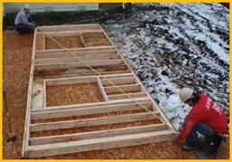
To square a wall, secure the bottom plate as shown, then move the top of the wall until the diagonal dimensions are equal. Once the wall is square, secure it with two nails through the double plate into the floor.

. Exterior WallNail on the inside of the bottom plate so the nails will hold the wall in position while it is being stood. The bottom plate should be nailed so that it’s in line with the wall chalk line. Then, when the wall is raised, it will be in the right position.
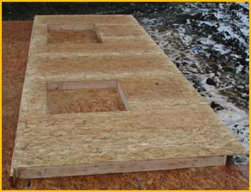
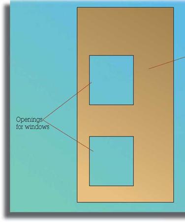
. Exterior WallПодпись: Sheathing: place, cut openings, and nail.Подпись: Wall sheathing. Exterior Wall. Exterior WallCover the entire wall with sheathing, then rout window and door openings with a panel pilot router bit (see illustration). Save the leftover pieces of sheathing for small areas and filling in between floors.
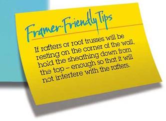
If the first floor exterior walls can be reached from the ground, then the sheathing is not installed until after the walls are plumb and lined (straight and true; see Step 16-Plumb & Line). This eliminates the potential problem of a square wall sitting on a foundation that is not level.

. Exterior Wall

Panel pilot router bit