Exteriors

The exterior і multi­

layered membrane, weatherproofing the house much the way a roof does. In addition to protect­ing underlying elements from damage by sun and wind, the exterior intercepts and directs water away from the underlying sheathing and fram­ing. The visible exterior layer consists of siding and trim. Beneath the siding, ideally, is either building paper or plastic housewrap, which is relatively water repellent. In addition, flashings seal transitions from one material to another or redirect water around potential dams, such as window and door headers, vent fans, and outdoor outlets. Finally, various sealants fill gaps, adhere materials, or cut air infiltration. Of course, win­dows and doors are exterior elements, too. But as “openings” in the exterior, they are the principal subjects of Chapter 6.

Although drain gutters may be considered part of the roof, they are discussed at the end of this chapter because gutters “attach to” and pro­tect the exterior. Gutters also direct water away from foundations, thus reducing moisture there and mold in basements and crawl spaces while preventing excess water from undermining foundations.

As with other building systems, maintenance is crucial. Each autumn after the leaves have fallen and each spring, clean gutters and downspouts; if needed, do this more often to keep them flowing freely. Every year, survey and recaulk building seams as needed. Paint or stain wood siding peri­odically. Trim trees and shrubs so they don’t retain moisture next to the siding or restrict air circulation. Slope the soil away from the founda­tion to help direct water away. Adjust lawn sprin­klers so they don’t spray siding.

It still takes a skilled eye to install siding. For this job, pneumatic nailers, as shown, have largely replaced hammers and drill drivers.


■В? > .. *‘чС* ..

‘■ – иди

* Ы Ужі

1

g wj I As;1′

Weatherproofing Windows

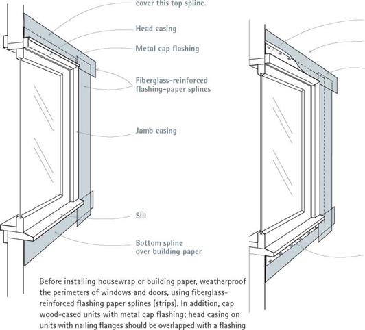
Подпись: WINDOW WITH INTEGRAL NAILING FLANGEWOOD-CASED WINDOW

Building paper will


Nailing flange


Building paper will cover flexible flashing.

Flexible flashing sealing cap flange


Sill flange

over flashing paper


paper spline or sealed with flexible flashing.


image268

Weather Barriers

No matter how well siding is installed, sooner or later water will work its way behind. Typically this happens when storms drive rain into build­ing seams or gaps around doors or windows. But water can also be drawn inward and even upward by capillary action before trickling down behind siding. For these reasons, builders protect exterior sheathing with building paper (15-lb. building paper is most common) or plastic housewraps such as Tyvek® or R-Wrap® to repel water.

Both building paper and plastic housewrap do a good job of reducing air infiltration. That is, both are permeable enough to allow excessive moisture behind the siding to escape, and both are sufficiently water repellent to protect sheath­ing from wind-driven rain. Bottom line: It doesn’t matter whether you use building paper or house – wrap, as long as it’s correctly installed and con­forms to local building codes, which may require
that they are compatible with finish materials. For example, beneath stucco, many building codes require a double layer of Grade D kraft paper or a fortified paper such as Fortifiber’s Super Jumbo Tex® 60 Minute.

Typically, this weatherproofing membrane is installed after windows and doors have been installed and their perimeters weatherproofed with fiberglass-reinforced flashing paper. As shown in "Wood-cased window,” above, building paper overlays cap flashing and fits under the sill flashing. Cap flashing, also called head flashing, is especially important because it redirects water that might otherwise dam behind a door or window head casing, leading to stains and mold on interior surfaces, swollen sashes, peeling paint, and rot.

Replacing all siding, flashing, and building paper is the surest way correct such water-related damage, but if that’s not in your budget, retro-

Подпись: PROTIP Plastic housewrap is slippery, so don't lean unsecured ladders against it. Secure the ladder or, better yet, use scaffolding if you're installing housewrap and siding to a second story. Always install housewrap with its printed side facing out: It's engineered to allow migration of water vapor in one direction only. 1111 fitting flashing around individual windows and doors may do the trick. In that case, cut back the siding far enough around the perimeter of the door or window to install 6-in.-wide flashing paper, as described next.

BRIDGE ENGINEERING

Walter J. Jestings, PE.

Formerly, Bridge Engineer
Parsons Brinckerhoff, Quade & Douglas, Inc.
Atlanta, Georgia

Mahir Sen, P. E.

Professional Associate
PB Americas, Inc.

Newark, New Jersey

This chapter is directed at practical issues of importance in the design and rehabilita­tion of traditional bridge types for short and medium spans. Subjects addressed include characteristics of various bridge types, considerations in their selection, and suggestions for economical design; materials for bridges and bridge decks; bridge deck design, construction, and maintenance; deflection and expansion joints; and bridge bearings. The issues are addressed from a general viewpoint, with the emphasis on what is generally done and why. Detailed design methods are available in other publications. (See R. L. Brockenbrough and F. S. Merritt, Structural Steel Designer’s Handbook, McGraw-Hill, and E. H. Gaylord and C. N. Gaylord, Structural Engineering Handbook, McGraw-Hill.)

LIFE CYCLE COST ANALYSIS OF PAVEMENTS

It is seldom readily apparent which is the most economical rehabilitation method for a particular pavement. Each rehabilitation strategy has unique initial construction costs, performance expectations, and future maintenance needs. What is most economical for one pavement may not be for another. Local costs may differ from one location to another, and material performance expectations may be different from region to region. The only rational way to compare one rehabilitation strategy and another is to perform an economic analysis of the alternative strategies. The method used for such a study is the life cycle cost analysis (see Chap. 10).

It is not good practice to compare a minor pavement rehabilitation strategy and a complete pavement replacement strategy. Even when comparing a new rigid pave­ment and a new flexible pavement, difficult choices must be made concerning the expected performance of each pavement type. Table 3.29 shows a hypothetical example of life cycle cost analysis assuming a 35-year performance period for both alternatives with no salvage values at the end of the period. It is not the intent to show that one pavement type has an economical advantage over another, as many hypothetical assumptions were made in the example. The intent is to indicate the level of information needed to make a life cycle cost analysis, and the information an analysis presents.

Probably the most important consideration in a life cycle cost analysis is the selec­tion of the discount rate used to evaluate the time value of money. It is sometimes defined as the difference between the market interest rate and the rate of inflation. (Article 10.8.2 provides further discussion on this subject.) Because costs are incurred at different times over the life of a pavement, the discount rate is used to convert these costs occurring at different times to equivalent costs in present dollars. In the example

Length: 3.16 mi (5.08 km) Lane number: 5 Lane width: 12 ft (3.66 m) All Lane widths vary; average width of roadway

Dimension,

Item in

sections in curb—no shoulders ■ = 60 ft (18.3 m)

Quantity analysis

Cost analysis

Unit

ALT1

ALT2

Price

ALTl

ALT2

Main lane

AC surface course

1.25

CY

3,862

$46.00

$178,000

AC intermed. course

1.75

CY

5,407

$44.00

$238,000

Bituminous base

7

CY

21,628

$39.00

$844,000

Aggregate base

6

CY

18,539

18,539

$18.00

$334,000

$334,000

JRCP

9

SY

111,232

$22.00

$2,447,000

Asphalt prime coat

SY

44,493

$1.50

$67,000

Subtotal

$2,781,000

$1,661,000

Future maintenance

10 years

Pavement milling

1.50

SY

111,232

$1.20

$133,000

AC surface course

1.25

CY

3,862

$46.00

$178,000

AC intermed. course

1.75

CY

5,407

$44.00

$238,000

20 years

Pavement milling

3.00

SY

111,232

$1.75

$195,000

AC surface course

1.25

CY

3,862

$46.00

$178,000

AC intermed. course

1.75

CY

5,407

$44.00

$238,000

Bituminous base

3

CY

9,269

$39.00

$362,000

Joint repair, 3%

SY

3,337

$35.00

$117,000

Pavement sawing

LF

1,430

$1.20

$2,000

Diamond grinding

SY

111,232

$2.00

$222,000

Transverse joint reseal

LF

49,101

$1.50

$74,000

Longitudinal joint reseal

LF

66,739

$1.50

$100,000

(Continued)


Подпись: 307

Item

Dimension,

in

Quantity analysis

Cost analysis

Unit

ALT1

ALT2

Price

ALTl

ALT2

Future maintenance (cont.)

30 years

Pavement milling

1.50

SY

111,232

$1.20

$133,000

AC surface course

1.25

CY

3,862

3,862

$46.00

$178,000

AC intermed. course

1.75

CY

5,407

5,407

$44.00

$238,000

Subtotal

$515,000

$2,071,000

Grand total

$3,296,000

$3,732,000

Conversions: 1 in = 25.4 mm, 1 yd2 = 8.36 m2, 1 yd3 = 0.765 m3.

AC = asphalt concrete; JRCP = jointed reinforced concrete pavement; CY = cubic yards; SY = square yards; LF = linear feet.


Подпись: 308

LIFE CYCLE COST ANALYSIS OF PAVEMENTS

FIGURE 3.59 Sensitivity analysis showing effect of discount rate selection on life cycle cost of pavement alternatives.

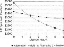
shown in Table 3.29, the discount rate was unrealistically assumed as zero. Figure 3.59 shows the effect of discount rates from 0 to 6 percent. As is typically the case, the analysis is very sensitive to the discount rate. In this example, the rigid pavement pro­vides the lower life cycle cost when the discount rate is less than about 1.7 percent, and the flexible pavement when the rate is higher. It is apparent that the discount rate must be selected with great care.

Microsurfacing

Microsurfacing is the application of a thin cold-applied paving mixture composed of polymer-modified asphalt emulsion, 100 percent crushed aggregate, mineral filler, water, and other additives. A self-propelled continuous loading machine or a truck-mounted machine is used to proportion and mix the materials and apply the mixture to the pave­ment surface. Microsurfacing is used to retard raveling and oxidation, fill ruts, reduce the intrusion of water, improve surface friction, and remove minor surface irregularities.

The following conditions should be given careful consideration prior to microsurfacing:

• Localized wheel track cracking or edge cracking (see Figs. 3.57 and 3.58) should be repaired full depth.

• Any potholes must be repaired full depth.

• Areas which exhibit debonding must be patched.

• All existing patches must be in good repair.

• All existing cracks must be sealed.

• Crack sealing is not an acceptable treatment for cracks wider than 1 in (25 mm) as these cracks should be addressed with partial depth repairs.

Microsurfacing is suitable for all traffic levels. However, where ADT is greater than 10,000 vehicles/day, a double application of microsurfacing is required. This requirement is to ensure the wearing surface is durable throughout the intended design life.

Microsurfacing

FIGURE 3.57 Localized wheel track and edge cracking.

Microsurfacing

FIGURE 3.58 Localized edge cracking.

INSTALLING AND FLASHING SKYLIGHTS

Follow the manufacturer’s instructions when installing and flashing your skylight, so the war­ranty will be honored should the unit leak. Installations shown are fairly typical.

Screw the mounting brackets to the sides of the skylight curb; most brackets are adjustable. Then, with one worker on the roof and one in the attic, pass the skylight out through the opening. As the worker outside raises or lowers the brack­ets till the top and bottom of the unit are level, the worker inside centers the unit in the opening.

image260

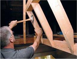
Different skylight, same installer. Here, he frames out the lightwell before cutting a hole in the ceiling because it was raining. First he headered off the ceiling joists, then the rafters around the roof opening, before angle cutting the studs between the two openings. (He cut the four corner studs first.)

image261

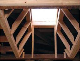
Подпись:The same lightwell after the roof has been opened: Note the doubled headers around all sides of the opening. Because all walls flare, this is a complicated piece of framing.

Skylight Framing

image262

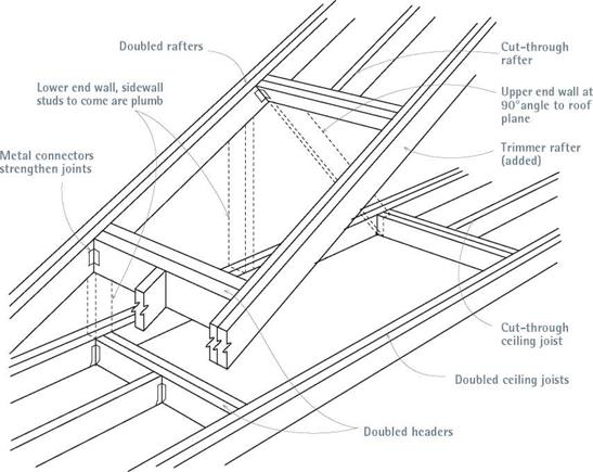
In addition to doubling headers at the ends of rough openings, double up rafters and joists running along the sides of openings. Framing out a lightwell will be somewhat easier if side walls and the lower end wall of the lightwell are plumb.

Velux units have integral curbs and proprietary flashing kits.

This one is "directional"—that is, with a top and bottom. Having slipped head flashing under shingles above, the installers will slip the unit’s head underneath. Small L-shaped brackets along the curb will mount to the sheathing.


image263

That done, the outside installer screws the bot­tom legs of the brackets to the sheathing.

Wrapping the curb with building paper or self­adhering membrane underlayment gives you an extra layer of protection before installing the unit’s apron, side flashing, and head flashing. Apply four 12-in.-wide strips of underlayment, one on each side, folding each so that it runs up onto the curb about 2 in. Apply the bottom piece first, which overlaps the shingles below; then place the side pieces and, finally, the top piece. If possible, slide the top piece of self-adhering membrane up under the building paper so you adhere it directly to the sheathing. Slit the folded strips where they overlap the curb corners so the strips lie flat, and apply a dab of roofing cement to adhere the slit pieces.

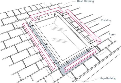
Install the apron flashing first, which runs along the lower edge of the skylight and overlaps the shingles below it. Holding the apron snug against the curb, attach it to the curb—not the roof—using a single screw (or nail) on each side. Although it’s usually not necessarily to caulk under the apron’s lower flange, follow the manu­facturer’s advice for your unit. Ideally, the apron will line up with a course of shingles, but in reno­vation that’s not always possible.

Install step-flashing along the sides, weaving the L-shaped flashing between the shingle courses. Ideally, shingle courses should stop 14 in. shy of the curb so that water can run freely along the sides. The vertical leg of each piece of step-flashing
should extend up high enough so it will be pro­tected from rain by curb caps; the horizontal leg should extend under the shingles at least 4 in. As with all flashing, avoid nailing in the channel where water will run. Rather, nail overlapping pieces of step-flashing to the curb only and high enough so the nails will also be protected by curb caps. If necessary, trim the last (uppermost) pieces of step-flashing so they don’t extend beyond the curb.

Install the head flashing by slipping its upper flange under the next full course of shingles above and pressing the head flashing snug to the curb. Attach the head flashing to the curb with one screw or nail at each corner. Then install a strip of building paper—or a second strip of self­adhering membrane—over the head flashing’s flange before shingling over it. Note: Stop the flashing strip and shingles 2h in. to 4 in. above the skylight curb, so there is a clear expanse of metal to clear leaves and accelerate runoff.

Installing cladding (curb caps) is the last step. These pieces cover and seal the tops of apron and side (step-) flashing and, on some models, the top of the head flashing as well. Follow your sky­light’s installation guide religiously. In some fixed models, the head flashing is the last piece to go on, covering the upper ends of the side cladding pieces. Details vary, but caps snap or screw on. Note: Better-quality units have self-sticking foam gaskets that are applied to the top of the curb before the caps are installed, which reduces air and dust infiltration.

Once the unit’s mounting brackets are screwed to the sheathing, wrap the curb with building paper or self­adhering membrane as described in the text. (Note: Because rain began falling during this photo session, the curb wasn’t wrapped until later.) Here, the apron’s bottom flange overlays the shingles below.

Подпись:image264
Working from the bottom up, apply L-shaped step flashing along the side. Each overlaps the one below and is nailed with a single nail to the side of the curb. The last pieces of step-flashing slide up under the head flashing. When all the step-flashing is placed, counterflashing strips fit down over them, sealing the unit.

image265

I Skylight Cladding

Cladding covers and seals the top legs of apron and step-flashing and—on some operable models—it covers the head flashing as well. Read installation instructions closely. Numbers on the cladding indicate the installation sequence.

Finish off with a couple more tasks. To reflect light, lightwells should be covered with drywall and painted a light color. Insulate around the lightwells to reduce heat loss and condensation. Because condensation is common around sky­
lights, cover the lightwell with water-resistant (WR) drywall, often called greenboard for its color. Stiffen the well’s outside corners with metal cornerbeads.

The Cretan cities and palaces: urban hydraulics brought to perfec­tion

Crete was inhabited by migration from Anatolia, probably at the end of the VIIth millen­nium BC. Its more highly developed civilization, the Minoan, dates from about 2100 BC. This maritime empire was apparently a peaceful one, since neither palaces nor cities were fortified – and this despite the threatening face of the monster that the legendary king Minos kept in his labyrinth according to the Greek legends of Theseus and Minotaur.[138] A creative and sophisticated urban and palatial architecture characterizes this civilization. The Egyptians know the Cretans as the Keftious, and Mesopotamians know them as the Kaptaras. The Cretans could not have been ignorant of the Eastern developments in urbanism and urban hydraulics, because at the same time northern Syria is experiencing the “belle epoch” of Mari (destroyed in 1761 BC), Elba (destroyed around 1600 BC, and Ugarit (destroyed about 1200 BC).

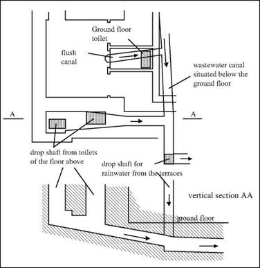
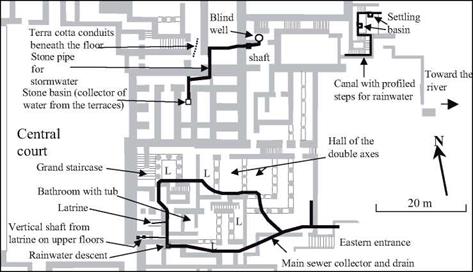
The remains of numerous cities have been found in Crete, as well as the remnants of four great “palaces” (or temples?): Knossos, Phaistos, Mallia, and Zakro. These cities and palaces have ample water supplies.[139] In the palace of Knossos, the largest in Crete, there are bathing rooms, latrines, and drains (Figure 4.4). These latrines have a “flush­ing” channel, dug into the floor, that is fed by an outside reservoir (Figure 4.3) and a sort of siphon, in an alcove of the back wall, connected to the drain. The bathing rooms have portable terra cotta bathtubs that can be arranged so that one can pour water over the bather from a separate room. Systems such as this, albeit of various degrees of sophist­ication, can be found in the other palaces on the island. For example, the guest quarters of Knossos include a room where voyagers can wash their feet in running water.

The Cretan cities and palaces: urban hydraulics brought to perfec­tion

Figure 4.2 Elements of a Minoan terra cotta pipeline (after Graham, 1987).

The Cretan cities and palaces: urban hydraulics brought to perfec­tion

Figure 4.3 Drainage of rainwater and wastewater, discovered in the east wing of the Knossos palace (Castleden, 1990). This area is at the lower left in Figure 4.4, which shows the overall layout of the eastern wing (see “latrine”).

But where does all this water come from? For Knossos, it is quite probably from a spring some 15 kilometers away. Terra cotta pipes following the natural slope of the land bring water first to the guest quarters, and then beyond to the palace. The pipeline cross­es a small river on a little bridge that provides access to the palace from the guest quar­ters.[140]

These Cretan aqueducts are, as far as we know, the first true water supply works. They were surely made of terra cotta conduits, and laid along the natural slope of the land, as were the later Greek aqueducts. And actual remains of terra cotta pipelines assembled from conical sections (Figure 4.2), that can fit into each other using flanged joints, have been found in Minoan palaces.[141]

Cretan urbanism is also remarkable for the way it uses rainfall runoff for sanitary purposes. In the palace of Knossos (Figure 4.4), Arthur Evans has identified laundries located at the eastern extremity of the palace. These laundries are apparently supplied by a pipe that descends along a stairway, bringing water from a basin where runoff from

The Cretan cities and palaces: urban hydraulics brought to perfec­tion

Figure 4.4 Hydraulic features identified in the eastern wing of the palace of Knossos. L = light well

the terraces is collected and stored.

In Knossos there are wastewater drainage systems, and the use of these same pipes for storm drainage further contributes to urban hygiene. Arthur Evans found two inde­pendent sewage networks in his excavations. One is made of terra cotta pipes, canals, and large collectors; the other uses smaller underground conduits. The system is serv­iced through manholes, and these manholes also capture rainfall runoff. Excavations directed by Nicolas Platon at Zakro have uncovered stone or terra cotta gutters under the floors, as well as masonry conduits covered with stone slabs. In the city of Palaikastro,[142] researchers have uncovered traces of stone gutters used to drain wastewater from hous­es, dumping the waste into the main sewer that flows under the central street. There is an analogous system of sewers in the Minoan city of Akrotiri on the island of Thera, buried around 1520 BC by the explosion of the volcano of Santorin.[143] Remnants of con­trol gates have been found at several of these sites.

The elaborate drainage systems of Crete mirror similar developments at other sites of the IVth and IIIrd millennia BC, such as Habuba Kebira and Mari on the Euphrates, Harapa and Mohenjo Daro on the Indus. It seems reasonable to suppose that the Minoan engineers were inspired by oriental concepts of drainage networks. It is, however, only in Crete that these networks are developed and generalized to the point that we have seen above. But as for the capturing and distribution of water for domestic supply, we are not aware of other examples in the orient prior to the Ist millennium BC. Therefore this was very likely a Cretan innovation.

Hydraulic works were also developed in support of agriculture. A canal network was constructed on the plateau of Lassithi, south of Mallia, for the drainage or irrigation of cultivated land. Recent detailed exploration of the region of Mallia, between 1989 and 1995, shows that the coastal plain was very actively cultivated in this period, in suf­ficient measure to feed the inhabitants of the 60 hectares of urbanized land around the palace. Gutters deliver water diverted from mountain streams to the fields through tem­porary storage in cisterns that are dug into the tops of hills.[144]

The Cretan cities and palaces: urban hydraulics brought to perfec­tion

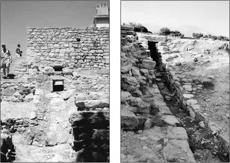
Figure 4.5. Outlets of the principal collectors of two Minoan palaces (photos by the author): – left, near the east entry of the Knossos palace; right, south of the Phaestos palace (under the large central court).

The Cretan palaces are destroyed several times by earthquakes, and then recon­structed. But the palaces, and the brilliant civilization of the island, come to an abrupt end about 1400 BC. The causes are not precisely known. It is possible that the explo­sion of the volcanic island of Thera (Santorin) caused an ecologic catastrophe when it covered part of the island with cinders, and that a tidal wave destroyed the island’s north­ern settlements. The bellicose Mycenaeans of continental Greece were also responsible for destruction of the palaces, symbols of the Minoan civilization. Only the Knossos palace survived for some time as the weakened seat of a power that seems now to have been Mycenaen.

These cataclysms, the explosion of Thera, the disappearance of Akrotiri, the abrupt end of Minoan commerce, are all probably the source of the legend of Atlantis, reported by Plato (427 – 347 BC) from Egyptian sources.[145] In any case, when he speaks of Atlantis, Plato gives tribute to the hydraulic developments of this legendary island, rec­ognizing both urban hydraulics and irrigation as shown in the following significant extract:

“I will now describe the plain, as it was fashioned by nature and by the labours of many gen­erations of kings through long ages. It was for the most part rectangular and oblong, and where falling out of the straight line followed the circular ditch. The depth, and width, and length of this ditch were incredible, and gave the impression that a work of such extent, in addition to so many others, could never have been artificial. Nevertheless I must say what I was told. It was excavated to the depth of a hundred, feet, and its breadth was a stadium every­where; it was carried round the whole of the plain, and was ten thousand stadia in length. It received the streams which came down from the mountains, and winding round the plain and meeting at the city, was there let off into the sea. Further inland, likewise, straight canals of a hundred feet in width were cut from it through the plain, and again let off into the ditch lead­ing to the sea: these canals were at intervals of a hundred stadia, and by them they brought down the wood from the mountains to the city, and conveyed the fruits of the earth in ships, cutting transverse passages from one canal into another, and to the city.”[146] [147]

Or again, this reference to the water supply:

“In the next place, they had fountains, one of cold and another of hot water, in gracious plen­ty flowing; and they were wonderfully adapted for use by reason of the pleasantness and excellence of their waters. Of the water which ran off they carried some to the grove of Poseidon (…) while the remainder was conveyed by aqueducts along the bridges to the outer circles (..)“

So here we may have direct tribute to the ancient know-how of the Minoans. But we must of course be careful to take these descriptions with a grain of salt, as they may just as easily reflect the ancient works of continental Greece.

Stage 4: Determining an Initial Content of Binder

The minimum content of binder in an SMA has been fixed at 6.0% (m/m), but a slightly higher quantity of binder in a mixture is advised. This is intended to provide protection from exceeding the lower production limit when producing the SMA.

To begin, an initial trial quantity of binder in mixtures should be adopted (the same for each of the three mixtures). The trial binder quantity should be adjusted depending on the density of the aggregate mixes. The reference density of an aggre­gate mix is typically 2.75 g/cm3; if the density differs, the quantity of binder should be adjusted in accordance with this rule: each change of density by 0.05 g/cm3 cor­responds to an adjustment of binder by 0.1% (m/m). For densities less than 2.75, and for densities greater than 2.75, the adjustments are positive ( + ) or negative (-), respectively.

A series of samples should be made up of 12 specimens of the SMA asphalt mix­ture, four for each SMA trial design gradation. Then nine of the 12 samples will be compacted according to the selected method (three for each SMA design), while the remaining three samples will be used to determine the maximum density according to AASHTO T209.

Samples can be compacted using either the Marshall method or the Superpave gyratory compactor. Compaction parameters are as follows:

• Marshall hammer: 50 blows on each side of a sample 100 mm in diameter

• Superpave gyratory compactor: 100 revolutions[34] on samples 150 mm in diameter

Due to the risk of excessive crushing, higher compaction efforts are not recom­mended. The temperature of compaction samples should be determined using AASHTO T 245, which specifies that the compaction temperature is that at which the binder viscosity equals 280 ± 30 cSt, or that provided by the manufacturer of a modified binder (when applicable).

Hydrologic Frequency Analysis

One of the basic questions in many hydrosystems infrastructural designs that an engineer must answer is, “What should be the capacity or size of a system?” The planning goal is not to eliminate all hydro-hazards but to reduce the fre­quency of their occurrences and thus the resulting damage. If such planning is to be correct, the probabilities of flooding must be evaluated correctly. The prob­lem is made more complex because in many cases the “input” is controlled by nature rather than by humans. For example, variations in the amount, timing, and spatial distribution of precipitation are the underlying reasons for the need for probabilistic approaches for many civil and environmental engineer­ing projects. Our understanding and ability to predict precipitation and its resulting effects such as runoff are far from perfect. How, then, can an engineer approach the problem of design when he or she cannot be certain of the hydro­logic load that will be placed on the infrastructure under consideration?

An approach that is used often is a statistical or probabilistic one. Such an approach does not require a complete understanding of the hydrologic phe­nomenon involved but examines the relationship between magnitude and fre­quency of occurrence in the hope of finding some statistical regularity between these variables. In effect, the past is extrapolated into the future. This as­sumes that whatever complex physical interactions control nature, the process does not change with time, and so the historical record can be used as a basis for estimating future events. In other words, the data are assumed to satisfy statistical stationarity by which the underlying distributional properties do not change with time, and the historical data series is representative of the storms and watershed conditions to be experienced in the future. An example that violates this statistical stationarity is the progressive urbanization within a watershed that could result in a tendency of increasing peak flow over time.

Подпись:
The hydrologic data most commonly analyzed in this way are rainfall and stream flow records. Frequency analysis was first used for the study of stream flow records by Herschel and Freeman during the period from 1880 to 1890

(Foster, 1935). The first comprehensive study was performed by Fuller (1914). Gumbel (1941, 1942) first applied a particular extreme-value probability distri­bution to flood flows, whereas Chow (1954) extended the work using this distri­bution. A significant contribution to the study of rainfall frequencies was made by Yarnell (1936). The study analyzed rainfall durations lasting from 5 minutes to 24 hours and determined their frequency of occurrence at different locations within the continental United States. A similar study was performed by the Miami Conservancy District of Ohio for durations extending from 1 to 6 days (Engineering Staff of Miami Conservancy District, 1937). An extremal probabil­ity distribution was applied to rainfall data at Chicago, Illinois, by Chow (1953), and more recent frequency analysis of rainfall data was performed by the U. S. National Weather Service (Hershfield, 1964; U. S. Weather Bureau, 1964; Miller et al., 1973; Frederick et al., 1977, Huff and Angel, 1989, 1992). Low stream flows and droughts also were studied statistically by Gumbel (1954, 1963), who applied an extremal distribution to model the occurrences of drought frequen­cies. In the United Kingdom, hydrologic frequency analysis usually follows the procedures described in the Flood Studies Report of 1975 (National Environ­ment Research Council, 1975). In general, frequency analysis is a useful ana­lytical tool for studying randomly occurring events and need not be limited to hydrologic studies. Frequency analysis also has been applied to water quality studies and to ocean wave studies.

Basic probability concepts and theories useful for frequency analysis are de­scribed in Chap. 2. In general, there is no physical rule that requires the use of a particular distribution in the frequency analysis of geophysical data. However, since the maximum or minimum values of geophysical events are usually of in­terest, extreme-value-related distributions have been found to be most useful.

Dry-Rodded Method

The dry-rodded method has been standardized in AASHTO T 19-00, where its thor­ough description has been included. It is recommended to perform two tests per sample and use the average value. The following gives a short outline of the equip­ment used and the modus operandi.

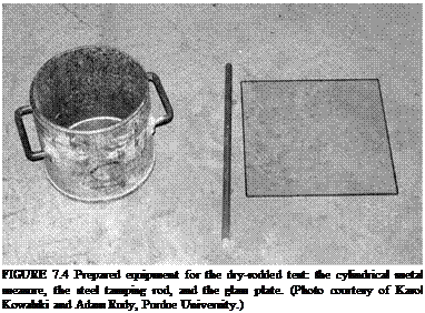
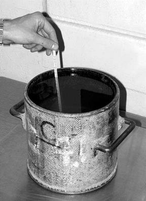
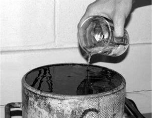
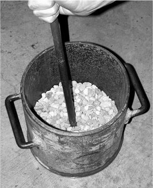
The equipment needed includes a balance, a steel tamping rod (rammer), a cylin­drical metal measure, a shovel, glass calibration plate (Figure 7.4), and grease or thick glycerin. The sample of aggregate is dried in an oven to a constant mass. The sample should be about 125-200% of an amount that fits in the container. The cylin­drical measure is calibrated by determining the volume using water and the glass plate (Figures 7.5 and 7.6); water-density corrective coefficients in relation to the temperature should be taken into account.

The test is performed as follows: [31] [32]

3.

Подпись: FIGURE 7.4 Prepared equipment for the dry-rodded test: the cylindrical metal measure, the steel tamping rod, and the glass plate. (Photo courtesy of Karol Kowalski and Adam Rudy, Purdue University.)

Having completed tamping the second layer of aggregate, fill the container with aggregate to overflowing and continue tamping down as previously described.

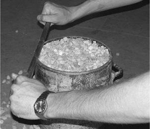
4. Even out the aggregate using your fingers or scrape away any excess aggre­gate with a rod so that protruding coarse particles will compensate for any gaps between them (Figure 7.8).

5. Determine the mass of the compacted aggregate by weighing the measure with aggregate and weighing it empty.

6. Calculations

• Calculate the bulk density of an aggregate according to the formula

G –

V

M = Bulk density of the coarse aggregate, kg/m3 G = Mass of a cylindrical measure and aggregate, kg T = Mass of a cylindrical measure, kg V = Volume of a cylindrical measure, m3 [33]

Dry-Rodded Method

Подпись:

(Gca-y w)-M
G – Y

ca w

-100% (v/v)

image61

FIGURE 7.5 Calibrating the measure—determining the water temperature. (Photo cour­tesy of Karol Kowalski and Adam Rudy, Purdue University.)


image62

FIGURE 7.6 Calibrating the measure—determining the measure volume. (Photo courtesy of Karol Kowalski and Adam Rudy, Purdue University.)


image63

FIGURE 7.7 Tamping down the first layer of a poured aggregate. (Photo courtesy of Karol Kowalski and Adam Rudy, Purdue University.)


image64

FIGURE 7.8 Clearing away the excess aggregate. (Photo courtesy of Karol Kowalski and Adam Rudy, Purdue University.)


M = Bulk density of a coarse aggregate in the dry-rodded condition, kg/m3 Gca = Bulk specific gravity (dry basis) of a coarse aggregate according to AASHTO T85 = GsbD

Yw = Density of water, kg/m3

STEP 4 MARK THE PLATES

Building walls is like baking a cake. Success depends on having all the right ingredients. When you mark the plates, you’re setting the exact locations for all of the headers, cripples, studs, corners, and wall intersections associated with each wall in the house.

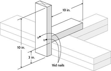
Подпись: їм їм їм їм їм и їм їм їм їм їм їм їм и їм їм їм їм їм їм їм и їм їм їм їм їм їм їм и їм їм їм їм їм їм и їм їм їм їм їм їм їм и їм їм їм їм їм їм їм и їм їм їм їм і MARKING CORNERS AND CHANNELS STEP 4 MARK THE PLATESSTEP 4 MARK THE PLATESПодпись: The fastest, most accurate way to mark corners and channels is with a tool the same width as the butt walls. In less than a minute, you can cut and nail together such a tool from scrap. Select two pieces of 2x stock about 10 in. long. Turn one piece on end and place the second piece flat against it to form a "T." With the second piece protruding over the first by 3 in., nail the two together with 16d nails.

Mark corners and channels first

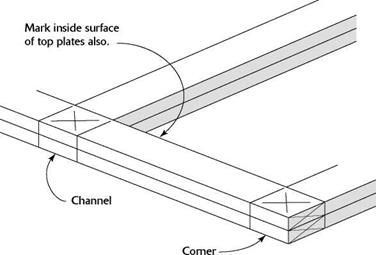
When marking up each plate, start with the loca­tions of corners and wall intersections, which are referred to as channels or tees (see the top illustra­tion at right). As we’ll see shortly, corners and channels require extra studs so that the walls can be properly nailed together once they are raised. The extra studs also provide backing for drywall on the inside and siding on the outside. Use a channel marker to mark corners and channels on the plates. Store-bought aluminum markers are available, as shown in the left photo on p. 90. It’s also easy to make your own (see the bottom illustration at right).

Take time to make accurate layout marks. Sloppy work at this stage means trouble after the walls have been raised and you begin to plumb and straighten them. Draw accurate lines along all edges of the marker, including the inside edges of the plates, where one wall inter­sects another. In other words, mark the inside, the outside, and the top surfaces of the through – wall plate. This is important. These corner and channel marks also indicate where the double top (or cap) plates will intersect, tying together through walls and butt walls. Use a keel to mark an “X” on the top plate to let the wall – builder know the location of a corner or chan­nel. Some carpenters write out the word “tee” to note the location of an intersecting channel.

Keep layout marks clean and simple

Methods of marking header locations on plates differ regionally. Whichever system you use, keep it simple. Check the floor plans for each header location, then position the header on the top plate, aligning the sides of the header with the edges of the plate. Mark down from both ends of the header, across both the top and the bottom plates. On outside walls, make these marks on the outside; on interior walls, make marks on the stud layout side.

Next to the end line, mark an “X” on both plates on the side away from the header to indi­cate the king-stud location (see the photo on p. 91). King studs are nailed alongside headers

Be sure to mark the inside, top, and outside of every through-wall plate with the locations of every intersecting wall, both channels and corners.

MAKING A CHANNEL MARKER

Mark joining walls with a channel marker. Be sure to make layout marks on all three exposed faces of the plates on the inside, the outside, and the top.


An “X” is easy to spot. Mark an “X” or the word “tee” on the top plate to indicate where one wall intersects another.


STEP 4 MARK THE PLATES