What’s in My Walls?

The first step to determining your upgrade options is to learn the type and amount of insulation, if any, in your walls. Houses built before 1930 often were left uninsulated, so you will find either empty stud bays or insu­lation that was added later. Houses built in the ’40s, ’50s, and beyond typically were in­sulated, but often with thin batts that didn’t fill the wall cavity.

The possibilities shown here represent the most common types of early insulation, but it’s not a comprehensive list. Many of the earliest forms of insulation were driven by the local industry. If the town was home to sawmills, the surrounding houses could be insulated with sawdust. If the town was an agricultural hub, rice hulls were fairly com­mon. What you find in your walls is limited only by the whim of the builder and the pre­vious homeowners.

Fiberglass


Rock wool


Cotton batts


What’s in My Walls?

What’s in My Walls?What’s in My Walls?What’s in My Walls?

BALSAM WOOL, 1940s

What is it? "Wool" is a bit misleading because this insulation is essentially chopped balsam wood fibers.

Positive ID Although some installations may have been loose fill, this tan/brown insula­tion was most often packaged and in­stalled in black-paper-faced batts. The tan fibers look similar to sawdust.

Health note Balsam wool is not a health hazard, but take care when investigating this insulation; wear a dust mask. Because the paper batts are likely to be brittle to the touch, disturbing them too much may leave holes that will decrease thermal performance.

Upgrade outlook This insulation was typi­cally fastened to wall studs similar to fiber­glass batts. Balsam wool should still yield an R-value of between R-2 and R-3 per in. if installed correctly, but the batts are likely only a couple of inches thick. Consider fill­ing the remaining empty space in the stud cavities with blown cellulose or fiberglass. Some manufacturers of pour foam also recommend their product for this type of installation.

UREA-FORMALDEHYDE FOAM, 1950 TO 1982 (MOSTLY IN THE LATE 1970s)

What is it? Also known as UFFI, this once – popular retrofit option is a mixture of urea, formaldehyde, and a foaming agent that were combined on site and sprayed into wall cavities.

Positive ID Lightweight with brown­ish-gold coloring, this foam is fragile у and likely to crumble if touched (hence the smooth chunks shown at left).

Health note Because this open-cell foam was banned in 1982 and most of the off-gassing happened in the hours and days following installation, chances of elevated levels of formaldehyde are slim.

Upgrade outlook Although it’s rated at R-4.5 per in., UFFI rarely performs at this level. This foam is well known for its high rate of shrinkage and tendency to deteriorate if in contact with water, and it also crumbles if disturbed during remodeling. The result is walls that likely have large voids, but this insulation isn’t a good candidate for discreet removal. The best option here is to add rigid foam to the exterior to help to make up for the large air voids that are likely hidden in the wall.

VERMICULITE, 1925 TO 1950

What is it? This naturally occurring mineral was heated to make it expand into a lightweight, fire-retardant insulating material.

Positive ID

Brownish-pink or brownish-silver in color, these lightweight pellets were typically poured into closed wall cavities and into the voids in masonry blocks.

Health note Seventy to eighty percent of vermiculite came from a mine in Libby, Mont., that was later found to contain asbes­tos. The mine has been closed since 1990, but the EPA suggests treating previously in­stalled vermiculite as if it is contaminated. If undisturbed, it’s not a health risk, but if you want to upgrade to a different type of insula­tion, call an asbestos-removal professional.

Upgrade outlook Vermiculite doesn’t typi­cally settle and should still offer its original R-value of between R-2 and R-2.5 per in. This low thermal performance makes it an attractive candidate for upgrade, especially because it’s a cinch to remove: Cut a hole, and it pours right out. But the potential for asbestos contamination makes the prep work and personal protection more of a hassle, and the job more costly as a result.

Подпись:What’s in My Walls?If cavities are not filled to the top, consider topping them off; fiberglass, cellulose, or pour foam will work if there is access from the attic.

FIBERGLASS, LATE 1930s TO PRESENT

What is it? This man­made product con­sists of fine strands of glass grouped together in a thick blanket.

Positive ID Most often yellow, though pink, white, blue, and green types are used. Older products were typically paper-faced batts.

Health note Official health information on fiberglass is ambiguous; the argument over whether it’s a carcinogen continues. Even if it’s not a cancer-causing material, it will make you itchy and irritate your lungs if disturbed. Be on the safe side if you plan to remove this insulation; wear gloves, long sleeves, goggles, and a respirator.

Upgrade outlook Fiberglass has a decent thermal performance of between R-3 and R-4.5 per in., but early products were typically only about 2 in. thick. Consider filling the remaining empty space in the stud cavities with blown cellulose or blown fiberglass. Some manufacturers of pour foam also recommend their product for this type of installation.

ROCK WOOL (MOSTLY IN THE 1950s)

What is it? Rock wool is a specific type of mineral wool, a by-product of the ore – smelting process.

Positive ID This fluffy, cottonlike material was typically installed as loose fill or batts.

It usually started out white or gray, but even the white version will likely be blackened or brown from decades of filtering dirt out of air flowing through the cavity.

Health note Research indicates that this is a safe material. It’s still in use today, and it’s gaining popularity among green builders.
What’s in My Walls?Подпись:What’s in My Walls?Upgrade outlook Rock wool is fairly dense, so it’s less likely than other materials to have settled over time. If installed correctly, it should still yield a value of R-3 to R-4 per in., about the same as blown fiberglass or cellulose insulation. If anything, consider adding housewrap or a thin layer of rigid foam to the outside of the wall to air-seal the structure. If more insulation is desired, go with rigid foam.

Подпись: Out with the Old If your walls are filled with old insulation and your remodeling plans don't involve gutting the house, then you can either add rigid insulation to the exterior of the house (see the sidebar on the facing page) or, in some cases, surgically remove the old insulation. Vermiculite can be removed by drilling a hole through the wall at the bottom of the stud cavity and letting gravity empty the stud bays. In balloon-framed houses, which have wall studs that run continuously from the foundation to the roofline, blocking in the basement can be removed to access the stud cavities above. Batts or dense fibrous insulations can be removed by cutting a “bellyband,” in which a narrow strip of wall is removed about 4 ft. from the floor (this can be done from the exterior as well). With this strip of wall open, the batts can be pulled out—a homemade hook helps—and new insulation can be blown or poured into the cavities through the same openings before they are patched. What’s in My Walls?What’s in My Walls?What’s in My Walls?COTTON BATTS, 1935 TO 1950

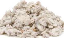
What is it? Made of a naturally grown material, cotton batts are treated to be flame resistant.

Positive ID This white insulation is dense, but still fluffy.

It’s not as refined as cotton balls; instead, it’s likely to have more of a pilly, fuzzy appearance.

Although several companies manufactured cotton batts, one of the most popular seems to have been Lockport Cotton Batting. Look for a product name (Lo-K) and company logo on the batts’ paper facing.

Health note Cotton is all natural and is perfectly safe to touch, but don’t remove the batts or otherwise disturb the insulation without wearing at least a nuisance dust mask or respirator to protect your lungs. Also, cotton by nature is absorbent, so if it gets wet, it will take time to dry.

What’s in My Walls?Upgrade outlook The growing popular­ity of green-building materials has sparked renewed interest in cotton batts. Although these modern versions of cotton batting, often referred to as "blue-jean insulation," have an R-value of R-3.5 to R-4 per in., there is some controversy over the R-value of the old versions. Some sources claim the old products perform similarly to the modern versions, and others estimate the R-value to be as low as R-0.5 per in. Considering the density of the old cotton batts, such a low R-value seems unlikely.

What’s in My Walls?

Justin Fink is a senior editor of Fine Homebuilding.

What’s in My Walls?

Подпись: POLYISOCYANURATE (POLYISO) This is the most expensive type of rigid foam (about 80Ф per sq. ft. for 1-in. thickness), but also the best insulator (about R-6.5). Polyiso is a popular choice for retrofit applications because it packs more insulation into a thin package—less hassle for detailing windows and doors. All polyiso boards are faced, most with foil, which retards the flow of water vapor.

Rigid Foam Always Works

It doesn’t matter how the walls were built, what type of insulation they have now, or how many obstructions are hidden in the wall cavities: Rigid – foam panels installed over the exterior side of the walls are always an option. However, installation is not as easy as cutting the lightweight panels with a utility knife and nailing them to the framing, though that’s part of it.

Rigid foam must be applied directly to the fram­ing or sheathing, or on top of the existing siding, then covered with new siding. In any case, you are faced with a full re-siding job and maybe a siding tearoff. Also, depending on the added thickness of the panels, windows and doors might need to be furred out, and roof rakes and eaves extended. As long as the installation is detailed carefully, though, the result is wall cavities that stay warm and dry, allowing your existing insulation to per­form its best.

Panels are available in 2-ft. by 8-ft. or 4-ft. by 8-ft. sheets, and range from У2 in. to 2 in. in thickness. Vapor permeability is determined by the type of foam and the presence of a facing. Panels faced with foil or plastic are class-I vapor retard­ers (also called vapor barriers) and should not be used if the house has poly sheeting or an equiva­lent vapor retarder under the drywall. Unfaced or fiberglass-faced panels allow water vapor to pass and won’t be problematic in combination with a class-1 retarder.

EPS is unfaced, which makes it more fragile to handle but also allows the passage of water vapor. Unfaced EPS should be installed in combination with #15 felt paper or housewrap.

EXTRUDED POLYSTYRENE (XPS)

XPS falls in the middle of the three types of rigid-foam insulation in terms of cost and performance. Easy to spot by its blue, pink, or green color, XPS is slightly more expensive than EPS (50Ф per sq. ft. for 1-in. thickness) and also offers better performance (about R-5 per in.). Panels are commonly unfaced, and though water-vapor transmission slows on thicker panels, all XPS panels greater than 1 in. thick are considered class-ll vapor retarders, which allow water vapor to pass.

What’s in My Walls?

EXPANDED POLYSTYRENE (EPS)

These white, closed-cell panels are made from the same polystyrene beads used in disposable coffee cups. EPS is the least expensive option (45Ф per sq. ft. for 1-in. thick­ness) and has the lowest R-value of the group (about R-4 per in.). Some

SOURCES

www. owenscorning. com

www. polarcentral. com

www. styrofoam. com

What’s in My Walls?

What’s in My Walls?Pour Foam Is the Most Thorough

T

his water – or HFC – (hydrofluorocarbon) blown mixture is injected into the wall cavity from either the interior or the exterior through two or more 3/4-in.- to l-in.-dia. holes. The foam flows to the bottom of the stud cavity, where it slowly expands upward, surrounding even the most complicated plumbing and electrical obstructions, and filling every gap to create an airtight wall assembly.

Pour foam follows the path of least resistance as it expands, so the bottoms of stud cavities (in the basement or crawlspace) need to be sealed in balloon-framed houses. Old houses with siding installed directly over the studs will likely have foam squeeze-out between siding courses, which must be removed with a paint scraper once cured.

Blowouts or distortions in drywall, plaster, or sid­ing are also possible, although this is typically not a concern if the foam is installed by trained profes­sionals. Still, this is the reason why most pour-foam companies don’t sell directly to the public, instead relying on a network of trained installers. Tiger Foam®, on the other hand, sells disposable do-it – yourself kits to homeowners.

Rigid foam

What’s in My Walls?

Although there are videos on the Internet showing pour foam being injected into wall cavities that have fiberglass insulation-compressing the batts against the wallboard or sheathing-most manufacturers do not recommend this practice. The pour foam could bond to individual strands of fiberglass and tear it apart as it expands, creating voids. Tiger Foam is the exception, but the company recommends the use of a long fill tube to control the injection.

Installation from the exterior requires removal of some clapboards or shingles. Installation from the inside is easier, but requires more prep work (moving furniture, wall art, drapes, etc.). Homeowners can expect a slight odor after installation and for the day following; proper ventilation is a must.

Homeowners can plan to spend from $2 to $6 per sq. ft. of wall area for a professional installation, depending on job specifics and foam choice. Tiger Foam’s do-it-yourself kits sell for about $4 to $7 per sq. ft., depending on quantity. Open-cell foams-which are more permeable to water-vapor transmission-are about R-4 per in.; closed-cell, around R-6 per in.

SOURCES

www. demilecusa. com

www. fomo. com

www. icynene. com

www. polymaster. com

www. tigerfoam. com

What’s in My Walls?
The Most Common Approach

his method begins with compressed packs of dry cellulose or fiberglass, which are dumped into the hopper of a blowing machine, where they are agitated and loosened. A 1-in.- to 2-in.-dia. hose runs from the blowing machine through a hole in the inte­rior or exterior side of the wall and is lowered to the bottom of the stud cavity. The installation process usually involves either one hole at the top of each cavity and a long fill tube that is withdrawn as the insulation fills the space, or a “double-blow” method, where two holes are used-one about 4 ft. from the floor and a second near the top of the wall.

Both cellulose and fiberglass do a good job of surrounding typical plumbing and electrical utilities routed through the wall, but the finished density of the insulation is crucial. Cellulose that’s installed too loosely will settle and create voids in the wall, and fiberglass that’s packed too densely will not offer the performance you paid for.

What’s in My Walls?

Cellulose

This insulation is made from 80% post-consumer recycled newspaper and is treated with nontoxic borates to resist fire and mold. It’s a good choice because of its balance among cost, thermal perfor­mance, and environmentally friendly characteristics. Also, unlike fiberglass insulation, cellulose doesn’t rely only on its ability to trap air to stop heat flow. Cellulose can be packed tightly into a wall cavity to resist airflow-a practice called “dense-packing”- yielding an R-value of R-3 to R-4 per in.

Although blowing loose-fill cellulose into attics is a pretty straightforward process (and is touted as a good do-it-yourself project), dense-packing is more complicated. As the material is blown into the cavity, the blowing machine bogs down, letting the installer know to pull back the hose a bit. This process repeats until the wall is packed full of cel­lulose. Although it is possible to pack cellulose too densely, the more common problem is not packing it densely enough. Most blowing machines that are available as rentals are designed for blowing loose cellulose in an open attic. These machines aren’t powerful enough to pack cellulose into a wall cavity, and unpacked cellulose can settle and leave voids. The Cellulose Insulation Manufacturers Association (www. cellulose. org) recommends that dense-pack cellulose be installed only by trained profession­als with more powerful blowing machines. Material prices are about 25Ф per sq. ft. of wall space.

Finally, if soaked with water, cellulose is likely to settle, leaving voids. Then again, if there’s liquid water in the wall cavity, voids in the insulation will be the least of your worries, and the least of your expenses.

What’s in My Walls?

What’s in My Walls?Fiberglass

What’s in My Walls?

Fiberglass

This loose-fill insulation is made from molten glass that is spun into loose fibers. The material is avail­able in two forms, either as a by-product of manu­facturing traditional fiberglass batts and rolls, or from “prime” fibers produced especially for blowing applications. In either case, the material is noncom­bustible, will not absorb water, and is inorganic, so it will not support mold growth.

Fiberglass resists heat flow by trapping pockets of air between fibers, so the insulation must be left fluffy to take advantage of the air-trapping nature of the material. The R-value (typically between R-2.5 and R-4) is dependent not only on the thickness of the wall cavity but also on the density at which the insulation is installed. For information on ensuring that the fiberglass is installed to provide the stated R-value, visit the North American Insulation Manu­facturer’s Association (www. naima. org) for a free overview.

Because fiberglass doesn’t need to be blown to such high densities, it’s a more user-friendly installa­tion for nonprofessionals. On the other hand, loose fiberglass is not as readily available as cellulose, which is often a stock item at home-improvement centers. Finally, fiberglass advocates contend that their product won’t absorb water and that cellulose will—^though fiberglass will still sag if it becomes wet. Material prices are about 45Ф per sq. ft. of wall space.

SOURCES

www. certainteed. com

www. greenfiber. com

www. johnsmanvllle. com

www. knaufusa. com

www. owenscorning. com

Подпись: IS>

HEADERS

Every opening in a wall must have a header over it. Headers must be able to carry a cumulative load and transfer it downward without warping, flexing, or pulling away from the sides of the opening. Thus headers must be sized according to the loads they carry and the distances they span. Your local building code will have the final say in sizing them.

That noted, many builders in North America use this rule of thumb when sizing headers for single-story buildings with 2×4 walls and a 30-lb. live load on the roof: The nominal depth a 4 x header in inches equals the span in feet of the opening. For example, if a builder uses No. 1 grade Douglas fir on edge, its spans look like this:

Douglas Fir Header Spans

HEADER SIZE (in.)

SPAN (ft.)

4×4

4

4×6

6

4×8

8

4×10

10

4×12

12

Oversizing headers. Span tables establish mini­mum requirements. In the field, however, experi­enced builders routinely oversize headers—using 4x12s to span all openings, interior and exterior. This is a considerable overkill, say, for a 4-ft.-wide window. But it has important advantages:

► Same-size headers ensure that the tops of most exterior openings will be at the same height, which is aesthetically pleasant.

► The additional cost of using an oversize beam is more than offset by the peace of mind it brings. That is, there won’t be any cracks in finish surfaces caused by undersize beams.

► The reasons for using a 4×10 or 4×12 for a partition are equally compelling. Should a nonbearing partition become point-loaded
because of structural shifts, its header should bear the additional load easily.

► Even in nonbearing walls, the header is the weakest point, structurally. Each time you shut a door, you compress the air in the room causing the wall to flex. The more solid wood you’ve got to nail to, the stronger the con­nection. (Code requires at least five 16d nails through-nailed into each end of a header.)

► But the most compelling reason is time. Cutting an oversize header from solid stock is far quicker than cutting and laminating two pieces of 2x lumber to a i^-in.-thick plywood core. (The 12-in. core makes the whole package exactly 312 in. thick, the width of a nominal 2×4.) You also save time because you don’t need to cut dragon’s teeth, the term pros use for cripple studs between a header and the top plate.

ASSEMBLING THE WALL

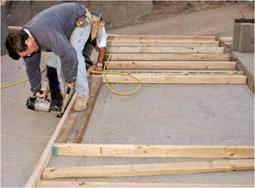
After marking the top and bottom plates, and cutting full-length studs, start assembling the wall. Place the plates on edge, roughly a wall height apart. Then insert the studs on edge between them. Again, use straight studs at wall ends and cabinet locations; elsewhere, place slightly bowed studs crown (bow) up so that stud ends will rest on the deck when it’s time to nail them to the wall plates.

Nailing studs. Position studs to the squared marks along the plates. Then end-nail studs through the sole plate, using two 16d common nails at each end. Space nails h in. to 1 in. from the edge of the plate. If you stand on the stud as you nail it, it will stay put. As you nail, be sure that stud and plate edges are flush, or the result­ant wall plane won’t be flat. When you’ve nailed all studs to the sole plate, nail the top plate. Important: If the sole plate will sit on concrete, it should be pressure-treated lumber or a naturally rot-resistant wood such as redwood. Moreover, all nails set into redwood or pressure-treated

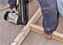
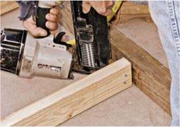
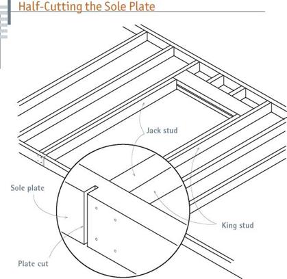
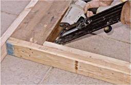
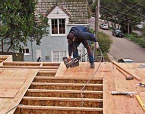
Подпись: When nailing the top plate to studs, lift the studs as needed so their edges align with the top plate's. Flush studs and plates allow drywall finishing to go smoothly. This exterior wall will have a doubled top plate; the second plate is nailed on once the wall is up, tying this wall to another.image331Подпись: Because a 3x4 mudsill is too thick to end-nail through, toenail studs instead. Here, pneumatic nailers really shine: They nail so quickly that studs won't drift off stud marks, as they frequently do when you're hand-nailing them.image332image333Подпись: A stud wall a with continuous sole plate is less likely to flop around as you raise it, but it's difficult to cut through a plate once it's resting on a subfloor. The solution? Cut halfway through the sole plate before you nail it to studs, and finish the cuts after the wall is up.

Подпись: After using five 16d nails to end-nail the header through the king stud, face-nail the trimmer stud to the king.
image334

plates must be galvanized so they won’t be cor­roded by chemicals in the wood.

Framing the rough opening. After cutting the header, end-nail the king studs (through the plates), on both sides of the RO. If you’re installing a full-height header such as a 4×12, insert the header between the king studs and nail down through the top plate into the header, to draw it tight to the plate. Then nail through the king studs into the ends of the header, using at least five nails per end. Next, to determine the length of the jack studs, measure from the under­side of the header to the top of the sole plate. Cut the jack studs slightly long; tap them into place; and face-nail them to the king studs, making sure their edges are flush.

If the header requires cripple studs between it and the top plate, install king studs, then jack studs, then the header. Holding the header tight to the top of the jack studs, nail through the king studs into header ends. If the header is laminated from pieces of 2x lumber, each piece should get two or three nails per end. Then cut and toenail the cripple studs that run between the top of the header and the top plate. If you’re framing a rough opening for a door, you’re done.

However, if you’re framing a rough opening for a window, your final steps will be leveling and toenailing the sills (also called saddles) to jack studs and then nailing cripple studs between the sills and the sole plate. Again, space cripples according to the 16-in. on-center markings along the plates.

Leaving the sole uncut. You’re now ready to tilt up the assembled wall. Note, however, that sole plates haven’t yet been cut and removed within door ROs, and for good reason: It’s far easier to raise a wall if its sole plate is continuous. Thus cut only halfway through the sole plate while it’s flat on the deck, as shown in "Half-Cutting the Sole Plate.” Finish the cut once the wall is up and nailed down.

Exploring Your Options

To assess the framing hidden behind finish surfaces, go where it’s exposed: the basement and the attic. Joists often run in the same direction from floor to floor.

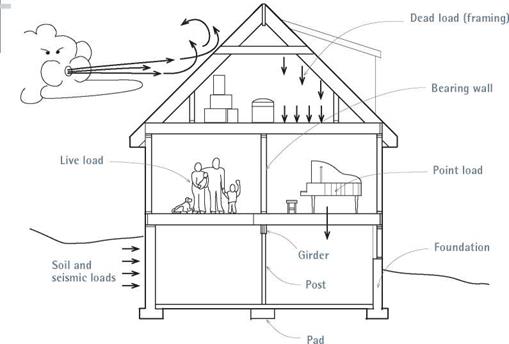
Generally, a girder (also called a carrying timber or beam) runs the length of the house, with joists perpendicular to it. Some houses will have framed cripple walls (short walls from the top of a foundation to the bottom of the first-floor joists) instead of a girder. Main bearing walls often run directly above the girder, but any wall that runs parallel to and within 5 ft. of a girder or cripple wall is probably bearing weight and should be treated accordingly.

Bearing walls down the middle of the house are also likely to be supporting pairs of joists for the floors above. That is, most joists are not continuous from exterior wall to exterior wall—they end over bearing walls and are nailed to companion joists coming from the opposite direction. This allows the builder to use smaller lumber—

2x6s rather than 2x8s, for example—to run a shorter span. If you cut into such a bearing wall without adding a header, the joists above will sag.

Large openings in obvious bearing walls are often spanned by a large beam or a header that supports the joists above. These beams, in turn, are supported at each end by posts within the wall that carry the load on down to the foundation. These point loads must be supported at all times. Similarly, large openings in floors (stair­wells, for example) should be framed by doubled headers and trimmers that can bear concentrated loads.

Подпись: are always surprises once you start. If you plan to remove walls, be sure to hire a structural engineer to review your plans. Framing Walls The framing of walls is arguably the most common carpentry task in renovation, and it employs many of the layout and assembly techniques you'd use elsewhere to construct walls, floors, and roofs. For a deeper look at carpentry, consult Rob Thallon's Graphic Guide to Frame Construction or Mike Guertin and Rick Arnold's Precision Framing, both published by The Taunton Press. Basically, wood-frame walls are an array of vertical studs nailed to horizontal top plates and sole (bottom) plates. Depending on whether walls are bearing or nonbearing, plates may be doubled. Although 2x4 walls are more common and less expensive, 2x6 walls allow you to install thicker insulation and route pipes more easily. To simplify matters, the examples in this section assume 2x4 framing. HANDLING LUMBER Here are a few lumber-handling tips that'll save energy and make the job go quicker. Minimize moves. Lumber is heavy. Tell your lumberyard to load the delivery truck so that the lumber you'll use first—say, floor joists—will be on the top of the load. Clear a level place close to the work site where the truck can unload. Many suppliers have boom trucks that can unload lumber stacks directly onto a work deck. Sort your lumber. Lumber today is often bowed, so eyeball each piece for straightness—and sort it into like piles. Save the straight stock for kitchen and bathroom walls—especially those that will get cabinets or be tiled—and for corners, top wall plates, and jack studs along rough openings (ROs). Pieces with slight bows (J4 in. in 8 ft.) can be used as studs and joists, but draw an arrow on the face of the lumber to indicate which way the lumber bows so you remember to place slightly bowed joists crown (bow) up, so they'll be less likely to sag when loaded. Set aside stock that bows more than '/ in. in 8 ft., which you'll cut shorter and use as headers, cripple studs, and blocking. Return corkscrew (twisted) studs to the lumberyard for credit. Be methodical. Snap chalklines onto floors to mark wall plates. Cut top and bottom plates. Then mark stud locations and ROs onto the plates. Make a cutting list: By cutting same- length lumber all at once you'll save a ton of time. If possible, cut lumber or plywood right atop the stack that the lumberyard truck delivered. Finally, it may be wise to leave a wall where it is if pipes, electrical cables, and heating ducts run through it. Look for them as they emerge in unfinished basements or attics. (^) Electrical wiring is easy enough to remove and reroute—but disconnect the power first! However, finding a new home for a 3-in. or 4-in. soil stack or a 4-in. by 12-in. heating duct may be more trouble than it’s worth.
Подпись: t AIПодпись: Precut studs save labor and time; they're available in several lengths. Buy 92У,-ІП. studs if finished ceiling heights are 8 ft. (92У4 in. + 3 in. for two wall plates = 95V4 in.), 88-in. studs if the ceilings are 7 ft. 6 in., and 104-in. studs if the ceilings are to be 9 ft.Подпись: 1111

NAILING IT

On larger renovations these days, pneumatic nailers do most of the work, but it’s worth know­ing how to use a hammer correctly. Then you’ll create fewer bent nails, splits, and dings (dented wood when the hammer misses the nail), and perhaps avoid a smashed thumb, tendonitis, and joint pain.

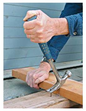
The perfect swing. If you’re driving large nails such as 16d commons, start the nail with a tap. Then, with a relaxed but firm grip on the end of the hammer handle, raise the hammer head high and swing smoothly from your shoulder. If you’re assembling stud-wall elements, spread them out on a deck, put one foot on the lumber to keep it in place, bend forward slightly, and let the falling hammer head’s weight do some of the work. Just before striking the nail, snap your wrist slightly to accelerate the swing.

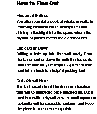
However, if you’re driving smaller nails (6d or 8d), you won’t need as much force to sink them. So choke up on the handle and swing from the elbow. Choking up is particularly appropriate if you’re driving finish nails because you’ll need less force and be less likely to miss the nail and mar the casing. It’s also necessary to choke up when there’s not enough room to swing a hammer freely or where you must drive a nail one-handed in a spot that you need to stretch to reach.

Work SAFELY

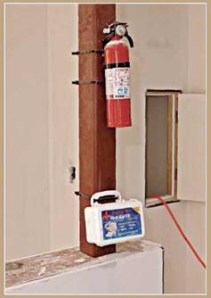
Put first-aid kits and fire extinguishers in a central location where you can find them quickly. Likewise, gather hard hats, safety glasses, hearing protection, and respirator masks at the end of each workday so they’ll be on hand at the start of the next.

image318

I Loads and Structure

image319

Подпись:Подпись:image320Plywooc

To nail plywood panels 1k in. thick or less, most codes specify 6d common nails spaced every 6 in. along the panel edges and every 12 in. in the field. Panels thicker than % in. require 8d common nails spaced in the same pattern. (Structural shear walls are typically nailed with 10d nails 4 in. to 6 in. on center along the edges and 12 in. on center in the field, but an engineer should do an exact calculation.)

Don’t overdrive nails. Ideally, nail heads should depress but not crush the face ply of the plywood. Panel strength isn’t affected if nail heads are overdriven by %6 in. or less, but if more than 20 percent of the nail heads are % in. or deeper, the American Plywood Association recommends adding one extra nail for each two overdriven ones.

Dnanm<>fif<.iiailav nmr. i______________________________________________________________________________ i

sure that’s too high is the most common cause of overdriven nails. It’s far better to set the nailer pres­sure so the heads are flush, and then use a single hammer blow to sink each nail just a little deeper.

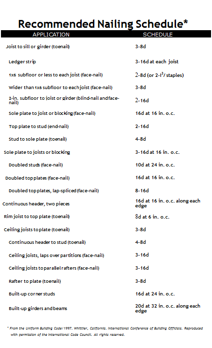
Подпись: The right nail. The nailing schedule given in "Recommended Nailing Schedule,” on the facing page, suggests the size and number of nails you need for various framing tasks, but local building codes will have the final say. When joining two pieces of framing lumber, nails should be long enough to penetrate the second piece of wood, without sticking out its other side. Properly sized nails are also less likely to split board ends. As the table indicates, use two 16d nails to end-nail a stud through a plate, and four 8d nails, which are shorter and skinnier than 16d nails, to toenail stud ends to sole plates. Speaking of splits, you can reduce them by first hammering nail points to blunt them. Removing nails. Everybody inadvertently bends nails now and then, especially when nailing at an odd angle or in a tight space or nailing into a hard wood like southern pine. To remove a bent nail, slip a block under a claw hammer head to increase the leverage as you pull out the nail; if the nail head is buried too deep to grasp with a claw hammer, use a cat's paw, which has pointed claws, to dig it out. LAYING OUT WALLS Wall layout varies, depending on whether you're erecting walls in open space (say, framing an addition) or within existing space (adding a parti- NAILING TIPS

image322

A wood block under your hammer head makes nail-pulling easier.


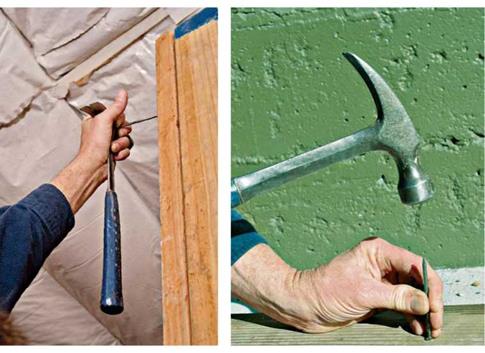
To nail where it’s hard to reach, start the nail by holding it against the side of the hammer and smacking it into the wood. Once the nail is started, you can finish hammering with one hand.


A blunted nail point is less likely to split wood because it will crush the wood fiber in its path rather than wedging it apart, as a sharp nail point does.


image321

Подпись: Assembling a wall on the ground is no guarantee that lumber edges will line up. Here, a builder uses his hammer to raise the top plate flush to the header, before nailing. Wear safety glasses when using a pneumatic nailer.image323Подпись: Recommended Nailing Schedule* APPLICATION SCHEDULE Joist to sill or girder (toenail) 3-8d Ledger strip 3-16d at each joist 1x6 subfloor or less to each joist (face-nail) 2-8d (or 2-І3/ staples) Wider than 1x6 subfloor to each joist (face-nail) 3-8d 2-in. subfloor to joist or girder (blind-nail and face-nail) 2-16d Sole plate to joist or blocking (face-nail) 16d at 16 in. o.c. Top plate to stud (end-nail) 2-16d Stud to sole plate (toenail) 4-8d Sole plate to joists or blocking 3-16d at 16 in. o.c. Doubled studs (face-nail) 10d at 24 in. o.c. Doubled top plates (face-nail) 16d at 16 in. o.c. Doubled top plates, lap-spliced (face-nail) 8-16d Continuous header, two pieces 16d at 16 in. o.c. along each edge Rim joist to top plate (toenail) 8d at 6 in. o.c. Ceiling joists to plate (toenail) 3-8d Continuous header to stud (toenail) 4-8d Ceiling joists, laps over partitions (face-nail) 3-16d Ceiling joists to parallel rafters (face-nail) 3-16d Rafter to plate (toenail) 3-8d Built-up corner studs 16d at 24 in. o.c. Built-up girders and beams 20d at 32 in. o.c. along each edge * From the Uniform Building Code/1997. Whittier, California. International Conference of Building Officials. Reproduced with permission of the International Code Council. All rights reserved.

tion). In both cases, use house plans to position walls. Snap chalklines onto subfloors (or floors) to indicate wall sole plates. If you’re building a wall within a room, next measure from existing framing to determine the height and length of the new wall, as described in "Reinforcing and Repairing the Structure,” on p. 165. Finally, mark the locations of ROs, wall backers (blocking you nail drywall corners to), and studs into plates.

The easiest way to frame a wall is to construct it on a flat surface and tilt it up into place. Once the wall is lifted, just align its sole plate to a chalkline on the floor sheathing. This construc­tion method is also stronger, because you can end-nail the studs to the plates rather than toe – nailing them. Sometimes, there’s not enough room to tilt up walls, a situation which is addressed later in this chapter.

I Stud-Wall Elements

image324

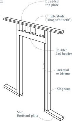
If you use doubled 2x6s for your header in a rough opening in standard 8-ft. wall framing, you need cripple studs to support the doubled top plate. If you use a 4×12 instead, it will support the top plates. Although code may allow a single top plate for nonbearing walls, a single plate offers little to nail drywall to, if the ceiling is finished before the wall.

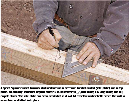
Подпись: A Speed Square is used to mark stud locations on a pressure-treated mudsill (sole plate) and a top plate. An Xusually indicates regular studs 16 in. on center; a _/,jack studs; a K king studs; and a C, cripple studs. The sole plate has been predrilled so it will fit over the anchor bolts when the wall is assembled and lifted into place. I Stud Layouts________

STUD-AND-PLATE LAYOUT

Подпись: Marked stud edges

Mark stud edges on plates so that stud centers will be spaced 16 in. on center (O. C.).

Distances (O. C.)

48 in.

16 in.

16 in.

16 in.

X

X

<

X

X

<

151/4 in.

in.

31 1/4

47’/4 in.

Подпись: PROnP When partitions run perpendicular to the joists, center the studs over the joists whenever possible. Aligning studs and joists creates straight, open channels from floor to floor, so plumbers and electricians can easily drill through plates and run wires and pipes. Partitions that ran parallel to and directly over the joists would be a big problem if you needed to run wires or pipes. Instead, consider moving the partition 1 in. to 2 in. to avoid the joist. 1111 image326

Mark rough openings. Place the sole plate, face up, next to a chalkline; then place a top plate next to it, so that edges butt together and the ends align. Use a square to mark the top plate and the sole plate at the same time. (If the top plate is doubled, there’s no need to mark the upper top plate.) Using a tape measure, mark the ROs for doors and windows. Rough openings are so named because they are about 1 in. wider and 1 in. higher than preframed doors or windows (so units can be shimmed snug) and 2h in. wider and higher than unframed units.

As you mark the width of the RO on the plates, keep in mind that there will be a king stud (full length) and a shortened jack stud (also called a trimmer stud) to support the header on each side of the opening. After marking the ROs, mark the corner backers (also called wall backers)— extra blocking for drywall where partitions inter­sect with the wall you’re framing. "Corner-Stud Layouts” shows several backer configurations.

Mark studs on the plates. After marking the first stud, which is flush to the end of the plates, mark the subsequent studs 3з4 in. back from the red 16-in.-interval highlights on your measuring tape. (In other words, mark stud edges at 1514 in., 3114 in., 4714 in., and so on.) By marking stud edges 3з4 in. back, you ensure that stud centers will coincide with the edges of drywall or sheathing panels, which are usually some multiple of 16 in., for example, 48 in. by 96 in.

Mark studs every 16 in. on center on plates— through the ROs as well—so that drywall or sheathing panels running above or below open-

CORNER-STUD LAYOUTS Corners require at least three studs to provide adequate backing for finish materials. In the first example, the middle stud need not be continuous, so you can use pieces.

image327

image328

image329

For standard 8-ft. wall framing, cut studs 92‘/4-in. long. One bottom plate and two top plates will be roughly 41yfe in. thick, creating a wall height of 963/ in. This height accommodates one drywall panel (*/! in. to 5/i in. thick) on the ceiling and two 4-ft.-wide drywall panels run horizontally on the wall. If you install a 4×12 header directly under the top plates of a standard wall, the rough opening height will be 821/ in. This is just right for a 6 ft. 8 in. door, and door head heights will match that of the windows.

Подпись: STANDARD ings can be nailed to cripple studs at regular intervals. At window openings, you’ll mark crip­ple studs on both the top and the bottom plates. But on door openings, you’ll mark cripple studs on the top plates only. Note: For door openings, where 16-in. on-center studs occur within 2 in. of a king stud, omitting the 16-in. on-center stud will not weaken the structure.
CONCRETE BRIDGE DECK CONSTRUCTION

During construction, bridge deck concrete can be supported by reusable wood forms, permanent stay-in-place steel forms, or precast prestressed-concrete planks. Where per­mitted, contractors will generally use stay-in-place steel forms rather than removable wood forms. Allowance must be made in the design of the bridge for the extra weight of the steel forms, and for extra concrete where required. The forms are corrugated. Where the bottom transverse bar spacing can be made the same as the pitch of the corrugated form, the extra concrete in the valley below the nominal bottom of the slab line is com­pensated for by the concrete displaced by the peak of the corrugation above the bottom of the slab line, and the allowance can be for the weight of the forms only. If the spacing is different from the pitch, which is usually the case for curved bridges, a greater allowance will be required because extra concrete must provide the necessary cover. For long slab spans, the stay-in place forms are corrugated, but with a flat top plate. In this case, no extra concrete is required, and the extra weight allowance is for the forms only.

Prestressed-concrete planks can also be used as support forms. In this case, the planks also serve as a component of the structural slab. Some agencies have used prestressed planks for years with success, but others have experienced problems—particularly, longitudinal cracking through the cast-in-place top slab over the ends of the planks at the supporting beams—and have discontinued their use.

When stay-in-place steel forms or prestressed-concrete planks are used, the slab overhang beyond the outside beam is generally formed separately using conventional removable wood forms.

CONCRETE BRIDGE DECK DESIGN

AASHTO Standard Specification requirements for design of concrete bridge deck slabs on longitudinal beams are based on distribution of loads in the slab according to Westergaard theory and assume flexural action of the slab. On the basis of these specifica­tions, many states have developed design tables and charts for quick determination of slab thickness and both primary (transverse) and secondary (longitudinal) reinforcement. The main variables in the design of the deck slab are

• Beam spacing

• Concrete strength

• Weight allowance for future paving

• Live load (generally HS 25 or, LRFD, HL-93)

• Continuity factor for dead load

Applying the specifications, the simple dead and live load moments per unit width of slab are calculated. Dead load includes the client-specified future paving allowance, weight of any separate wearing surface, and weight of the deck slab including any monolithic wearing surface. Live load is the wheel load(s) of the client-specified HS or HL truck loading. The simple span moments are calculated for the design slab span length, and are then modified for continuity over the beams. For this factor, most states use 0.8 for both dead and live load, but some states use 1.0 for dead load. The moments are factored, and the slab is designed by the strength method using the slab thickness minus any monolithic wearing surface considered subject to loss due to traffic wear. Effective depth dimension d from the compressive face is usually different for the top and bottom steel, because a minimum cover of 1 in (25 mm) is permissible and generally adequate for the bottom of the slab but much greater cover, up to 3 in (76 mm), is specified for the top steel to provide pro­tection against intrusion of chlorides. The rebar diameter is usually different as well, since most agencies maintain the same spacing of top and bottom steel and vary the bar size. However, practices vary among agencies. For example, the New Jersey DOT keeps the bar size the same for top and bottom reinforcement. A uniform spacing makes bar placement and inspection easier and facilitates concrete placement. Secondary steel is provided in accordance with the specifications, with a lesser amount in the outer quarters compared with that in the middle of the distance between beams. But again, practices vary and some states prefer uniform spacing of secondary steel.

Slab overhang beyond outside beams is limited so that the reinforcement furnished for interior panels is adequate for the overhang, or extra reinforcement is provided if required. Slab overhang is sometimes also limited for construction reasons; the weight of fresh concrete on an excessive overhang, acting through a diagonal brace, can cause local buckling of unstiffened steel girder webs or can damage the web of a prestressed-concrete girder.

Some states such as Ohio DOT require that the top distribution reinforcement is placed above rather than below the primary steel. This practice was adopted in recog­nition of the fact that most deck slab cracking is transverse, and the distribution steel is more effective in resisting that cracking if placed closest to the surface.

Some states continue to use deck slab design tables developed using the allowable – stress design method, while other states have updated using the LRFD method. In addition, some states assign an allowable concrete stress that is less than AASHTO Standard Specifications would allow on the basis of the required 28-day strength of the specified concrete. These conservative practices reflect the prevalent attitude gained from a common experience of premature and extensive bridge deck deterioration, mostly in the form of spalling due to reinforcing bar corrosion. If the preventive measures now being taken prove to be effective in eliminating or greatly reducing this premature deterioration, those states will be more inclined to adopt less conservative design methods.

The design procedures described above have resulted in safe designs. However, research has determined that significant membrane action is present in interior panels, and actual stresses are considerably lower than design stresses calculated on the basis of flexural action. Following laboratory testing, the province of Ontario and several states have constructed and tested full-scale bridges with so-called orthotropic deck slab rein­forcement. In these designs, the reinforcement is the same size and spacing in both directions, and of a reduced total amount compared with designs by AASHTO Standard Specifications. These experimental decks have performed well, in most cases.

Graphic Approach

Once the data series is identified and ranked and the plotting position is calcu­lated, a graph of magnitude x versus probability [P(X > x), P(X < x), or T] can be plotted and a distribution fitted graphically. To facilitate this procedure, it is common to use some specially designed probability graph paper rather than linear graph paper. The probability scale in those special papers is chosen such that the resulting probability plot is a straight line. By plotting the data using a particular probability scale and constructing a best-fit straight line through the data, a graphic fit is made to the distribution used in constructing the prob­ability scale. This is a graphic approach to estimate the statistical parameters of the distribution.

Example 3.1 illustrates the graphic approach to the analysis of flood data. The general procedure is as follows: [2] [3] 3 [4]

5. Extend the line to the highest return-period value needed, and read all re­quired return-period values off the line.

Example 3.1 The Boneyard Creek stream gauging station was located near the fire station on the campus of the University of Illinois at Urbana-Champaign. From the USGS Water Supply Papers, the partial duration data of peak discharges above 400 ft3/s between the water years 1961 and 1975 were obtained and listed below. In addi­tion, for the years when there was no flow in a year exceeding 400 ft3/s, the peak flow for that year is given in parenthesis (e. g., 1961).

Year

Discharge, ft3/s

Year

Discharge, ft3 /s

1961

(390)

1969

549, 454

1962

(374)

1970

414, 410

1963

(342)

1971

434, 524

1964

507

1972

505, 415, 406

1965

579, 406, 596

1973

428, 447, 407

1966

416

1974

468, 543, 441

1967

533

1975

591, 497

1968

505

(a) List the ranked annual maximum series. Also compute and list the corresponding plotting positions (return period) and exceedance probability P (X > x).

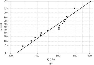
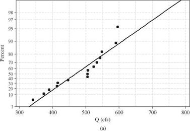
(b) Plot the annual maximum series on (i) Gumbel paper and (ii) lognormal paper.

(c) Construct a best-fit line through the nonlinear plots, and estimate the flows for return periods of 2, 10, 25, and 50 years.

Solution n = 15 (a)

Annual Maximum Discharge (ft3/s)

Rank

(m)

‘T _ n+1 Tm = m

(years)

P(X > X(m))

= 1/Tm

P (X < x(m))

= 1 – 1/Tm

596

1

16.00

0.0625

0.9375

591

2

8.00

0.1250

0.8750

549

3

5.33

0.1875

0.8125

543

4

4.00

0.2500

0.7500

533

5

3.20

0.3125

0.6875

524

6

2.67

0.3750

0.6250

507

7

2.29

0.4375

0.5625

505

8

2.00

0.5000

0.5000

505

9

1.78

0.5625

0.4375

447

10

1.60

0.6250

0.3750

416

11

1.46

0.6875

0.3125

414

12

1.33

0.7500

0.2500

390

13

1.23

0.8125

0.1875

374

14

1.14

0.8750

0.1250

342

15

1.06

0.9375

0.0625

(b) Plots of the annual maximum flow series on the Gumbel and lognormal probability papers are shown in Fig. 3.2.

Graphic Approach

Graphic Approach

Figure 3.2 Probability plot for the annual maximum series for 1961-1975 on the Boneyard Creek at Urbana, IL: (a) Gumbel probability plot; (b) lognormal probability plot.


(c) The following table summarizes the results read from the plots:


Return Period (years)

Distribution

2

10

25

50

Gumbel

470

610

680

730

Lognormal

475

590

650

700


Graphic Approach

Begin with door and window assemblies

I begin framing by building the door and window assemblies. All window headers and most door headers need top cripples (sometimes called jacks) and all rough sills need bottom cripples (see the illustration on the facing page). A chopsaw worker has probably already cut these to size and grouped and labeled them. Grab an armload and carry them to their proper locations. Check to see that the cripples match the lengths written on each header. Every header takes a cripple on each end and one on each layout mark. Pay close attention! Place bottom cripples perpendicular to the wall plates, exactly where they will be nailed in place. I also place a trimmer and a king stud next to each window opening before I do any nailing.

To make toenailing cripples to headers easier, back up the cripple with your foot before starting the first two 8d toenails (see the top photo at right). Make sure each 2x cripple is on its layout mark and flush with the sides of
the header, then drive the nails home. After nailing off one side, toenail two more 8d nails into the other side. Repeat the process until all the top cripples for each wall have been nailed to their headers.

Attaching the bottom cripples to rough win­dowsills is easier. Move the rough sill to the up­per ends of the cripples placed against the plates. There should be one cripple at each end of the sill and one at each layout mark. Drive two

Begin with door and window assembliesПодпись:Begin with door and window assemblies

Habitat

for Humanity’

16d nails about 3/4 in. from each edge of the rough sill into each cripple. When nailing near the end of 2x stock, set the nail back from the end and drive it at an angle or blunt the nail point to reduce your chances of splitting the board.

Finish the window-frame assemblies by nailing on the trimmers and king studs. This is easy to do now because you are working flat on the floor. Don’t move these units around. Keep them in place where they will be nailed to the plates. Nail the window trimmers flush with the ends of the bottom cripples. Secure the trimmers to the rough sill with just two 16d nails each. Then nail the king studs along­side them so they are flush with the top of the top cripples and with the bottom of the trim­mers. Secure the king studs on each side by driving two 16d nails into a 2x header or four or five 16d nails into a larger header. Finally, drive a nail near the top of the trimmer into the king stud. The trimmers will be perma­nently nailed later, before you install the exterior sheathing or set the windows. As for door trim­mers, wait to install them until after the walls have been raised.

With all the walls plated and the window and door frames nailed together, you’re ready to frame the walls. At this stage, it’s smart to check your work. Make sure that the framing mem­bers are flush with each other and nailed tightly together. Keep the door and window frames square. This makes for quality construction and you’ll have an easier time nailing the top and bottom plates to wall studs and door and window frames.

Distribute studs, corners, and channels

Ask your crew to distribute studs along one of the exterior through walls, with one stud per layout mark. Place the studs against the two tacked-down plates. Where corners and chan­nels are required, decide which corner style you want to use. The sidebar on the facing page

Bracing

Tumbleweed would have to withstand not only the normal wear and tear of everyday living, but also the occasional jolts and gale-force winds generated by highway travel. To prepare for this, I used what has come to be called the “screw-and-glue” method of sheathing. This means that a bead of construc­tion adhesive was squeezed onto the entire length of every framing member before 3/8” plywood sheathing was screwed (not nailed) to its surface. This makes for a structure far more resilient to lateral wind loads than sheathing secured with nails alone.

before 3/8” plywood sheathing was screwed (not nailed) to its surface. This makes for a structure far more resistant to lateral wind loads than sheathing secured with nails alone.

. Pollution-Induced Degradation of Bound Layers

Performance characteristics of bound pavement layers are known to be influenced by water-borne pollutants that cause changes in mechanical behaviour, ageing and degradation. With the exception of Portland cement concrete (PCC) pavements, this has not yet received much attention. Asphalt pavements are not seriously affected by inorganic pollutants, but most of the organic chemicals, including gasoline and motor oil, soften up or break down the asphalt binder leaving the asphaltic layer vulnerable to further degradation. Damage of the surface layer, due to ageing (stiff­ening because of ultraviolet light), traffic induced cracks and chemical degradation, opens an ingress route in the pavement system for pollutants from the surface.

In hot climates, salt can be moved by evaporating water to near the pavement surface. This may result in the expansive crystallisation of salt in voids in asphaltic mixtures (or other bound layers) just below the road pavement’s surface leading to blistering of the running surface, to cracking of the pavement and to overall degra­dation. Guidelines to the understanding and treatment of this issue are available (Obika, 2001). In temperate climates, salt (NaCl) seems, usually, not to be a sig­nificant contributor to damage of asphaltic materials. It may, sometimes, accelerate deterioration of poor quality materials, but it appears that it is water damage itself which is the primary cause (see Section 5.5). However, the chemistry of the wa­ter in the pores of asphaltic materials can have an important influence on whether stones and binder adhere efficiently. Greater alkalinity (i. e. higher pH) potentially
results in increased rates of moisture damage, although Calcium Hydroxide (slaked lime) dissolved in the water doesn’t have this effect even though pH rises (Little & Jones, 2003). In cold climates, salt has been implicated in causing damage. Ac­cording to Hudec and Anchampong (1994) certain fine grained aggregates degrade rapidly during wetting and drying cycles and during freeze-thaw cycles especially if deicing salts have been used abun-dantly. The extensive use of chlorides has also been reported to cause accelerated pavement deterioration (Dore et al. 1997, Saarenketo, 2006).

In PCC, deterioration is related to complex processes associated with physical and chemical alteration of the cement paste and aggregates. One major chemical degradation mechanism resulting from the long-term application of the popular chemical de-icer sodium chloride (NaCl) is the dissolution of calcium hydroxide (Ca(OH)2). Another common de-icer, CaCl2, is associated with a deleterious chem­ical reaction with PCC. The chemical attack is accompanied by the formation of hydrated calcium oxy-chloride according to the following reaction:

3Ca(OH)2 + CaCl2 + I2H2O ^ 3CaO ■ CaCk ■ I5H2O

This reaction is considered to be disruptive to the concrete matrix because of the expansive pressures generated. Another potential detrimental effect of the ap­plication of chemical de-icing salts is increased alkali – silica reactivity (ASR), which is a distress caused by undesirable chemical reactions between alkalis in the cement paste (Na2O and K2O) and the reactive siliceous components of susceptible aggregates. The product of the reaction is expansive in the presence of moisture, destroying the integrity of the weakened aggregate particle and the surrounding ce­ment paste. When aggregates like dolomitic limestone are used there is a possibility of alkali-carbonate reactivity, where alkalis react with carbonate aggregates. Besides these mentioned processes, there is also the possibility of external and internal sul­phate attack, which can cause deterioration. Other de-icing chemicals (magnesium chloride, calcium magnesium acetate, Ca-acetate, Mg-acetate, urea, etc.) may also have damaging effect on PCC pavement layers (MTTI, 2002).

Hydraulically bound mixtures may be considered as low strength PCC. From this point of view, the effects of the pollutants (mainly de-icers and sulphate) are similar to those on PCC pavements, except that chemical degradation, deterioration and loss of strength of the hydraulically bound layer will be quicker than in PCC layers, leading to higher stress on the layers beneath and faster degradation of the pavement.

Coarse-Aggregate Skeleton

The first step, as in the U. S. method (see Section 7.2), is determining the volume of the skeleton of coarse particles and the voids between them available for the remain­ing SMA elements. Determining the volume occupied by the coarse aggregate skel­eton consists of defining its density and testing the coarse aggregate compaction (namely, the amount of air voids remaining among the coarse grains after compact­ing). As we know, the amount of air voids in a compacted coarse aggregate may be determined using the following methods:

• With dry aggregates, using the dry-rodded test after AASHTO T19 as in the U. S. method, or using a gyratory compactor, Marshall hammer, or on a vibrating plate

• Using a special lubricating agent[38] and chosen method of compaction

The substantial difference between the dry-rodded method and other methods is the dry compaction of aggregate used in the U. S. method and the “grease” process used in the others. Explaining this issue logically, air voids determined using the dry – rodded method must be larger because of the higher resistance to the displacement of particles relative to each other, so they will not be arranged as closely as in the grease method. The use of grease will also result in less crushing of the aggregate during compaction. After all, when compacting SMA on a site, the presence of binder in the mixture lubricates it, making the displacement of aggregate particles easier. So it seems that the method using grease, though more problematic in practice, enables us to obtain results closer to reality. Any substance with a viscosity resembling the viscosity of binder at about 150°C may be employed as a lubricating agent or as a grease in the mixture. In the Netherlands, medical oil has been used for that purpose, with 1.5% (m/m) added to the aggregate mixture. The possibility of conducting the whole operation at room temperature, without heating up the oil and aggregate, is a notable advantage of this substance.

The coarse aggregate of an analyzed mixture (a sample of 4 kg) is compacted by being placed in 150 mm diameter specimen mold and undergoing 300 rotations in a gyratory compactor[39] with the external angle of rotation set on 1°. After the density of the coarse-aggregate particles (greater than 2 mm) and the air voids in the compacted aggregate are determined, the aggregate is extracted from the oil and the gradation is measured. Consequently, apart from the result of air voids in compacted coarse aggregates, some additional information is gained on the aggregates’ resistance to crushing. A compactor, when set at 300 rotations, causes overcompaction of the mix­ture and, to some degree, destruction of grains corresponding with the laydown and compaction process and after several years of service.

Another important factor that should be taken into account while analyzing air voids among coarse grains is their crushing and wearing, which occurs at the production stage of a mixture, at its laydown, and during its later service. Crushing of the grains causes the displacement of particles, hence a decrease of air voids in the coarse aggregate skeleton (post-compaction). Coupling this with the knowledge of susceptibility of the aggregate to crushing and wearing that is gained by screening the aggregate after compacting it in the gyratory compac­tor, it is necessary to increase the air voids in the designed SMA to a certain degree (e. g., to 5% instead of 4%). This should guarantee that, even after long­term service under heavy loads, there will be no bleeding of mastic (fat spots) from among the grains of a skeleton. This method of reasoning has been adopted in the Netherlands, where the air void content in compacted laboratory samples for heavy duty traffic has been increased to 5% (v/v) (Jacobs and Voskuilen, 2004; Voskuilen, 2000).

The use of aggregates susceptible to crushing alters the volume relationships in the aggregate mix in the following ways:

• The volume of the coarse particle skeleton decreases (because some of the coarse particles becomes fine particles).

• The volume of fine particles, which are not involved in the coarse skeleton’s performance, increases.

• The content of air voids in the aggregate mixture decreases.

• Consequently the quantity of air voids in the SMA drops, so the risk of overfilling with mastic increases.

Using this method, the effect of increasing air voids in the coarse skeleton has been taken into account. We should remember that air voids have been determined using the method of dry or greased compaction of coarse aggregates. In this test, only the aggregate greater than 2 mm has been used. In a real mixture, coarse grains are coated with mastic, so naturally there are particles of filler or crushed sand among the coarse particles. These particles slightly increase the content of air voids among the coarse aggregates, particularly at the first stage of an SMA’s performance. In the Netherlands the effect of an added increase of air voids among coarse particles has been called the enlarging effect. With the passage of time, the decrease of air voids among coarse aggregates occurs as a result of post-compaction, reorientation of coarse grains, wear, and the movement of fine particles.