Raise exterior through walls first

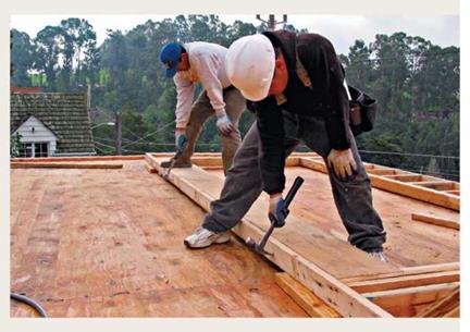
Start with one of the exterior through walls. Make sure there is no debris beneath the plates before raising the walls upright. If the wall is flat on the deck, stick the claw of a hammer into the double top plate, lift the wall up a bit, and put a 2x block under the wall. This way you can get your fingers under the wall to lift it. Keeping your back straight, use your legs to lift the wall to your waist, then take it overhead using your arms and upper body. Continue to raise the wall by pushing on the studs until it is fully upright. Once the wall is upright, hold

Remember that diagonal braces are important. Both exterior through walls are up; diagonal braces hold them securely while the other walls are raised. Use these temporary braces liberally where needed.

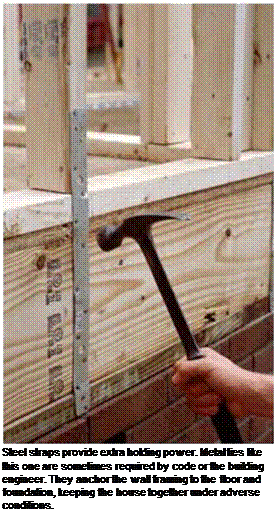
Подпись: Steel straps provide extra holding power. Metal ties like this one are sometimes required by code or the building engineer. They anchor the wall framing to the floor and foundation, keeping the house together under adverse conditions. Подпись:

Raise exterior through walls first

it steady—especially if there’s a good wind blowing—until the temporary wall braces are nailed in place.

After the wall is in position, nail a stud to each end as a temporary brace, extending it diagonally from about 6 ft. up on the corner stud down to the rim joist. Drive a couple of 16d nails into each end of the brace. On long walls, nail other braces in the middle from a stud down to the subfloor. Make sure these tem­porary braces will hold the wall until the butt walls are built and raised against it.

Use a sledgehammer to move the wall until it is right on the chalkline and flush at the ends with the correct marks on the subfloor. After

Подпись:the wall is in position, nail through the bottom plate and into the subfloor, using one 16d nail between each stud. Be sure to drive a 16d nail close to each king stud. Drive plate nails into the rim joist or into a floor joist. Nails driven through the subfloor alone don’t have nearly as much holding power as those embedded in framing lumber. Don’t nail in doorways, because you’ll be cutting out the plate later when you set the door frame.

When working on a slab, lever the bot­tom plate into position over the bolts. Slip the end of a 2×4 under the bottom plate to use as a lever. While one person works the 2×4 lever, other crew members can move the bot­tom plate in or out to align the holes with the installation bolts. In some areas, bottom plates are attached to the slab with concrete nails. In other areas, steel hurricane straps are used to tie wall framing to the floor framing and foun­dation (see the bottom left photo on p. 103). Now is the time to make sure that these fram­ing connectors are nailed to the wall frame.

CONCRETE BRIDGE DECK PROTECTION

Concrete bridge decks designed by the current AASHTO method described above have large amounts of reinforcing steel. (Some say it is enough to drive on, and that the concrete is provided just to make the ride smoother!) In the past, in areas where deicing salts are used, corrosion of the top steel caused extensive spalling that led to premature repair or replacement of many decks. In some coastal areas, saltwater spray on the bottom of deck slabs has caused similar corrosion of the bot­tom reinforcing steel.

For the foreseeable future, concrete bridge decks will continue to be reinforced with steel bars, even though revised design procedures may be adopted that permit lesser amounts. Therefore, it will continue to be necessary to protect those bars against corrosion. Reinforcing bar corrosion can be prevented or forestalled by a number of means, including:

• Making concrete more resistant to penetration of chlorides (less permeable; see HPC in Art. 4.5.1)

• Preventing chlorides from penetrating the concrete by applying concrete sealers or waterproofing membranes

• Applying a physical coating to the bars to prevent contact between the chlorides and the bars

• Adding a corrosion-inhibiting admixture to the concrete mix

• Installing cathodic protection

Concrete Permeability. As discussed above, improvements have been made in the quality of concrete, and in the development of special concretes, in an effort to reduce the amount of chlorides reaching the reinforcing steel. These improvements themselves may be adequate to prevent premature corrosion, especially in areas where the applica­tion of deicing salt is moderate. In areas of greater rates of salt application, it may be necessary to provide supplementary protection of the types listed above.

Concrete Sealers. Sealers are available that can reduce the permeability of hardened concrete. Forms of silanes and siloxanes are among the best sealers. In some cases, however, the field performance of concrete sealers has not lived up to expectations based on laboratory testing. When selecting a sealer, one should avail oneself of the most current field evaluations of effectiveness over a reasonable period of time, and not rely solely on the claims of the manufacturer’s representative.

Waterproofing Membranes. Where an asphalt concrete overlay is placed on a bridge deck in an area where deicing salt is used, the salt will penetrate through the overlay unless an impermeable membrane is installed on the concrete deck. Both hot and cold rubberized materials are available, as well as more labor-intensive built-up systems. Built-up systems, like roof systems, combine layers of fabric alternated with applications of a bituminous coating. Built-up systems may cause the asphalt overlay to slide on steep grades or superelevation. All kinds of membranes are subject to development of blisters due to entrapped water vapor if the membrane cures before the vapor escapes. This can generally be prevented by placing the membrane when the temperature in the deck is decreasing, that is, during the late afternoon or evening, rather than in the morning or midday.

Epoxy-Coated Reinforcing Steel. The coating that has received the most widespread acceptance for physical encapsulation of the reinforcing bars is fusion-bonded epoxy coating. Some agencies require epoxy-coated bars for the top mat only; others require them top and bottom.

The epoxy coating is applied electrostatically in powder form to cleaned and heated bars in a continuous operation, and rapidly quenched immediately after being applied. The coating is quite hard, but must be handled carefully to avoid damage. Nylon slings are used to lift the bundles, and padding is used within the bundles. Specifications that allowed a small but liberal percentage of openings in the coating have recently been reexamined and tightened. Following the widespread adoption of epoxy-coated reinforcing steel, some unfavorable experience in marine structures has put somewhat of a damper on its enthusiastic acceptance.

A disadvantage of epoxy coating is that the coating reduces the bond between the bars and the concrete, requiring longer lap splices.

Galvanized Reinforcing Steel. About the time when many states began to install epoxy-coated bars for experimental evaluation, some states experimented with galva­nized bars. This was based partly on the contention of some corrosion experts that flaws in epoxy-coated bars would result in aggravated corrosion at those flaws. Pennsylvania adopted galvanized reinforcing steel for a time as its primary means of protecting the bars. Now at least one state has changed to that policy.

Galvanizing does not provide a permanent barrier, but creates a sacrificial coating, and consequently would be expected to have limited life expectancy when exposed to sufficient quantities of chlorides over a period of time. Because of the electrochemical nature of the way galvanizing prevents corrosion, it should not be used on only one mat of reinforcement.

Corrosion-Inhibiting Admixtures. Another means of protecting against corrosion of reinforcing steel, without application of physical coating to the bars, is the incorporation of a corrosion-inhibiting admixture in concrete. The amount of chemical added to the concrete mix is proportioned to the amount of chlorides expected to penetrate to the reinforcing steel. Therefore, the degree of effectiveness of the inhibitor is related to the accuracy of that prediction. Higher dose rates will provide greater protection, but at greater cost. A lower dose rate may not provide the necessary protection.

Some inhibitors have undesirable effects on other properties of the concrete, but one admixture that is effective without side effects is calcium nitrite.

Available publications do not provide specifications or guidelines for the evalua­tion and comparison of corrosion-inhibiting admixtures, requiring users to rely on information provided by product manufacturers. However, a National Cooperative Highway Research Program project is planned to develop test procedures to evaluate and compare the effectiveness of corrosion inhibitors, and to recommend performance criteria for their acceptance.

Cathodic Protection. Since rebar corrosion is an electrochemical reaction, an effective means of preventing or arresting corrosion is cathodic protection. The two main types of cathodic protection are sacrificial anode and impressed current. In the sacrificial anode system, disks of metal are installed at intervals in the deck before placement of the deck or overlay concrete. Corrosion activity involves the consumption of this metal rather than rusting of the bars. The impressed-current method requires the input of electricity, and therefore requires an electric source and is dependent on the continued monitoring and maintenance of the system. Power consumption is low. One reason cathodic protection was late in being implemented is that it involves the expertise of electrical or corrosion engineers rather than the structural engineers who are normally responsible for bridge design and rehabilitation.
Sources and Fate of Water Contaminants in Roads

Lennart Folkeson[12], Torleif Bskken*, Mihael Brencic, Andrew Dawson, Denis Francois, Petra Kunmska, Teresa Leitao, Roman Licbinsky and Martin Vojtesek

Abstract This chapter gives an overview of sources, transport pathways and targets of road and traffic contaminants. Pollution sources include traffic and cargo, pave­ment and embankment materials, road equipment, maintenance and operation, and external sources. Heavy metals, hydrocarbons, nutrients, particulates and de-icing salt are among the contaminants having received the greatest attention. Runoff, splash/spray and seepage through the road construction and the soil are major trans­port routes of pollutants from the road to the environment. During their downward transport through road materials and soils, contaminants in the aqueous phase inter­act with the solid phase. In saturated media, diffusion, advection and dispersion are the major processes of mass transport. In unsaturated soil, mass transport strongly depends on soil-moisture distribution inside the pores. Sorption/desorption, dissolu- tion/precipitation and ion exchange reactions are the most significant chemical pro­cesses governing pollutant transport in soils. Redox conditions and acidity largely regulate heavy-metal mobility. Many heavy metals are more mobile under acidic conditions. Plants close to heavily trafficked roads accumulate traffic pollutants such as heavy metals. Heavy metals, organics, de-icing salt and other toxic substances disturb biological processes in plants, animals, micro-organisms and other biota and may contaminate water bodies and the groundwater. European legislation puts strong demands on the protection of water against pollution. Road operators are responsible for ensuring that the construction and use of roads is not detrimental to the quality of natural waters.

Keywords Contaminant ■ pollution ■ flux ■ soil process ■ pathway ■ chemistry ■ biota ■ biology ■ legislation

Designing a wall system

Once the stud size and spacing and the framing system have been selected, it is time to consider how to brace the building to resist the forces of wind, earthquakes, and eccentric loading. Will diagonal bracing be ade­quate, or should the building be braced with structural sheathing and/or shear walls? This question is best answered in the context of the design of the building as a whole, considering the other materials that complete the wall system. How is the wall to be insulated? Where are the openings in the wall for doors and windows? Will there be an air-infiltration barrier? What material will be used for the exterior finish? The details relating to these issues are addressed in this chapter, along with some suggestions for their appropriate use. How these various details are assembled into a complete wall system depends on local climate, codes, tradition, and the talent of the designer.

sizing headers

Headers are structural members over openings in walls for windows or doors. Header size depends on wood species and grade, loading, header design, and rough­opening span. Following is a rule of thumb for sizing a common header type, the 4x header (see 68B):

For a single-story building with a 30-lb. live load on the roof and 2×4 bearing walls, the span in feet of the rough opening should equal the depth (nominal) in inches of a 4x header. For example, openings up to 4 ft. wide require a 4×4 header and up to 6 ft. wide, a 4×6 header.

advanced framing

Advanced framing minimizes the amount of structural material that is required to hold up the building. The greatest impact on framing efficiency can be made in the walls because wall construction has evolved in such a way that the typical wall is overbuilt. Floors and roofs are constructed reasonably efficiently because the design challenge has been to span horizontally with an economy of materials. Standard framed walls, however, contain numerous extraneous and oversized elements. The elimination and downsizing of wall members not only saves lumber, it also lowers the effect of thermal bridging, thus saving energy. Advanced framing of walls is discussed in this chapter (see 74-76).

ALTERNATIVE FRAMING METHODS

In renovation, it’s not always possible to assem­ble a wall on the deck and tilt it up. There may not be enough room, shoring may be in the way, or sloping floors may frustrate attempts to cut studs accurately in advance. In those cases, it may be easier to build the wall in place, piece by piece.

Building a partition in place. Start by position­ing the plates and tack nailing them to joists (or blocking) above or below. Although it’s most common to snap a chalkline on the floor and plumb up to the top plate, it doesn’t really matter which plate you attach first, unless there’s a com­pelling structural or design reason. If you’re erecting a bearing wall, for example, center its sole plate over the appropriate girders or bearing walls below. But if you’re trying to align a non­bearing partition with a rafter above, set the top
plate first and plumb down to establish the sole plate. If possible, face-nail the plates with two 16d nails at each joist crossing.

Mark the stud intervals onto the plates, and then—especially if floors or ceilings slope— measure the stud lengths individually. Cut the studs slightly long (Й6. in) so that they fit snugly. Toenail each end of the studs with three 10d nails or four 8d nails, angling them roughly 60° from horizontal. Use a spirit level to level the headers. Use three 16d nails to end-nail a header through the king studs on either side. Then face-nail trim­mer studs to the kings, staggering 10d or 12d nails every 16 in.

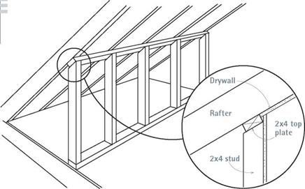
Framing beneath slopes. Framing beneath stair stringers and rafters isn’t difficult if you measure carefully and use an adjustable bevel. Mark off 16-in. intervals along a 2×4 sole plate, nail it to the floor, and then plumb up to the underside of the rafter or stringer to mark the top plate.

Cut the top plate to length, and nail it to the underside of the sloping rafter or stair stringer before using a plumbed board to mark off stud intervals along the top plate.

To establish the angle at which you’ll cut the top of the studs, plumb a piece of 2x stock in

image339I Sizing Gable-End Studs

image340

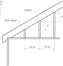
After marking off 16-in. stud centers onto the sole plate, plumb up and transfer the stud marks to the rafter or top plate. Once you’ve cut two consecutive studs, you’ll know the difference in length between adjacent studs, indicated by “X."

front of the top plate and use an adjustable bevel to duplicate the acute angle at which they inter­sect. (Set your circular saw to the angle of that bevel.) Holding a straight board against 16-in. on-center marks on the sole plate, plumb and mark the tops of two adjacent studs. The differ­ence in their lengths—represented by the Xin "Sizing Gable-End Studs,” above—will be con­stant for all successive pairs. Toenail the studs with four 8d nails on each end.

Establishing kneewalls. Kneewalls are short partitions, about knee high, which isolate the largely unusable space where the rafters approach the top plates of the exterior walls. Kneewalls usually run parallel to the roof ridge and consist of a single top plate and sole plate, with studs spaced 16 in. on center. Position the sole plate and plumb up to the underside of the rafters to mark the top plate. Using an adjustable bevel, copy the angle at which the rafters inter­sect, using a plumbed spirit level or board.

Nail the top plate with two 16d nails per rafter and the sole plate with two 16d nails per joist.

Cut across the faces of the studs in the angle established by the bevel gauge. (Note: This is not a bevel cut, but a square cut at an angle.) To attach the studs to the plates, toenail each end with 8d nails.

Demolition

Before demolishing an old wall or framing up a new one, determine whether it’s a bearing wall. If so, erect shoring if needed, and have a plan for rerouting electrical cables, pipes, or heating ducts in existing walls. О the electrical power before cutting into finish surfaces—and use a voltage tester to be sure the power’s off.

Practical Guidelines for Design

7.4.2.1 SMA Constituents

Coarse aggregates of 2/6 mm are not permitted in an SMA mixture with a grada­tion of 0/11 mm just to guarantee a gap gradation. The sand fraction has to consist of a minimum of 50% crushed stone, whereas the content of air voids according to Rigden and the bituminous number* should form the basis for selection of the filler. As in many other countries, the amount of stabilizer is based on draindown testing.

The road binder 70/100,* and in special cases modified binder, should be used in SMA. No Reclaimed Asphalt Pavement (RAP) is allowed in SMA in the Netherlands.

7.4.2.2 Designing an Asphalt Mixture

Reading the recommended fixed binder content in SMA from the standard marks the beginning of design. This quantity depends on the SMA gradation; the bigger the maximum aggregate size in a mix, the lower the intended amount of binder. It is necessary to stress again that the accepted amount of binder is a constant value; hence it is not subject to change in the design stage but is to be matched with an aggregate mix.

The amount of binder is fixed prior to establishing the filler content. The con­tent of filler (particles less than 0.063 mm) must fall within the range of 6-10% (m/m). Limestone filler is preferred; since its content of Rigden air voids is known, its behavior in the mixture is somewhat predictable.8

Fixing the amount of the sand fraction is based on the indicated constant ratio of this fraction to the quantity of filler. This ratio amounts to 65:35 (m/m) if the densi­ties are comparable with the reference density.

It has been accepted in the later stages of design that the binder content and the ratio between the filler and sand are fixed and that only the coarse aggregate content is subject to change (design). Of course, the higher the coarse aggregate content, the lower the sand-filler content. As we remember from Chapter 6, for such an assump­tion with a variable quantity of coarse aggregate of the same origin, the VMA will be subject to change.

Finally, the content of the coarse-aggregate fraction should amount to between 72.5 and 82.5% (m/m) according to Dutch regulations, so it is increased by 2.5% (m/m) in comparison with the most frequently used requirements (70-80% [m/m]). This is directly related to the higher requirements for the air voids content in heavy- duty pavements, at the level of 5% (v/v) (in other countries such pavements typically require 3- 4% [v/v]).

Binder and Stabilizer (Drainage Inhibitor)

A constant, fixed binder content, exclusively dependent on the size of the maximum particle, D, in an aggregate mix is the most unusual feature of the Dutch method. When designing SMA, the binder content for a given gradation should be taken from the regulations; for example, an SMA 0/11 for heavy-duty traffic should have a binder content of 6.5% (m/m). The quantity of binder remains unaltered; it is to be matched with a proper gradation of the aggregate mix. In other words, in the Dutch method, for a specified SMA 0/11, one has to design an aggregate mix so that it will contain 6.5% of binder with air voids at the level of 5.0% (v/v)[40] [41].

In many countries in the practice of designing asphalt mixtures it used to be said that the optimal amount of binder has been matched with a given aggregate mix. The Dutch method recommends the reverse. One could say that during the design the optimal aggregate mix had been matched with a given quantity of binder.

. PLUMBING AND SECURING THE WALL

Once the wall is up, nail the bottom of the brace so the wall will stay upright as you fine-tune its position. Use a sledgehammer to tap the sole plate till it aligns with your chalkline on the floor. As you adjust, continuously check for plumb, using a 6-ft. level. If you unnail the brace to plumb the wall, have workers support the wall until you’ve renailed it.

Once the bottom plate lines up with the chalk­line, drive two or three 20d nails through the plate, into the joists or blocking below, so the wall can’t drift. Methods for securing the top of the wall vary. If you’re framing an addition and have wide-open space, typically two walls inter­secting at right angles are raised, plumbed, and braced, and then tied together by overlapping top plates.

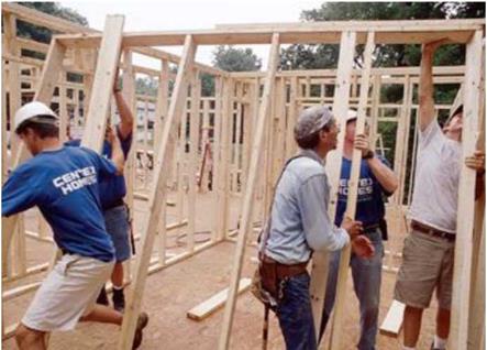
Подпись: Raising walls Two workers can raise an unsheathed stud wall 8 ft. to 10 ft. long. But if it's much longer than that or if it's sheathed, assemble a larger crew or use wall-lifting jacks to raise it. Raising walls safely takes prep work: Clear the deck of tools, scrap lumber, and other items you might trip over. Nail the top of a diagonal brace 1 ft. below the top plate, using a single 16d nail so that the brace can pivot as you raise the wall; and prenail a 2x block into floor framing so you can quickly nail the bottom of the diagonal brace once the wall is plumb. If you are raising an exterior wall, first nail 2x stops to the outside of the platform so the bottom plate can't slide off the deck during the operation. If you are raising a partition within an existing structure, expose the ceiling joists or end-wall studs you'll nail the partition to. If joists run parallel to the new partition, add blocking between the joists beforehand, as shown in "Partition Parallel with Joists" and "Blocking for Sole Plates" on p. 166. Here are three tips for raising walls: ► As shown in the photo below, several workers straddling the top plate should drive hammer claws into the top plate, lift in unison, and slide 2x blocks beneath the top plate so they can get a good grip before actually lifting. ► Lift with your legs, not with your back. ► If your crew is small, set two sawhorses nearby, perpendicular to the wall; the horses will support the wall once the crew has raised it waist-high, allowing them to reposition themselves so they can push the wall up the rest of the way. image336But if you’re raising a partition in an existing room, you’ll usually nail the top plate to ceiling joists. Invariably, space is tight indoors, and you’ll often need to gently sledgehammer the par­tition into place, alternating blows between top and sole plates till the wall is plumb. Alterna­tively, you can gain room to maneuver by first nailing the upper 2×4 of a doubled top plate to the exposed ceiling joists—use two 16d nails per joist—before raising the wall. Tilt up the wall, slide it beneath the upper top plate, plumb the wall, and then face-nail the top plates together using two 16d nails per stud bay. Finally, finish
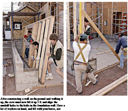
image338
nailing the sole plates, driving two 16d nails into the joists or blocking below. In the corners, use 10d or 12d nails to toenail the corner studs to blocking or existing studs; use 16d nails if you can face-nail them. Adding blocking to existing framing is discussed on p. 165.

Porous Asphalt

In countries that suffer from large amounts of rainfall, the asphaltic wearing sur­faces are often constructed of open graded asphaltic mixtures. The high perme­ability of these wearing surfaces ensures a fast drainage of the water away from

Porous Asphalt

Fig. 5.15 (a) bad road visibility conditions (b) hydroplaning and ‘splash and spray’ (Erkens, 2005). Reproduced by permission of N. Kringos

the surface, avoiding hydroplaning and bad visibility conditions due to ‘splash and spray’, Fig. 5.15, and thus improving the overall road safety.

Porous asphalt uses aggregate with a moderate to coarse median particle size and a very steep grading curve – i. e. the majority of the stones in the mixture are of a similar size. This has the effect of developing a mixture with a very high air void volume (20-30%) with stones only adhering to each other by virtue of the films of bitumen at their point of contact. In this way its porosity is very high compared with conventional asphaltic material and water does not easily collect on the surface during rainstorms.

An added benefit not included in the original concept, but now an important driv­ing force for the wider adoption of porous asphalt surfacings is the reduced traffic noise from pavements with these surfacings. The porous nature reduces tyre-surface interaction sounds and acts as a partial absorbent of other vehicle induced noise. Typically they provides a 3-5 dB(A) noise reduction over conventional pavement surfacings. Even greater benefits can be achieved by using two-layer porous asphalt with a finer, filter, layer over a coarser, drainage layer. Noise reduction may then be 8 or 9 dB(A) quieter than conventional asphaltic mixtures and 4 dB(A) quieter than a single-layer porous asphalt.

As the surfacing is so permeable, rain can drain vertically into the porous asphalt layer before being conveyed laterally within the pavement. Typically a porous as­phalt surfacing will have a thickness of between 20 and 100 mm and be placed on top of an impermeable asphaltic base. Hence, water flowing in the surfacing cannot continue to flow vertically but is forced to travel sideways, exiting from the layer at its edge. Unless this edge is free, special attention must be paid as to how the water is to be collected and led away from the pavement. An impermeable edge, such as a conventional kerb, would dam the water within the layer. Consequently special kerbs with inlets and pipe systems have been developed to lead the water into a conventional surface drainage system (Highways Agency, 1997).

Despite the advantages of the material in providing relatively dry surfaces in wet weather, the material and its use pose a number of problems:

1. Lack of durability. Careful mixture design is needed to ensure that there is enough bitumen to coat the stones and ensure longevity of performance – too much and the mixture may rut too readily and the pores become blocked by bitumen (preventing drainage). Too little bitumen and ravelling will be likely (as described in Section 5.5.1), particularly in cold weather when ice could form in the pore space forcing the topmost layers of stone loose. An added issue is that the greater opportunity for bitumen to react with atmospheric oxygen, because of air in the voids, tends to lead to early embrittlement of the bitumen (Herrington et al., 2005). Bitumen film thickness is, thus, of particular importance. Hence, both design and construction practice require careful attention, perhaps more so than for conventional asphaltic mixtures. More detailed coverage of this topic is beyond the scope of this chapter, but interested readers may wish to consult NAPA (2004).

2. Clogging due to ingress of particulates. Small particles and dust, that comes from the environment, blown soil, engine wear, brake wear and from cargoes (see Chapter 6, Section 6.2), tend to get washed into the pore space of the porous asphalt, thereby blocking it. In thin porous surfacings on high-speed roads it ap­pears that reduction in permeability is not of great concern. After some initial de­terioration, further clogging is often not significant, probably because high-speed traffic develops high transient water pulses in the pores of the asphaltic mixture during wet weather, causing a self-cleansing action (Bendtsen et al., 2005). In slower speed roads this action is not evident and clogging is, typically, pro­gressive. These authors monitored an urban test road in Denmark comprising 3 porous asphaltic surfacings and a control surface (Table 5.6).

Using an infiltrometer somewhat like that of Cooley (1999), see Section 5.4.1, Bendtsen et al. (2005) observed, Fig. 5.16, that clogging developed quite rapidly in the finer asphaltic pavements. The two porous pavements with 5 mm aggre­gate, Sections II and III, were effectively clogged after 15-20 months whereas Pavement I with 8 mm aggregate remained in a much better condition. The rea­son for this clogging is believed to be the dirt and fine material from the adjacent dense asphaltic concrete pavement being dragged onto the porous pavements by vehicle tyres, since clogging first appeared at the position nearest to the reference section.

Table 5.6 Danish test road construction (after Bendtsen et al., 2005)

No

Type

Top-layer

Bottom-layer

Thickness

[mm]

Aggregate size [mm]

Thickness

[mm]

Aggregate size [mm]

I

Porous asphalt

25

5/8

45

11/16

II

Porous asphalt

20

2/5

35

11/16

III

Porous asphalt

25

2/5

65

16/22

IV

Dense asphaltic mixture

30

0/8

70

Подпись:Porous Asphalt«Г

I 60

E

50

40

30

о

£ 20

о

Подпись: Fig. 5.17 Porous asphalt cleaning machine. Reproduced by permission of the Danish Road Institute

E [11]

3. Cold weather clogging by ice and snow. BackstrOm and BergstrOm (2000) evalu­ated the function of porous asphalt in cold climates using a climate room. At the point of freezing point, the infiltration capacity of porous asphalt was approx­imately 50% of the infiltration capacity at +20°C. They simulated conditions of snowmelt by exposing the porous asphalt to alternating melting and freezing over a period of 2 days and found that the infiltration capacity was reduced by approximately 90%.

To overcome clogging, cleaning devices have been developed. These (Figs. 5.17 and 5.18) typically comprise high pressure water jets that aim to disturb and erode fines resting in the pores of the porous asphalt, washing them to the surface from where they may be vacuum-collected by the cleansing machine. It is interesting to note that the results of Bendtsen et al. (Fig. 5.16) show that there is not a significant reduction in the level of clogging due to cleaning (compare ‘before’ (b) to ‘after’ (a) readings in the figure) and that cleaning did not bring back performance close to the original function.

Porous Asphalt

Fig. 5.18 Porous asphalt cleaning machine and diagram of active part. Reproduced by permission of Sakai Heavy Industries

5.3 Conclusions

A range of equipment exits to determine permeability of asphaltic mixtures both by in-situ and laboratory testing. At present the values of permeability collected seem, mostly, to be being used for relative performance assessments and they are not much integrated in whole-pavement water regime modelling. Current advances in computational engineering and mechanical and physio-chemical testing enable the identification of the actual physical processes of water-induced damage in asphaltic mixtures and the evaluation of their effects on the total mixture response. It is hoped that, over a period of time, availability of these resources will enable a gradual tran­sition in mixture design from a design-by-testing approach to an approach in which design is by identification of the optimal choice of individual mixture components on the basis of their physio-chemical and mechanical characteristics and interac­tions. The increasing use of porous asphalt for noise reduction and spray reduction purposes is an important challenge to the pavement engineer. Purposely allowing water into the structure provides the opportunity for much greater and faster ravel­ling. There are also concerns about clogging due to washed-in fines and due to ice formation. Rehabilitating clogged porous asphalt without causing premature dam­age is a challenge.

Acknowledgments Some of the work described in this chapter has been performed with financial, computational or experimental support of Ooms Nederland Holding Bv, the Section of Structural Mechanics of TU-Delft (both in the Netherlands) and the Turner Fairbanks Highway Research Center of the US Federal Highway Administration. The authors wish, therefore, to express their thanks to Dr. A. de Bondt, ir. C. Kasbergen and Dr. J. Youtcheff respectively for this.

Adjustment for the Run

For every 12" of common rafter run, there is 16.97" (17" approx.) of run for hip and valley rafters. Multiply the run in feet of the common rafter by 16.97" (17" is commonly used) to get the run of the hip or valley rafter.

Adjustments for the Top and Bottom Cuts

The cut mark will be made similar to the common rafter cut mark, except that the hip-val scale on the speed square will be used instead of the common scale to mark the line to cut. (See “Rafter Cut Length" and “Angle Cuts" earlier in this chapter)

If a framing square is used, apply the same procedure shown previously, except use 17" instead of 12" along the blade of the framing square.

These procedures assume a hip or valley corner of 90 degrees.

Bottom Adjustment

Hip Rafter Length (HRL) = Hip rafter length before adjustments (HRBA) – У diagonal thickness (DT) of rafter – thickness (T) of rafter (У thickness top and bottom combined).

HRL = HRBA – У DT – T

These figures are based on a 90-degree building

corner.

Valley Rafter Length = Valley rafter length before adjustment – % diagonal thickness of rafter.

(The % thickness factors cancel each other out.)