Sources

Pollution sources include five main groups: traffic and cargo, pavement and embank­ment materials, road equipment, maintenance and operation, and external sources. Road and traffic pollutants having received the greatest attention include heavy metals, hydrocarbons, nutrients (mainly nitrogen), particulates and de-icing salt (Table 6.1). Recently, precious metals worn from catalytic converters have also been given attention. In addition to these pollutants, a range of gaseous pollu­tants is emitted as a result of fuel combustion. These are to a large extent aerially transported away from the road area, and this issue is beyond the scope of this overview.

The amount of pollutants originating in road and traffic depends on several aspects related to road design, road materials, road maintenance and operation, types of fuel used and traffic characteristics such as volume of light and heavy vehicles, speed and driving behaviour (Pacyna & Nriagu, 1988; Legret & Pagotto, 1999; Sarkar, 2002; Warner et al., 2002; Bohemen & Janssen van de Laak, 2003).

To a great extent, heavy metals, polyaromatic hydrocarbons (PAH) and, to a varying extent, other pollutants (e. g. sodium and chloride from de-icing) emitted from road and traffic sources accumulate in the soil in the vicinity of the road (WHO, 1989; Munch, 1992; Zereini et al., 1997). This continuous accumulation poses a long-lasting stress to vegetation, animals, soil microflora and other compart­ments of the ecosystems close to roads but seldom gives rise to acute toxic effects. On the contrary, acute toxic effects may occur following the infrequent events of traffic accidents involving dangerous goods such as petrol and diesel as well as acids and other chemicals, sometimes in large quantities. It should be noted here that both concentrations and load are of importance – instantly high concentrations may cause acute damage or may be lethal whereas the long-term performance of the ecosystem (component) may be more influenced by the total load of pollutants over a period of time. Die-off of roadside trees or twigs due to the use of de-icing salt is an example of damage being caused either by instantly high concentrations or the load over time, or both (Backman & Folkeson, 1995).

Table 6.1 Sources of contaminants originating in different road and traffic sources

Подпись: Ш u Подпись: І5=

o3

£P

О

Traffic and cargo

Car bodies

x

x

x

x

Tyres

x

x

x

Brake pads Catalytic converters

x

x

x

Fuel, fuel additives

x

x

x

x

x

Lubricants

x

x

Cargo

x

x

x

x

x

x

x

Spillage

x

x

x

x

x

Pavement &

Aggregate

x

x

embankment

Bitumen

x

x

x

materials

Secondary (alternative)

x

x

x

x

x

materials

Road equipment

Crash barriers, signposts

x

x

Road markings

x

x

Maintenance &

Winter maintenance

x

x

x

x

operation

Summer maintenance

x

x

x

x

x

Painting

Vegetation control

x

x

x

x

Snow banks and heaps

x

x

x

x

x

x

x

x

x

External sources

Litter

x

x

x

x

x

x

Excreta

x

x

x

x

x

Long-range air pollution

x

x

x

x

x

x

x

x

Source

Contaminant type

5=

c3

cd

“Cargo”: spills and littering from cargoes as well as compounds released upon accidents in­volving dangerous goods. “Common heavy metals” here include iron, copper, zinc, cadmium, lead, chromium, nickel, cobalt and vanadium. “Platinum group elements” here include rhodium, palladium, iridium and platinum. Information from literature reviews including Sansalone & Buchberger (1997), James (1999), Leitao et al. (2000), Ek et al. (2004), Folkeson (2005).

Raise exterior butt walls next

Raise exterior butt walls next

Once you’ve finished with the exterior

Подпись: STEEL STRAPS PROVIDE EXTRA HOLDING POWER. Metal ties like this one are sometimes required by code. They anchor the wall framing to the floor andRaise exterior butt walls next

Подпись: foundation, keeping the house together under adverse conditions.
Подпись: TACK THE DOUBLE TOP PLATE. When raising interior walls, it often helps to tack part of the double top plate to the wall, as shown here, until after the wall has been raised. Later, this short section of double top plate can be positioned to overlap the top plate in an adjacent wall.

16d nail between each stud. Be sure to drive a 16d nail close to each king stud. Drive plate nails into the rim joist or into a floor joist. Nails driven through the subfloor alone don’t have nearly as much holding power as those

through walls, its time to raise the exterior butt walls. Remember that vou want the butt walls’ double top plates to be about 3/ in. longer than the Lop plates (5’A in. for 2×6 walls) so that they will lap over the through walls’ top plates. This can make it difficult to

Raise exterior butt walls next

Подпись: IT'S A HOUSE! When the last wall has been raised, something special happens. What was once just a jumble of framing lumber on the deck all of a sudden feels like a house with real rooms.

raise the butt walls, though, because the dou­bletop plate sticks out at both ends.

There are a couple of tricks for making it easier to raise these and other butt walls.

One approach is to double-plate the entire butt wall except for a short section— say, 4 ft. or5 ft.—at each end. Cut these short pieces and tack them to the wall to keep them close at hand (sec the bottom photo on the facing page). Then nail them on after raising the wall. Alternatively, vou can leave off a section

4 4

of the double top plate from one end of the walk then jockey the opposite end into position with a couple of helpers. With a little experience, you’ll learn these shortcuts.

Raise interior walls from the longest to the shortest

As you raise and position each wall, nail the jendstud of each intersecting butt wall flush with the comer or channel on the through kail. Use three Uxl nails: one 2 ft. up from the
bottom, one 2 ft. down from the top, and one in the center. After all the walls are raised, stop and admire your work. 1 ts like magic: As you stand in individual rooms, you can see the shape of the house.

In many areas of the country, a small room is often built to house the hot water heater and a furnace or forced-air heating unit (FAU). A platform must be built in this room so that the heating unit will have return air from below. The platform is often built 30 in. off the floor with a 20-in. by 20-in. opening in front, as shown in the illustration on p. 104. Check with your heating contractor for exact dimensions in your area.

Tie off the double top plates

Подпись:Подпись:Подпись:Nailing the lapped double plate into the adjoining top plates ties the entire framed structure together. This important task, when done accurately, makes it easy to plumb and straighten the walls. II you are a gymnast, like
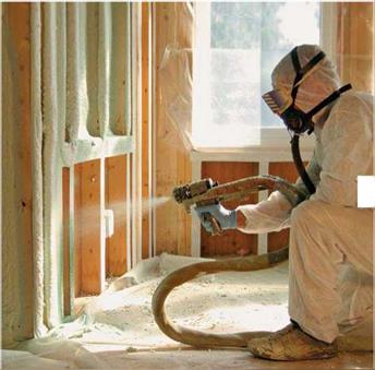
The Open-Cell vs. Closed-Cell Debate

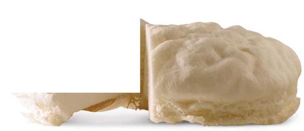
In most closed-cell foams, such as those made by Corbond®, an HFC blowing agent is captured in the foam’s cell structure. This gas has a better thermal performance than the air-filled open-cell foam and gives it a higher overall R-value. However, while HFC – blown closed-cell foam might initially have an R-value as high as R-8 per in., its R-value diminishes as the blowing agent evaporates through cell walls and is replaced by air. Closed-cell foam’s "aged" R-value is roughly R-6 per in. Some manufacturers produce water-blown closed-cell foams. These foams have the same performance properties as HFC-blown foam, but slightly lower R-values, at around R-5.5 per in.

Closed-cell foam’s greater density, 2 lb. per cu. ft. compared with open cell’s 1/2 lb. per cu. ft., also increases its R-value and offers it the rigidity that open-cell foam lacks. Tests at the National Association of Home Builders research center confirmed that closed-cell foam can actually increase the shear strength of conventionally framed walls by 30%. Closed-cell foam also has a low vapor-permeability rating (roughly 0.5 perms at a thickness of 3 in.) and is con­sidered a class-II vapor retarder, meaning it’s semi-impermeable.

The Open-Cell vs. Closed-Cell Debate

OPEN CELL

Density: Vi lb. per cu. ft. R-value: 3.5 per in.

Vapor permeability: Permeable Air barrier: Yes Blowing agent: Water

Подпись: HiThe Open-Cell vs. Closed-Cell DebateПодпись: Proper prep yields the best installation. While spray foam is installed by a pro, it's your responsibility to prep the site. Masking windows, electrical boxes, and even floors is important if you want the foam contained to wall, roof, and floor cavities. Anyone on site during the installation should be outfitted for optimum protection.

Open-cell foam, made by companies such as Icynene® and Demilec®, has a greater expansion rate than closed-cell foam. It expands 100 times its initial volume (closed­cell foam expands only 30 times its initial volume), so less of the foam is needed to insulate a house.

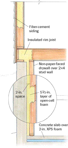
Open cell’s one major weakness is its lower R-value, roughly R-3.5 per in. This means that when used in a 2×4 exterior wall, it will create an assembly that’s approxi­mately only R-12, which won’t meet code in most parts of the country.

Installing Lots of Foam Isn’t as Effective as You Think

A lot of energy-conscious architects and builders shoot for the highest R-values they can possibly attain: R-40 walls and an R-60 roof. However, R-values aren’t necessarily an accurate reflection of overall thermal perfor­mance. For example, you would think that an R-40 wall full of spray foam would per­form twice as well as a wall sprayed to R-20 with the same foam, but that’s not the case.

Chris Porter, the building-science and code manager for BioBased Insulation®, explains that "open-cell foam reaches a point of diminishing returns at around
5 in. That threshold is even lower for closed­cell foam, which experiences diminishing returns at around 3 in. or 4 in." Those thick­nesses create assemblies between R-20 and R-24, which by the numbers seem a little weak. Each additional inch of spray foam

More Than One Way to Use Spray Foam: Two Experts Weigh In


Most experts agree that spray polyurethane foam is a revolutionary product. What they don’t always agree on is the way it’s installed and integrated into a building assembly. To shed some light on this debate, energy-efficient building expert Bruce Harley (Westborough, Mass.) and architect Peter Pfeiffer (Austin, Texas) explain how they use spray polyurethane foam to insulate the homes they build.


The Open-Cell vs. Closed-Cell Debate

PETER

PFEIFFER

No other insula­tion system I am familiar with provides the real R-value that spray foam does, ac­complishes the air-sealing it does, or thwarts vapor flow as well.

Closed-cell spray foam greatly re­duces the chance for condensation within the framing of a home. I think it is critical that houses be built to thwart vapor flow correctly.

I insulate all homes pretty much the same way. However, in colder climates,

I use 2×6 exterior walls and insulate the basement or crawlspace.

Peter Pfeiffer of Barley & Pfeiffer Architects is a

LEED-accredited architect and building scientist who has spent the past 30 years developing high – performance building-design strategies.


R-17

WALLS


R-19

BASEMENT


Bruce Harley of Conservation Services Group is

an energy-efficient construction expert and author of Cut Your Energy Bills Now (The Taunton Press, 2008).


Fiber-cement

siding

Vapor barrier extends 12 in. up wall and is secured with mastic.


Damp proofing


The Open-Cell vs. Closed-Cell DebateThe Open-Cell vs. Closed-Cell Debate

Подпись: Spray Foam for the Eco-Conscious

Consuming fossil fuels to make products intended to conserve fossil fuels makes little sense to a lot of people. All spray foams contain a certain level of petroleum in their A component and in their B component. Manufacturers such as BioBased Insulation, Demilec, and Icynene have created more environmentally benign spray-foam products by reducing the amount of petroleum used in their B component. They replace a portion of the polyol resin, which makes up 20% to 30% of the B component, with a renewable resource such as soybean or castor-bean oil. Apex even has a sucrose-based polyol. Manufacturers say that the transition to bean oil or sucrose doesn’t alter the look or the performance of open – or closed-cell foam in any way.

The amount of soybean, castor bean, or sucrose found in foam varies by manufac­turer, so identifying the “greenest” foam might not be so easy. According to the U. S. Department of Agriculture, only 7% of a spray-foam product needs to be made of a renewable resource to be labeled as a bio­based foam. This, of course, doesn’t factor in the petroleum fueling the crop-cultivation process.

yields little performance. In fact, while the cost of an R-40 wall is indeed double that of an R-20 wall (not factoring in the construc­tion materials used to create deeper cavities for the extra foam), it reduces the heat flow through a wall by only an additional 2%.

For this reason, Porter says that in most parts of the country, 6 in. of foam—be it open or closed cell—is perfectly adequate.

Spray foam is priced based on board feet. Manufacturers don’t price their product. Instead, cost is determined by installers. The spray-foam market is extremely competi­tive, and spray-foam prices can be astonish-

The Open-Cell vs. Closed-Cell Debate

Подпись: го

Preparation of Samples

Preparation of samples for an SMA recipe is conducted according to the Marshall method, with a compaction effort of 2 x 50 blows, or in a gyratory compactor, where the number of rotations are selected in such a manner that the specimen bulk density is similar to results obtained from the Marshall method. While designing SMA with the use of the gyratory compactor, the maximum density of the mix is experimen­tally established.[42] 7.4.3 Design Method

The applied method of SMA design in the Netherlands belongs to the group of volu­metric methods. However, the assumption of a constant amount of binder in a mix makes a significant difference in comparison with other volumetric methods. When any of the final SMA parameters do not comply with the requirements, only the aggregate mix is subject to change. The consecutive stages of design using the Dutch method are discussed next.

The sequence of activities during SMA design is as follows (Jacobs and Voskuilen, 2004; Voskuilen, 2000):

1. Determine the density of materials and execute an aggregate size

analysis.

2. Read a constant binder content (depending on the gradation of the mix)

3. Establish an initial design of the aggregate mix (mix 1).

3.1 Conduct tests of air voids (Vs) in the coarse aggregate fraction (grains greater than or equal to 2 mm) with a gyratory compactor and determine the degree of crushing of the coarse aggregates (analysis of material passing through a 2 mm sieve).

3.2 Adjust the aggregate mix by adding a crushed coarse aggregate fraction to the sand fraction.

3.3 Calculate the volume of mastic for the initially adopted FRs ratio (e. g., -4) using the formula.

V =1 FRs +1 І. V m 100

3.4 Calculate the volumes of the filler and sand in the mix (in the ratio of 65:35 [m/m]) for the previously calculated mastic volume, taking into account the known and constant binder content (e. g., 6.5% [m/m] for SMA 11[43]).

3.5 Calculate the coarse aggregate fraction’s volume in the aggregate mix (the sum of volumes of all constituents should be equal to 100%).

3.6 Convert the estimated volumes of SMA components into mass units.

4. Establish the mass of coarse aggregate fraction in the initial design of an aggregate mix as x% (m/m).

5. Initiate two other variants of the aggregate mix with different contents of the coarse aggregate fraction.

5.1 Mix 2: (x – 2.5%)

5.2 Mix 3: (x + 2.5%)

6. Estimate the sand and filler contents (using the proportion of 65:35 [m/m]) for each of mixes 2 and 3.

7. Prepare SMA Marshall samples (2 x 50 blows) or gyratory compacted sam­ples and determine the air void content in the compacted samples.

8. Determine the relationship between the coarse aggregate fraction content versus the air voids in the SMA.

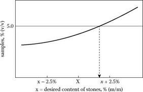
9. Design this coarse aggregate content (directly or through an interpolation of results, see Figure 7.14) so that the content of air voids is in accordance with the requirements presented next.

10. Estimate the FRs ratio for the design mix.

image76

FIGURE 7.14 Example of the design coarse-aggregate fraction content based on the content of voids; x = desired content of stones, % (m/m). (From Voskuilen, J. L.M., Ideas for a volumetric mix design method for Stone Mastic Asphalt. Proceedings of the 6th International Conference Durable and Safe Road Pavements, Kielce [Poland], 2000. With permission.)

The requirements for air voids in compacted SMA 0/11 samples, applied in the Netherlands, are as follows:

• Type 1—for low-volume traffic

• Marshall hammer 2 x 50: 4.0% air voids

• Gyratory compactor: 3.0% air voids

• Type 2—for heavy traffic

• Marshall hammer 2 x 50: 5.0% air voids

• Gyratory compactor: 4.0% air voids

Note: the relationship between air voids obtained from the Marshall method (an impact method) and those obtained from a gyratory compactor should not be interpreted as the difference -1%, because the air void content obtained in samples from the gyratory compactor largely depends on the adopted number of rotations and the angle of rotation of the gyratory compactor. Therefore air void content is not the same in every case.

Context

Roads and road traffic influence the natural environment in a complex manner. At the same time as roads serve the transport of people and goods, roads take land and form barriers to the movement of people, animals and water in the land­scape. A range of pollutants is emitted from roads and traffic and spread to the environment.

The pollutants are transferred away from the road mainly via road-surface runoff and aerial transport but also with percolation through the pavement. Runoff pol­lution is a much studied issue whereas much less is known about pollutants per­colating through the pavement and embankment into the groundwater and surface waters.

The vast majority of the pollutants stay close to the road where they accumu­late in vegetation, soil and also animals. To some extent, pollutants are transported further away mainly by aerial transport but also by water movement. In ecosys­tems receiving traffic pollutants, various ecosystem compartments and ecological processes will be affected.

Context

Water is one of the most important transport media for the pollutants. Soil and water are the main targets of the pollutants (Fig. 6.1). Man, animals and plants are dependent on water of good quality, and legislation typically puts much emphasis on the protection of groundwater and surface water. Given the dense road network and rapidly increasing traffic, protecting the environment from road and traffic pollutants and securing a good water quality is an area of increasing concern to road planners and engineers.

Fig. 6.1 Sources and routes of contaminants in the road environment. Reproduced by permission of the Swedish Road Administration

This chapter is devoted to sources, transport pathways and targets of road and traffic pollutants, as introduced in Chapter 1 (see Section 1.6 and Fig. 1.7). The domain dealt with is confined to the area vertically limited by the pavement surface and the groundwater table, and laterally by the outer drainage ditch at each side of the road (see Fig. 2.1). Pollutant sources such as traffic, cargoes, pavement and maintenance are briefly described. Knowledge of pathways and trans­port processes is important for the understanding of pollutant appearance in sat­urated or unsaturated porous media, and consequently for the understanding of effects on ecosystems and their compartments. Following a discussion of these issues, a concluding section briefly refers to EU legislation pertaining to the pro­tection of waters as a natural resource, and the role of roads and traffic in that connection.

Cob and Other Wet Clay Techniques

Throughout history, several methods for mud construction have evolved using wet mud fashioned into various shapes and stacked onto the wall while still plastic. The mud is then fused with the layers below it to create a monolithic wall. This type of construction has lent itself to laybuilders because it requires no formwork or special equipment and no pro­cessing other than onsite mixing. Two mod­ern innovations in this building method are of note.

In Germany, Gernot Minke has devel­oped a method called stranglehm for build­ing with extruded clay profiles. Casein or whey is added to the clay mixture to make the clay more water resistant. Minke has created a mechanized extrusion apparatus for use at the building site that can produce about six feet of material per minute. The uniformly extruded profiles, which are three by six inches and just over two feet long, are stacked one on top of another and pressed to adhere to the layer be­low. Construction joints are placed vertically between the ribbons and “caulked” with a mud mixture after the ribbons are dry so that shrinkage is controlled and air infiltration can be blocked. Being used as infill between wooden structural members, the system is not load bearing. Insulation must be added to the exterior in colder climates.

In North America, the Cob Cottage Com­pany has been responsible for the revival of cob, or wet mud, construction. Founders Ianto Evans, Linda Smiley, and Michael Smith have developed a stronger mix using a more con­trolled formulation process than their pre­decessors did. The Oregon Cob method that they have developed is characterized by small, free-flowing, sculpturally shaped homes with arched windows and doors and a strong solar orientation. Their designs emphasize maxi­mum space utilization through curvilinear

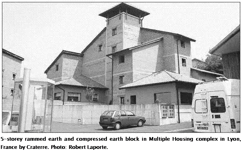
Подпись: 5-storey rammed earth and compressed earth block in Multiple Housing complex in Lyon, France by Craterre. Photo: Robert Laporte.

formations and built-in benches and plat­forms. In England, this traditional form of building has been revived by Katy Bryce and Adam Weismann of Cob in Cornwall Ltd.

Cob construction uses moistened earth containing suitable clay and sand content that is mixed with straw and formed into stiff loaves of a size that can be moved, person to person, from the mix site to the building site. The loaves are then piled onto a wall and blended with the previous layers. The result is a monolithic, load-bearing mud wall.

Cob has R-values comparable to adobe construction and is best suited to warmer cli­mates where less insulation is required and high thermal mass is effective. Cob is also valuable for adding thermal mass in the inte­rior of buildings, especially for heat storage in passive solar designs. Anecdotal evidence has indicated that it exhibits better seismic per­formance than adobe because the walls are monolithic.5


Rammed Earth

Historically, rammed earth construction has been found not only in hot, arid climates but also throughout the cold, wet regions of Eu­rope. Thousands of rammed earth structures, some dating back 400 years, can be found in the Rhone River valley.

Earth with the proper moisture, sand, gravel, and clay content is rammed into form­work in six – to eight-inch layers. When form­work is full it can be immediately removed and reused for the next sector of wall. Because of the low moisture content, the walls, if prop­erly constructed, will not shrink or crack. No curing time is required and construction can continue without any delay in sequencing.

The finished walls are thick, precise, and beautiful. Different colors of earth can be used to create decorative effects. Rammed earth walls are usually left exposed without any further finishing. Unlike adobe or stone masonry, where the joints are pathways for

Подпись: Rammed Earth or "pise" multi-storey housing complex by Craterre in Lyon, France. Photo: Robert Laporte.

erosion caused by the expansion of water, the monolithic surface of rammed earth has proven to hold up extremely well to freeze and thaw cycles. With modern comfort and en­ergy demands, this technique is most suitable in warmer climates. However, innovations, such as placing a two-inch board of rigid insu­lation at the center of the wall, have been used to adapt this method for cold climate use.

Of all the earth building techniques de­scribed in this chapter, rammed earth tech­nology has advanced the most through the use of modernized machinery. It has been cal­culated that historic homes of rammed earth took as many as 30 worker-hours per cubic meter of wall construction, whereas highly mechanized techniques can take as few as two worker-hours per cubic meter of wall.6 Ad­aptation to mechanization, improvements in formwork, high compressive strength, and short curing time make this type of earth con­struction suitable for large projects. Highly re­
fined, multistory buildings have been created using this technique, including the five-star Kooralbyn Hotel and Resort in Australia.

With more test data being accumulated in both the US and Europe on the structural properties of rammed earth, it is becoming easier for professional engineers to create re­liable structural designs and predict how the material will act under extreme conditions. In earthquake zones, some concrete has been added to the mix, and steel reinforcement has been used in much the same way as in concrete structures, allowing permits to be granted throughout earthquake-prone Cali­fornia, where David Easton, a pioneer and in­novator in the rammed earth revival, lives and works.

DECK SURFACES AND DECK OVERLAYS

New Construction. Some agencies use asphalt concrete overlays on new decks and protect the deck with a waterproofing membrane below the asphalt overlay. Currently, however, concrete-wearing surfaces are more popular on new bridges than asphalt concrete. Concrete surfaces may be placed as an integral part of the structural bridge deck (monolithic), or placed as bonded overlays of various types including dense concrete, latex-modified concrete, and silica fume concrete (see Art. 4.5.1).

Repair of Existing Bridge Deck Surface. The concrete overlays discussed above can be used, in combination with patching of spalled areas, as a means of repairing deteriorated existing bridge decks. In addition to these overlays, which are at least 1/4 in (32 mm) thick and usually thicker, thin overlays 1/2 in (13 mm) or less thick are available. Binder materials include epoxy, epoxy-urethane blends, and polyester resin. Because of their thinness and light weight, they are advantageous for bridges where weight reduction is desirable, or where thicker overlays would present problems with expansion joint or scupper modification, or where railing height would be reduced more than an acceptable amount by a thicker overlay. In recent years use of methyl methacrylate (MMA)-type material has gained popularity due to its waterproofing properties coupled with extremely high strength and chemical resistance with an abrasion-resistant surface.

The repair of a spalled bridge deck involves removal of the fractured or disintegrated concrete by some means. Mechanical methods include scabblers, scarifiers, and jackhammers. Because these methods all tend to create microfractures in the sound concrete, a better method is hydroblasting, or use of very high pressure water jets. This method is selective in that it automatically removes unsound concrete while leaving the sound concrete undamaged. The operation consumes large quantities of water and is noisy, and passing motorists must be protected from stray jets and flying debris. The muddy effluent must be disposed of properly, and not allowed to flow into catch basins.

After removal of unsound concrete, or concurrently with it, the surface of the remaining good concrete is removed to a depth of about 1/4 in (6.4 mm). The entire surface to be over­laid is dried or wetted to the required moisture condition, and the overlay placed. Where deep removal areas are present, it is generally preferable to patch these areas in a separate operation from the general overlay. After texture is applied, the fresh overlay concrete is then given an appropriate cure of the required duration. In cold weather the overlay must be prevented from freezing. For this reason specifications require placement at temperatures well above freezing.

Raise exterior butt walls next

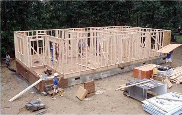
Once you’ve finished with the exterior through walls, it’s time to raise the exterior butt walls. Remember that you want the butt walls’ double top plates to be about 3/4 in. longer than the top plates (5/4 in. for 2×6 walls) so that they will lap over the through walls’ top plates. This can make it difficult to raise the butt walls, though, because the double top plate sticks out at both ends.

There are a couple of tricks for making it easier to raise these and other butt walls. One approach is to double-plate the entire butt wall except for a short section—say, 4 ft. or 5 ft.—at each end. Cut these short pieces and tack them to the wall to keep them close at hand (see the bottom right photo on p. 103). Then nail them on after raising the wall. Alternatively, you can leave off a section of the double top plate from one end of the wall, then jockey the opposite end into position with a couple of helpers. With a little experience, you’ll learn these shortcuts.

Raise exterior butt walls nextWhen the last wall has been raised, something special happens. What was once just a jumble of fram­ing lumber on the deck all of a sudden feels like a house with real rooms.

Raise exterior butt walls nextRaise interior walls from the longest to the shortest

As you raise and position each wall, nail the end stud of each intersecting butt wall flush with the corner or channel on the through wall. Use three 16d nails: one 2 ft. up from the bottom, one 2 ft. down from the top, and one in the center. After all the walls are raised, stop and admire your work. It’s like magic: As you stand in individual rooms, you can see the shape of the house.

Tie off the double top plates

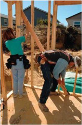
Nailing the lapped double plate into the adjoining top plates ties the entire framed structure together. This important task, when done accurately, makes it easy to plumb and straighten the walls. If you are a gymnast, like my carpenter-daughter, you can hop right up on the plates and start tying the walls together. Otherwise, it’s best to work on a sturdy ladder.

The corner marks you drew on the plates earlier now serve as guides when nailing off the top plates. Make sure that the double top plate is on these lines and that the top plates of both walls are touching. If necessary, toenail a 16d nail up through the top plate of the through wall into the double top plate ol the butt wall to draw everything together, as shown in the bottom right photo. Nail two 16d nails through the lap into the intersecting wall.

STEP 7 PLUMB AND LINE THE WALLS

Подпись:Подпись: If you're nimble, you can perch on top of the framing to hammer overlapping joints together. Otherwise, do the job on a ladder. It's good practice to drive a toenail (or two) into the overlapping plate. A toenail pulls the joining walls together before the top is nailed off. The word “plumbing,” when used in the context of framing a house, means making sure that the walls are standing straight up and down. “Lining” means straightening the top plate along the length of each wall. It’s impor­tant that all the walls are plumbed and lined accurately. Anything else is unacceptable. Badly plumbed or crooked walls cause significant problems later—cabinets won’t fit properly, doors won’t close correctly, and finished surfaces

Подпись: Most walls can be held plumb and straight using 2x4 studs. Properly placed and nailed, a stud, rather than a longer piece of plate stock, will hold a wall in its proper position.

Raise exterior butt walls next

While one person holds the level, another person can nudge the wall to get it plumb, then nail off a diagonal brace to keep it that way. [Photo by Don Charles Blom]

(both inside and outside) will be wavy.

If the exterior walls were squared and sheathed before being raised, they should be plumb. Otherwise, plumb them now that they are upright. To test for plumb, use an accurate level that is at least 4 ft. long or make a plumb stick, as shown in the sidebar on the facing page. Plumbing a wall is best done with two people: one to hold the level and one to move the wall and nail off the bracing.

EXAMPLES FROM THE DEMONSTRATION PROJECTS

Подпись: JVAH Walls and PartitionsMost JVAH sites used some aspects of Optimum Value Engineered wall systems to minimize costs. The most commonly used techniques were in-line framing with 24-inch stud spacing, single top-plates, 1×4 bottom plates, two-stud outside corners, metal drywall clips instead of wall and ceiling nailers, and elimination of headers and jack studs in nonbearing walls.

Подпись: Christian County, Kentucky

Besides using OVE techniques which saved $448 per unit, Pup Robertson saved 3,000 bricks per house by starting the brick at the bottom of the wood floor instead of below grade, eliminating gable brick and reducing the wall height to 7’6"; moreover, since each house required less brick than normal, he was often able to buy odd-lot quantities at substantial savings. These techniques saved $1,685 per unit on brick veneer.

EXAMPLES FROM THE DEMONSTRATION PROJECTS

Подпись: Fairbanks, AlaskaTom Webb used 2×6 exterior walls and 2×4 interior partitions on 24-inch centers. Costs were reduced by over $1,200 per unit.

Подпись: White Marsh, MarylandRyland Homes has been using efficient construction techniques for years. For the JVAH demonstration, modular housing units were used with 24-inch on-center wall framing, two-stud corners, and no headers in nonbearing walls. Costs were reduced by $850 when compared with more typically used 16-inch on-center framing.

Подпись: Charlotte, North CarolinaJohn Crosland had already adopted most of the OVE techniques. In addition to 24-inch on-center wall framing, he also used sections of plywood truss floor joists for window and door headers. This not only was less expensive than typical built-up wood headers, but also provided space for insulation.

Подпись: Lacey, WashingtonEXAMPLES FROM THE DEMONSTRATION PROJECTS

John Phillips used almost all of the OVE framing techniques in the demon­stration homes. He also had a very innovative floor system (see floor framing section) and used single-layer plywood siding without a separate sheathing. He saved almost $1,200 per unit.

EXAMPLES FROM THE DEMONSTRATION PROJECTS

Phil Hamby reduced costs by $425 by using OVE framing techniques and single-layer plywood siding in his JVAH demonstration.


Knox County, Tennessee


Knoell Homes built exterior walls on 16-inch instead of 24-inch centers because the single-layer hardboard siding used required 16-inch stud spacing. However, most other OVE techniques (two-stud corners, elimi­nation of partition posts, no headers over openings in nonbearing walls, elimination of soffits over kitchen cabinets, etc.) were used.


Phoenix, Arizona


Chapman homes built exterior walls with 2×6 studs, 24 inches on center. He also used most other OVE tech­niques, including single-layer plywood siding. Exterior wall framing costs


Santa Fe, New Mexico


EXAMPLES FROM THE DEMONSTRATION PROJECTS

Подпись:

were about the same as conventional 2×4,16-inch on-center costs. But in order to get the same insulation R­value (R-19) with a 2×4 wall, costs would have been $460 per unit higher. Interior partition costs were reduced by over $200 per unit by use of OVE techniques.

Подпись: їїПодпись:EXAMPLES FROM THE DEMONSTRATION PROJECTS

235 * aAfjhadt akingdea З/a’c-D |?Sy. Aheath. i.n<

Ґ* or

jjOJcia 3/e“C-D pfiq.

4

і"х4’Чл. ілп

totuAH. Ill рйц. aiding

By using OVE techniques, Rex Rogers saved $495 per unit even though he used 2×6 exterior wall construction instead of the more typical 2×4,16- inch on-center construction. He had been using OVE for years and has one of the most efficient framing layouts observed in the JVAH program.

2”x6“- 24“ o. c.

Й-І9 loadt
inanfiation

273" imtham


nominad З’ьіаЬ on. compactid лапd –


concAetfL ЬлісЬл.- f, inuK укаАя.-^


‘”4miS. paiij’.” m iit une. bantiA

4" лід id po£g – лідЛйуіс bfioed


EXAMPLES FROM THE DEMONSTRATION PROJECTS

EXAMPLES FROM THE DEMONSTRATION PROJECTS

Valdosta, Georgia

Gary Minchew has long been a propo­nent of the OVE framing system. His detailed cost recording system pro­vided a unique breakdown of where costs were saved with OVE. Total reduction amounted to over $1,200 per unit when compared with conventional construction in the area.

Tulsa, Oklahoma

Wayne Hood used 24-inch on-center framing with two-stud corners on all nonbearing walls and partitions, saving $250 per unit.

Burlington, Vermont

Bill Hauke had been using OVE techniques in Vermont for years. He estimated that these methods saved him over $450 per unit in the JVAH In-fill Demonstration Project.

Mesa County, Colorado

Roger Ladd used two-stud corners and single-layer plywood siding on 16- inches on-center exterior walls. Partitions and common walls were framed 24 inches on center.

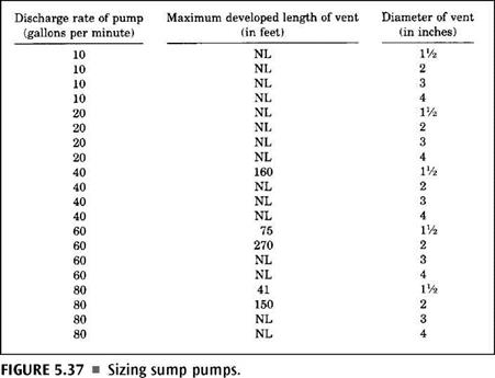
SUMP VENTS

Sump vents, the ones used to vent a sump system, are calculated on a basis of a pump’s discharge capacity. Tables are often provided for this type of sizing. See Figure 5.37 for an example of such a table. Using a table like this one, you can quickly and easily size a vent for a sump. As long as you know the discharge rate of the pump being used in the sump, the rest of the work is simple.

SUMP VENTS

SUMP VENTS