Preventing Condensation

The only other special building consideration, after the foundation and bra­cing, for a little house on wheels is condensation. Unless they are insulated, sealed, and vented properly, small spaces are prone to a lot of condensation. It simply takes less time to fill the air in a small enclosure with the moisture caused by bathing, breathing, laundry, and cooking than it does to fill a large one. If that warm, moist air comes into contact with a sufficiently cold surface, it will condense into water. That is the reason that cars come equipped with defrosters, and that small houses need to be equipped with the right insula­tion, vapor retarders, and ventilation.

I used expanded polystyrene foam board as insulation with expanding spray foam in the seams for two basic reasons: 1) It takes a thicker piece of fiber­glass batting to get the same amount of insulating power as you get out of a piece of extruded polystyrene. As I didn’t have enough space for eight-inch – thick walls, this would have stood as reason enough for my choice. 2) Foam board is far more resistant to condensation.

With fiberglass batting and other porous insulations, you have to worry about moist air getting into it and condensing when the moisture gets to the cold part of the wall. At that point, the fluffy, pink stuff turns to mush, and mush doesn’t insulate. It rots. To prevent this, you have to use a vapor retarder. This is usually just a large sheet of six-millimeter plastic hung over the inside

surface of the batting and sealed at its edges. If your seals hold and your plastic does not rip, your fiberglass should stay fairly dry.

Expanded polystyrene with an impermeable coating does not need a vapor retarder. Being virtually waterproof makes it its own retarder. I chose the white, expanded polystyrene over the pink, extruded poly because, while I love the pink stuff for its superior insulating qualities, bugs love it, too.

The threat of condensation is also what prompted me to use double-glazed, insulated windows. The glass panes on a little abode can fog up pretty quick­ly unless they are well protected against the cold. I’ve found that windows sold with gas between the interior and exterior panes work pretty well for this purpose.

The other primary way to eliminate condensation in a small enclosure is by venting it. I installed a fan at the peak of my loft. It sucks moisture-laden air out of my living quarters when I am cooking or bathing and helps keep the place cool during the summer. On cold days, the vent can be sealed with a plug I cut from some leftover scraps of foam board.

The Greek world in the classical age

With the disappearance of the Mycenaen civilization, Greece enters its dark age. For no less than four centuries writing is forgotten, not to be rediscovered until the 7th century BC with the adoption of the Phoenician alphabet of the 10th century BC. In the 5th cen­tury BC, Greek history is punctuated by the revolts of the Ionian cities against the yoke of the Persian Achaeminides; then by the Median wars with two Persian invasions in continental Greece; then by internal struggles (the Peloponnesian war). Travelers, sometimes imbued with a sense of Hellenic superiority, but also sometimes remarkably open and observing like Herodotus, open the eyes of the Greeks to Egypt and the Orient.

These “tourists” were not all peaceful; Xenophon and the successful of the Ten Thousand may have inspired the subsequent invasion of Alexander. These centuries also witness the expansion of the Greeks toward the west, with the founding of Marseilles (about 600 BC) and with the founding of Greek colonies in Sicily and the south of Italy toward the end of the 5th century BC. This expansion formed a cultural ensemble today called greater Greece.

REMOVING DOORS AND TRIM

Doors, hardware, and trim (casing) make a house distinctive. Remove and store them till you are done with tearout and rough framing. Remove doors and hardware worth saving and clearly mark them “Salvage” so they don’t get tossed. Most of the time, it’s easy to pop hinge pins and lift doors out of the frame. But if that’s not possi­ble and hinge leaves are encrusted with paint, use an old screwdriver or a chisel good for little else to chip away paint from the screw heads. Or apply paint stripper.

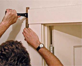
To gently remove trim, first run a stiff putty knife between the frame and the trim to break the paint seal. Don’t use anything with a sharp blade, because a sharp blade will slice into the trim. Then gently tap a flat 8-in. prybar behind the trim, as shown in the photo below, preferably near the nails holding it down. Pry up along the entire length of the trim, raising it little by little. Be patient. As you remove trim pieces, use a per­manent marker to number the back of each so you can reinstall trim assemblies correctly.

REMOVING PLASTER AND DRYWALL

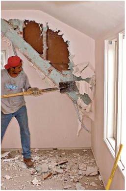
Whether you’re cutting a large hole for a skylight or gutting the whole ceiling, try to minimize the mess. Using a reciprocating saw with a demo blade to cut out 2-ft. by 2-ft. sections of drywall or plaster, you’ll create a lot less dust and have a compact load to carry to the trash. But that’s not always possible.

If the old plaster falls off the lath as you try to cut out sections, go ahead and break it out. Pull the lath and plaster down together, using a pick or crowbar, or use a hand sledge or a 2×4 to pound it down from the attic space above (place planks across the attic joists) or from the back side of the wall, if it’s exposed. After separating and bundling the lath, shovel the plaster into buckets.

Dress for the job: hard hat, goggles, dust mask, heavy gloves, long-sleeved shirt. Wear thick-soled work boots when gutting plaster:

Lath nails are ubiquitous and razor sharp, and they’ll puncture tennis shoes in a flash.

Ceilings. О If ceiling joists are exposed in the attic, first take out the insulation from the area to be removed. If it’s loose insulation, use a dustpan to shovel it into a garbage bag.

If you work on the ceiling from below, use movable scaffolding for ceilings 10 ft. or higher. Otherwise stand on 2-in.-thick planks straddling sawhorses or stepladders. If the plaster is solidly adhered to the lath, use a reciprocating saw to “outline” sections. Then rock them from side to side till the nails holding them to joists work free. Hand the removed section to a helper on the floor. Then proceed to the next plaster section.

If plaster is sound but sagging in a few spots, you may be able to reattach it with washered screws or cover it with 14-in. drywall, as described in “Attaching Top Plates,” on p. 166.

Walls. О Walls are easier to gut than ceilings because debris won’t rain on you. Start at the top of each wall and work down, periodically carting out debris before it restricts your movements. Again, use a recip­rocating saw to cut out 2-ft.-sq. sections if possible; otherwise break them out. Tile walls, you’ll need to break out. If you’ll be putting up new drywall or plaster, this is the time to pull old nails. Likewise, remove any old wires and pipes.

Подпись: A skillful integration of old and new framing: After stripping interior surfaces and removing a wall to enlarge the room, carpenters installed a new 4x4 window king post and a third top plate to raise the old wall's framing. WoterOld and new window headers line up.
image344

Before removing bearing walls, first shore up the joists or other loads they support. But if you’re removing a nonbearing partition, you can do so after stripping plaster or drywall. Cut through the middle of each stud, using a recipro­cating saw; its thin blade is less likely to bind than a circular saw’s. With studs cut, pull them away from their plates. To remove plates, pry them up with a wrecking bar (goggles and a hard hat are musts). Use a metal-cutting blade in a reciprocating saw to cut through any remaining nail shanks.

REMOVING WOOD FLOORING

If they’re solidly attached, old wood floors are generally left in place, to be refinished later or floored over. However, it’s sometimes necessary to pull up a few boards so you can install joists or blocking, run wires, or patch-repair floor sections elsewhere. Partitions installed over finish floor­ing make it difficult to pry out floorboards.

If you’ll be reinstalling the floorboards, try to pry them up in an inconspicuous spot, such as along the base of an existing wall. Remove the baseboard trim and try to insert a flat bar under the leading edge of a floorboard. You may need to destroy the first row of boards to get them out if they’re face-nailed or, at the very least, break off the tongue on tongue-and-groove flooring. Successive courses will likely be toenailed through the tongue.

If you’re gutting wall surfaces, the space between studs is a good place to fit the curved head of a wrecking bar, to pry up a first row of floorboards.

Reinforcing and Repairing the Structure

This section focuses on upgrading nonbearing structural elements: adding blocking, leveling ceil­ings, straightening stud walls, bolstering joists, and treating rotten or insect-damaged wood.

ADDING BLOCKING

In renovation, it’s common to add blocking (short pieces of wood) to bolster existing joists or studs, to give new framing something to nail to, and to provide backing for the drywall or plaster lath to come.

Attaching top plates. To attach the top plate of a new partition, first cut back finish surfaces to expose ceiling joists. Snap two parallel chalklines to indicate the width of the top plate. If joists run perpendicular to the partition, cut out a 4-in.- wide slot to receive the top plate. Remove plaster or drywall sections, relocate insulation (if any), and pull nails sticking out of the joists. Use a util­ity knife to clean up ragged edges before nailing up the top plate, using two 16d nails at each point the plate crosses a joist.

If joists run parallel to the partition, cut back finish surfaces to joist centers on either side of the proposed plate so you can add blocking.

Snap chalklines to indicate joist centers, and cut along those lines. (Set a plaster-cutting circular – saw blade to the thickness of the ceiling drywall or plaster. Wear eye protection.) Install blocking that’s the same depth as the joists, spaced 24 in. on center. Cut blocking square for a tight fit, and make sure that its lower edges are flush to the

underside of the joists. If there’s access, end-nail each block with three 12d nails, through adja­cent joists. If you toenail them, use four 8d nails on each end. A pneumatic palm nailer is ideal for driving nails in such tight spaces.

Finally, add backing for the ceiling patch to come and reattach plaster or drywall edges along joist centers, as needed. Metal drywall clips (see the photo on p. 360) are a good alter­native to blocking. Nail them to the top edge of the top plate.

Blocking for walls. (^) To effectively nail off a new wall where it abuts an existing one, first cut into the existing wall to expose the framing. Start with a small exploratory hole to determine exact­ly where the studs are. Then cut back finish sur­faces to the nearest stud center on either side.

Even if your new wall runs directly to a stud in place, add blocking for metal drywall clips to reattach drywall patches.

If, as is more likely the case, there are no studs in the spot where you need a nail off, add them, as shown in the drawing "Where Walls Meet,” at right. These nailers will be stronger if you preassemble them and then sledge them into place. Face-nail them together with 16d nails staggered every 16 in. Full-length nailers should be toenailed with three 10d or four 8d common nails top and bottom. Or prenail metal L-angles to tie nailers to plates.

Blocking for sole plates. Nail partition sole plates to the framing below, not merely to floor­ing or subflooring. If the partition runs perpendi­cular to the joists, use two 16d nails at each point the sole plate crosses a joist. (See p. 169.)

However, if the wall is parallel to the joist grid, try to locate it over an existing joist. If that’s not possible, add blocking between the joists so there’s something solid to nail the sole plate to.

If the partition is nonbearing, use blocking the same depth as the joists, spaced on edge every 24 in. on center. Cut the blocking square so that it fits snug, flush to the underside of the subfloor­ing. Use two or three 16d common nails to end – nail blocking through the joists. Blunt the nail points to prevent splits.

Note: Bearing walls should be supported by two full-length joists, on edge, running directly under the sole plate. Add blocking to adjacent joists to keep the new joists from rotating, and attach both ends with a double-joist hanger. Because doubled joists are, in effect, a girder, they may also need post support beneath; see "Beam Span Comparison,” on p. 213, which offers sizes and spans. But because local codes have the final say, consult a structural engineer in your area.

Design Considerations for Rafters and Girders

As we have seen, the posts and the planks are the strong components of the post and beam (post and girder) and plank and beam (plank and joist or rafter) systems. The use of posts in scale with the girders will assure post strength. Two – by-six tongue-in-groove planking is an excellent and pleasing floor and roof system, although you should know that the true finished dimensions of this material is actually 1.V2 inches thick by about 5Vs inches wide. With frequent joists or rafters, you can easily use the lighter and less expensive “five-quarter” (full one – inch) by six-inch (<yV8 inch) tongue-in-groove planking. In reality, you can use three-quarter-inch plywood, even with an earth roof, as we did at our library. We had no sagging at all, though the greatest span on the radial rafter system was only about 39 inches (99 centimeters), and this was on the overhang.

The members that need to be engineered for are the girders, the rafters, and the floor joists. It is important to know that there are five distinct considerations that come into the design work for these members, and they are:

i. Load. You have to know what degree of load you are asking the system to support. (See Sidebar on page 31.) So, as an example, if you are planning an eight-inch-thick thick earth roof over a two-inch-thick crushed stone drainage layer, for an area with a 70-pound snow load, add the following figures from the chart: 80 (earth) + 20 (stone) + 70 (snow) + 15 (dead load) = 185 PSF.

2. Wood quality. To engineer for any beam, you have to know the stress load values for the species and grade of wood you plan to use, particularly the unit stress ratings for bending and for shear (in pounds per square inch). For example, unit stress for bending can vary from 1,100 PSI (Eastern Hemlock, common structural) to 2,150 PSI (Douglas Fir, inland region, select structural).

3. Frequency of rafters or joists. As discussed above, under the heading Plank and Beam (page 29), frequency simply refers to how many members you are using. Are the rafters on 16-inch centers? 24-inch centers?

4. Beam dimensions in section. Will you be using two-by-eights? Five-by – tens? Eight-by-eights? Vigas with a small-end diameter of six inches?

5. Clear span of the beam. This is the one that trips up most owner-builders, particularly when it comes to designing a structure to support an earth roof.

The problem is that bending strength decreases as the square of the span.

For example, lets compare a io-foot span to a 20-foot span. Instinctively, many people think that a beam has to be twice as strong to support the longer span, other considerations remaining the same. There’s a kind of logic there, but it is wrong. You’ve got to compare the squared spans. Ten times ten equals one hundred (10 X 10 = 100), but twenty times twenty equals four hundred (20 X 20 = 400). The beam carrying the 20-foot span needs to be four times stronger than the one carrying the io-foot span.

I’m going to give another less obvious example of how span (squared) influences strength, an example that pops up all the time with students at our earth-sheltered housing classes. The stress-load calculations for both the Earth wood house and the “40 by 40 Log End Cave” plans are predicated upon

nine-foot spans. These are popular designs that have been built all over North America. Invariably, people ask me if they can stretch the spans to ten feet. (Nine feet, 1 guess, seems just a little tight for them.) The answer is, of course, yes, you can do almost anything if you know what you’re doing and you have enough money. Instinctively, people figure that rafters or girders probably have to be io percent stronger to carry the extra foot of span. The math says otherwise: 9X9 = 81. But 10 X 10 = 100. The difference is 19. And this difference must be expressed in relationship to the original 81, not 100. Well, my trusty calculator tells me that 19/81 = .23457. The change will require making up a shortfall of about 23.5 percent, a considerable difference from the original engineering.

In the example above, the span has been changed, so one or more of the other four design considerations must be altered to make things right. We could decrease the load by 23.5 percent by using less earth and using a lightweight drainage product instead of a crushed stone drainage layer… or by building in Chattanooga instead of Buffalo to take advantage of the decreased snow load. We could choose a wood with 23.5 percent more bending strength, perhaps a stronger species or a higher grade of the same species. We could actually use 23.5 percent more of the originally engineered rafters by increasing the frequency, and that would take care of it. Or we could reengineer the sectional dimensions of the rafter; use six-by-tens instead of five-by-tens, for example.

You must know four of the five variables listed above to calculate the fifth. If you know load, quality of wood, rafter frequency, and span, for example, you can calculate the cross-sectional dimensions of the rafter. Or, given the kind and grade of wood, you can calculate the load that a particular rafter system will support.

If you can plug numbers into a formula, you may wish to follow through the examples of Appendix B: Stress Load Calculations for Shear and Bending. But, in reality, for more conventional (non-earth) roof systems, just use existing engineered span tables, like the one in Appendix A.

Estimation of Distributional Parameters

For a chosen distributional model, its shape and position are completely defined by the associated parameters. By referring to Eq. (3.5), determination of the quantile also requires knowing the values of the parameters в.

There are several methods for estimating the parameters of a distribution model on the basis of available data. In frequency analysis, the commonly used parameter-estimation procedures are the method of maximum likelihood and the methods of moments (Kite, 1988; Haan, 1977). Other methods, such as method of maximum entropy (Li et al., 1986), have been applied.

3.6.1 Maximum-likelihood (ML) method

This method determines the values of parameters of a distribution model that maximizes the likelihood of the sample data at hand. For a sample of n indepen­dent random observations, x = (x1, x2,…, xn)1, from an identical distribution, that is,

Xi ~ fx(x | в) for i = 1,2,…, n

in which в = (0i, 02,…, 6m) a vector of m distribution model parameters, the likelihood of occurrence of the samples is equal to the joint probability

of {xi}i=1,2,…,n calculable by

n

L(x | в) = Ц fx(xi | в) (3.10)

i=1

in which L(x |в) is called the likelihood function. The ML method determines the distribution parameters by solving

Max L(x | в) = maxln[L(x | в)]

в в

or more specifically

nn

Подпись: (3.11)Maxll fx(Xi | в) = ln[fx(Xi | в)]

i=1 i=1

Estimation of Distributional Parameters
Подпись: Example 3.4 Referring to Eq. (2.79) for the exponential distribution as
Подпись: fx(x | в) = exp(-x/в)/в for x > 0, в > 0 determine the maximum likelihood estimate for в based on n independent random samples {xi }i=1,2,..., n Solution The log-likelihood function for the exponential distribution is

As can be seen, solving for distribution-model parameters by the ML principle is an unconstrained optimization problem. The unknown model parameters can be obtained by solving the following necessary conditions for the maximum:

Подпись: i=1

which is the sample mean.

Подпись: fx(x | а, в) = Подпись: 1 Подпись: _ 1 / x-а  2 PH в ) Подпись: for — 00 < x <00

Example 3.5 Consider a set of n independent samples, x = (xi, x%,…, xn)1, from a normal distribution with the following PDF:

Determine the ML estimators for the parameters a and в.

Подпись: L(x | а, в) = Estimation of Distributional Parameters Estimation of Distributional Parameters

Solution The likelihood function for the n independent normal samples is

Подпись:n, Y^n=1(xi – a)2

2в2

Estimation of Distributional Parameters Estimation of Distributional Parameters

Taking the partial derivatives of the preceding log-likelihood function with respect to a and в2 and setting them equal to zero results in

After some algebraic manipulations, one can easily obtain the ML estimates of normal distribution parameters a and в as

a Ei=1 xi в2 Ei=1(xi – a)2

aML = —n~ ^L =——————- n————

As can be seen, the ML estimation of the normal parameters for a is the sample mean and for в2 is a biased variance.

3.6.2 Product-moments-based method

By the moment-based parameter-estimation methods, parameters of a distribu­tion are related to the statistical moments of the random variable. The conven­tional method of moments uses the product moments of the random variable. Example 3.3 for frequency analysis is typical of this approach. When sample data are available, sample product moments are used to solve for the model parameters. The main concern with the use of product moments is that their reliabilities owing to sampling errors deteriorate rapidly as the order of moment
increases, especially when sample size is small (see Sec. 3.1), which is often the case in many geophysical applications. Hence, in practice only, the first few statistical moments are used. Relationships between product-moments and pa­rameters of distribution models commonly used in frequency analysis are listed in Table 3.4.

3.6.3 L-moments-based method

As described in Sec. 2.4.1, the L-moments are linear combinations of order statistics (Hosking, 1986). In theory, the estimators of L-moments are less sen­sitive to the presence of outliers in the sample and hence are more robust than the conventional product moments. Furthermore, estimators of L-moments are less biased and approach the asymptotic normal distributions more rapidly and closely. Hosking (1986) shows that parameter estimates from the L-moments are sometimes more accurate in small samples than are the maximum – likelihood estimates.

To calculate sample L-moments, one can refer to the probability-weighted moments as

вr = M1,r, o = E{X[Fx(X)]r} for r = 0,1,… (3.13)

which is defined on the basis of nonexceedance probability or CDF. The esti­mation of вг then is hinged on how Fx(X) is estimated on the basis of sample data.

Consider n independent samples arranged in ascending order as X(n) < X(n-1) < ■ ■ ■ < X(2) < X(1). The estimator for Fx(X(m>) for the mth – order statistic can use an appropriate plotting-position formula as shown in Table 3.2, that is,

m ___ a

F( X (m)) = 1———————- —— T for m = 1,2,…, n

n + 1 – b

with а > 0 and b > 0. The Weibull plotting-position formula (a = 0, b = 0) is a probability-unbiased estimator of Fx(X(m>). Hosking et al. (1985a, 1985b) show that a smaller mean square error in the quantile estimate can be achieved by using a biased plotting-position formula with a = 0.35 and b = 1. According to the definition of the в-moment вг in Eq. (3.13), its sample estimate br can be obtained easily as

1n

br = – J^X(m)[F (X(m))]r for Г = 0,1, … (3.14)

П i=1

Stedinger et al. (1993) recommend the use of the quantile-unbiased estimator of Fx(X(m)) for calculating the L-moment ratios in at-site and regional frequency analyses.

Distribution


Estimation of Distributional Parameters

Range


Product moments


L-Moments


*1 — M; *2 — O/

тз — 0;Т4 — 0.1226


Normal


— Ж < x < Ж


Min x — ln(Mx) x/2;

o2n x — ln(^2 +1);

Yx — 3^x +


2


1 /ln(x)-A1n x

2 V Oln x


Estimation of Distributional Parameters

Lognormal


x > 0


Eq. (2.68); Eq. (2.70)


*1 — % + aJ n / 2;

*2 — 2 а^ж(л/2 — 1) т3 — 0.1140; т4 — 0.1054


Estimation of Distributional Parameters

Rayleigh


% < x < Ж


a > 0

for в > 0: x > %; for в < 0: x < %


M — % + ав; о2 — ав2; Y — sign(в) JJS


Estimation of Distributional Parameters

Pearson 3


-(х—%)/в


*1 — в; *2 — в/2; тз — 1/3; Т4 — 1/6


Exponential fx(x) — e х/в/в


x > 0 m — в


M — % + 0.5772в; о2 — 2І6!; y — 1.1396


*1 — % + 0.5772в; *2 — в ln(2); т3 — 0.1699; т4 — 0.1504


Gumbel (EV1 fx(x) — 1 exp j — (xj^) — exp — (x^—^^ —ж < x < ж

for maxima)


M — вГ (1 + 1);

о2 — в2 [Г (l + D — г2(і + 1)]


*1 — % + вГ (1 +±);

*2 — в (1 — 2—1/рГ (1 + і)


fx (X) — a (XP)“ —1exP — ( ^


Weibull


а, в > 0; x > 0


*1 — % + (§) [1 — Г(1 + а)]; *2 — § (1 — 2—а )Г(1 + а);


а> 0: х < (% + §); а < 0: х > (% + І)


M — % + ) [1 — Г(1 + а)]; о2 — (в)2 [Г(1 + 2а) — Г2(1 + а)]


Generalized Fx (х) — exp| — (l — а{‘Х— %) ] 1/а|

extreme-value ^ *

(GEV)


2(1—3-°) 3.

(1—2—“) ’

1—5(4—“ )+10(3—“)—6(2—“)
1—2-“


тз

т4


Estimation of Distributional Parameters

а > 0:

z <х < (% +1); а < 0: Z < х < ж;


Generalized Fx (х) — 1 — (l — а (Х—%) ]1/а

Pareto (GPA)


Подпись: 123

For any distribution, the L-moments can be expressed in terms of the probability-weighted moments as shown in Eq. (2.28). To compute the sample L-moments, the sample probability-weighted moments can be obtained as

11 = 60

12 = 261 — 60

13 = 662 — 661 + 60 (3.15)

14 = 2063 — 3062 + 1261 — 60

Estimation of Distributional Parameters Подпись: t _ l3 t3 = І2 Подпись: t l4 t4 = І2 Подпись: (3.16)

where the lr s are sample estimates of the corresponding L-moments, the Xr s, respectively. Accordingly, the sample L-moment ratios can be computed as

where t2, t3, and t4 are the sample L-coefficient of variation, L-skewness co­efficient, and L-kurtosis, respectively. Relationships between L-moments and parameters of distribution models commonly used in frequency analysis are shown in the last column of Table 3.4.

Example 3.6 Referring to Example 3.3, estimate the parameters of a generalized Pareto (GPA) distribution by the L-moment method.

Solution Since the GPA is a three-parameter distribution, the calculation of the first three sample L-moments is shown in the following table:

Year

qi (ft3/s)

Ordered q(i) (ft3/s)

Rank

(i)

F (q(i)) =

(i — 0.35)/n

q(i) x F(q(i))

q(i) x F (q(i))2

q(i) x F (q(i))3

1961

390

342

1

0.0433

14.82

0.642

0.0278

1962

374

374

2

0.1100

41.14

4.525

0.4978

1963

342

390

3

0.1767

68.90

12.172

2.1504

1964

507

414

4

0.2433

100.74

24.513

5.9649

1965

596

416

5

0.3100

128.96

39.978

12.3931

1966

416

447

6

0.3767

168.37

63.419

23.8880

1967

533

505

7

0.4433

223.88

99.255

44.0030

1968

505

505

8

0.5100

257.55

131.351

66.9888

1969

549

507

9

0.5767

292.37

168.600

97.2260

1970

414

524

10

0.6433

337.11

216.872

139.5210

1971

524

533

11

0.7100

378.43

268.685

190.7666

1972

505

543

12

0.7767

421.73

327.544

254.3922

1973

447

549

13

0.8433

462.99

390.455

329.2836

1974

543

591

14

0.9100

537.81

489.407

445.3605

1975

591

596

15

0.9767

582.09

568.511

555.2459

Sum =

7236

4016.89

2805.930

2167.710

Note that the plotting-position formula used in the preceding calculation is that pro­posed by Hosking et al. (1985a) with a = 0.35 and b = 1.

Based on Eq. (3.14), the sample estimates of Pj, for j = 0,1, 2, 3, are Ьз = 428.4, b1 = 267.80, Ьз = 187.06, and b4 = 144.51. Hence, by Eq. (3.15), the sample estimates of к j, j = 1,2, 3,4, are I1 = 482.40, I2 = 53.19, I3 = -1.99, and I4 = 9.53, and the corresponding sample L-moment ratios Tj, for j = 2, 3, 4, are t2 = 0.110, t3 = —0.037, and t4 = 0.179.

Estimation of Distributional Parameters

By referring to Table 3.4, the preceding sample h = 482.40, I2 = 53.19, and t3 = —0.037 can be used in the corresponding L-moment and parameter relations, that is,

FASTENERS AND HARDWARE

Carpenters don’t just use wood, nails, and screws for building. Many other types of metal hardware go into a house as well, and knowing what to use and when to use it can be baffling. Fortunately, most of the time we use only a few varieties on a regular basis. Here’s an overview of the basic types of hardware used by carpenters.

Nails

Nails are the most common fasteners used by carpenters because they are inexpensive and quick and easy to use.

Nail sizes When choosing nails, you have to think about the size you need, whether it’s for interior or exterior use, and how many you’ll need.

Nail sizes are dictated by the penny­weight system (abbreviated with a "d"). In general, a nail with a lower penny designation will be shorter and will have a thinner shank than a nail with a higher penny designation. For instance, an 8d nail is thinner and shorter than a 16d nail.

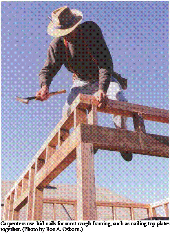
Подпись: Carpenters use 16d nails for most rough framing, such as nailing top plates together. (Photo by Roe A. Osborn.)

There’s no reason to drive larger nails than needed. I’ve seen carpenters nail doorjambs to studs with 8d nails when 6ds would have sufficed. If you are in doubt about the size nail needed, check with your building department. Many codes specify the minimum size nail needed for a particular job, how many to use, and where to drive them (this is typically called a nailing schedule).

Nails used inside the house aren’t exposed to the weather, so they usually don’t require coatings or treatment to withstand rusting. On the exterior, how­ever, nails have to stand up to whatever Mother Nature throws at them. When nailing exterior siding, for instance, use nails that won’t rust and stain the wood, like hot-dipped galvanized (zinc-coated), stainless-steel, or aluminum nails. For holding power, choose ring-shank nails (nails with ridges) or screw nails.

Nails are purchased by the pound, so carpenters typically buy large quantities to save money. It’s cheaper to buy one 50-lb. box than it would be to buy five 10-lb. sacks. A typical 1,200-sq.-ft. wood-framed house can be nailed together with about 10,000 16d nails (200 lb.) and 5,000 8d nails (50 lb.).

Types of nails The type of nail you buy depends on the job at hand, and whether you’re framing or doing finish work. The nails a carpenter uses often are designated common, box, or finish.

Common and box nails are used mainly for framing. Box nails are thinner than common nails and are preferred for framing because they’re easier to drive. Many framers use what are called sinkers, which are nails coated with resin or vinyl. These nails drive easily and have good holding power.

The two most common framing nails are 8ds {2Vi in. long) and 16ds (ЗУ2 in. long). The 8ds are used to nail sheathing to floors or walls and cripple studs to headers, for example, while 16ds are used to nail together 2x stock, such as plates to studs.

Finish nails are used to nail trim boards like door casing and baseboard. These nails have small heads and can be driven below the surface of the wood with a nailset and the holes covered with putty. There are many different finish-nail sizes,

Подпись:FASTENERS AND HARDWAREПодпись: іthe most common being 4d, 6d, and 8d. Brads are short (less than 1 in. long) fin­ish nails. If nailing trim on the exterior, use aluminum, stainless-steel, or galva­nized nails.

There are also a number of different spe­cialty nails. Double-headed (or duplex) nails are used in concrete formwork and for temporary scaffolding. The top head remains above the surface, making the nail easy to pull out. Hanger nails are short, hardened nails used to attach metal framing anchors (such as joist hangers) to wood. Masonry nails are used for nailing into concrete.

There are even plastic nails that can be used with pneumatic nailers (Utility Composites; see Sources on p. 198). Plastic nails have good holding power, won’t rust, can be cut with a saw, and can even be sanded with a belt sander.

Screws

The advent of the cordless screw gun has made screws the fastener of choice for many carpenters. Screws are used for everything from fastening sheet goods to installing trim and hardware. As with nails, don’t use a larger-size screw than you need, and if the screw is installed outside, choose a type that will stand up to the weather.

Wood screws can be used for all sorts of home-building jobs. Stores stock many types of wood screws, such as slotted, Phillips head, and square drive (see the drawing above). Standard lengths range from 1/4 in. to б in., and common gauges are 8 through 14 (the lower the gauge number, the thinner the screw shank). Head shapes are flat, round, and oval, and some are designed to be driven below the surface of the wood (called countersink heads). Most screws are made of steel, but aluminum, brass, and stainless steel are available. A standard
wood screw often requires a pilot hole so you don’t split the wood as you drive the screw.

For better or worse, drywall screws have replaced wood screws on today’s build­ing sites. Although they were originally designed just to attach drywall to wood or metal, carpenters discovered that they have other uses. They are used so often that, when people ask for screws on a job site, they are usually talking about drywall screws.

Drywall screws (sometimes called bugle – head screws) have a Phillips head, range from 3A in. to 3 in. long, and usually have a flat black finish. With their thin shanks, deep threads, and sharp points, they can often be driven without a pilot hole. Drywall screws hold well and usu­ally won’t split the wood, and their bugle-shaped, flat head countersinks itself in drywall or soft wood.

Plumb the exterior walls first

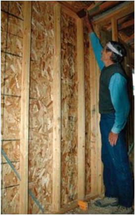
Hold a level or plumb stick in a corner to see whether the bubble is centered in the vial. If not, the wall must be moved laterally. Sometimes a wall can be moved a bit with a bodily shove. If you can push the wall plumb, install a temporary 2x diagonal brace to keep it that way (see the photo above). If you need
more force, use a push stick, as shown in the top photo on the facing page. Cut a push stick from a 1×4 or 1×6, making it about 116 in. long for an 8 ft. wall. Use the natural flex in the push stick to exert force on the wall. Position the top of the stick under the top plate and against a stud. Diagonally extend the stick down to the floor, as parallel as possible to the wall. Bend the stick down, holding the bottom end against the floor with one foot. Now pull the middle of the stick up. As the board straightens, the wall moves.

After the wall is plumb, finish nailing in the metal braces or use temporary 2x stud braces nailed at an angle to hold the wall plumb until it is sheathed. When the exterior walls are plumb, proceed to the interior walls. You can’t straighten a wall until the walls that butt into it have been plumbed.

Plumb the exterior walls first

A small laser can be used to accurately plumb walls. [Photo by Don Charles Blom]

CONTAINING THE MESS

Managing mess is crucial to a successful renova­tion. Torn-out plaster and drywall are nasty stuff to handle and worse to breathe. The dust gets everywhere, and the volume of debris is prodi­gious. If you’re sloppy as you renovate, you’ll pay later: Finish floors are particularly vulnerable to grit that isn’t swept up and to nails that go astray. Lath with nails sticking out creates a hazardous workplace. Heed these tips and your life will be a lot easier:

► Cover floors with heavy plastic, thick floor-covering cardboard (it comes in rolls), or hardboard panels duct-taped together.

► Isolate the demolition area by duct-taping clear plastic over door and window openings to contain the dust. Clear plastic lets in light.

► Clean up as you tear out.

► When demolishing outside, drape heavy tarps to protect your plants and to avoid a lot of raking later on. After discarding large pieces of debris, two people can lift the tarp and shake the remnants directly into the trash.

Organize your debris. Maximize Dumpster loads by first putting in dense materials such as plaster, concrete, and soil. Place lighter, bulkier items on top. If your community has a recycling center, set aside recyclable materials such as unpainted wood, brick, glass, or metal. That may be cheaper than sending them to a landfill.

TEAROUT

Before you construct anything in renovation, it’s usually necessary to tear out part of what’s there and beef up what remains. No sooner have you torn out plaster than you’re nailing up blocking for partitions to come. This natural flow from demolition to construction is a little frustrating for how-to writers who like to pigeon­hole everything, but it’s a fact of life if you’re renovating. Frequently, you’re doing both at the same time.

Подпись: PROTIP Before storing salvaged trim, remove finish nails by pulling them through the back of the wood to avoid splintering the face. Likewise, if it's difficult to pry off trim without breaking it (rusty nails are often the culprit) use a fine nail set to drive the finish nails all way through the wood. Holes created by a nail set are small and easy to fill. 1111 Подпись: Old trim is likely to be dry and brittle, so be patient when removing it. Use a flat bar to pry it out from the framing it's nailed to, gradually raising its entire length.image343Conserve when you can. If most of a plaster surface is sound, avoid damaging adjacent areas when removing loose plaster, exposing framing, or adding openings. For example, if you’re adding a medicine cabinet, set your circular-saw blade to the depth of the old plaster and lath, and cut back those materials to the nearest stud cen­ters on both sides so the plaster edges can be renailed before you patch the opening.

On the other hand, if at least half of a room is to be affected by demo or if the existing plaster walls are cracked and damaged, it is often better to gut the room. When wires, pipes, framing, and rotted areas are exposed, new framing and dry – wall go in faster and finish better. It’s tough and time-consuming to patch extensively.

GETTING READY FOR DEMOLITION

Living in a house that’s being torn apart and ren­ovated isn’t fun, and it can be murder on mar­riages. But you can minimize the stress caused by disruption, noise, confusion, and dirt. If you don’t need to be around the house during the demolition, don’t be; that’s a good time to take a vacation. If you just bought the house and can afford the expense of keeping your old place until the demo is done, do so. But if you’re there for the duration, create a clean room—usually a bedroom—in which you do no work at all.

Isolate the zone by covering the doorway with sheet plastic held up by duct tape or by installing temporary plastic walls with zippered doorways such as the Zipwall System®. Situate your Shangri-La upstairs if you can, because dust set­tles downward. If you are beneath a room being renovated, particularly one in bad repair, tape plastic to the ceiling. In the clean zone, store clothes, stereo equipment, art—anything that

Подпись: When nailing a kneewall top plate to the underside of a rafter, align the leading edge of the top plate with the inner edge of studs. Drywall will cover the small triangular voids where the plate meets the rafter.I Kneewalls

image341could get ruined by the omnipresent dirt of tearout. At the end of the day, go there and relax.

LAST-MINUTE PRELIMINARIES

Take care of these items before you start:

► Notify gas, water, and electric companies if you haven’t done so already. Utility repre­sentatives can tell you what temporary hook­ups are safe and who must do them.

► If you’ve newly purchased the building and if inspection reports indicated signs of insect infestation, have a pest-control profes­sional treat the condition before you move in.

► Make sure your general contractor is properly covered by insurance. Or, if you’re acting as your own GC, check with your insur­ance company to make sure you and any helpers are covered.

► If you don’t have a cell phone, have a telephone installed so you can call for help in an emergency. Have a first-aid kit and fire extinguisher handy. Ensure that everyone on site has had a tetanus shot.

USEFUL TEAR-OUT TOOLS AND EQUIPMENT

Many of the tools mentioned here are shown and discussed at greater length in Chapter 3.

Safety. Be sure you have a voltage tester, hard hat, goggles or safety glasses, a respirator mask with changeable filters, sturdy work gloves, a droplight, and shoes with thick soles.

Dismantling. Your kit should include wrecking bars of various sizes (see the photo on p. 44), a flat utility bar, cat’s paw, hand sledge, full-size sledgehammer, and heavy scrapers. If you’re tear­ing out masonry, rent an impact hammer with carbide-tipped bits.

Work aids. Rent scaffolding if you’re doing a lot of tearout over your head. Have a good supply of rolls of sheet plastic, duct tape, and heavy tarps; heavy cardboard, Masonite or!8-in. doorskin ply­wood can be used to protect finish floors. Gather heavy rubber trash cans (they work better than metal ones), wheelbarrows, push brooms, dust­pans, square-nose shovels for scooping debris, stepladders, and planks. Rent a Dumpster for big jobs.

Подпись: You CM.Подпись: Demolition is incredibly dusty and disruptive, so seal off one room where you can store your stuff.Подпись: cutting (gradually lowering a blade into a surface) and bimetal construction that can cut through nails without shattering. ELECTRICAL SAFETY О Before you cut into finish surfaces, always shut off electrical, water, and gas service to that area. After disconnecting electrical power and using a voltage tester to make sure the power's off, start slowly and proceed carefully. If any procedures described in the following sections are unclear, please read Chapter 11 and especially "Using a Voltage Tester,” on p. 235, before continuing. Circuits. Identify circuit breakers or fuses controlling electricity to the construction areas. This will require one person at the panel to flip breaker switches or unscrew fuses while another person watches a light fixture or a voltage tester inserted in a receptacle to see if the light goes out. If you use cell phones to communicate, you won't need to scream instructions between floors. Receptacles and switches. o Plug-in voltage testers allow you to quickly see if a receptacle is energized. Always test a tester first on an outlet Cutting. Wear goggles when cutting out materi­als, for you’re likely to hit nails. Most blade mak­ers sell demo blades, which are often carbide tipped and frequently thicker than standard blades. Reciprocating saws with demolition blades are the workhorses of renovation. Such blades typically have pointed ends that enable plunge-
you know is hot, to be sure the tester is working correctly. To double-check a receptacle or to check a switch, however, you’ll need to remove the cover plate. To do so safely, follow the proce­dures described in Chapter 11.

Junction boxes. о As you break open drywall or plaster or pull up flooring, you may find junc­tion boxes. To get at the wires, remove the junc­tion box cover. The wires inside will either be spliced together with wire nuts or be tape wrapped. Using pliers with insulated handles, carefully pull wire groups out of the box and remove wire nuts or tape to expose wire ends. (If you are at all uneasy about handling wires, turn off all the elec­tricity in the house and remove the wire nuts before proceeding.) Touch your voltage tester to the black and white wires simultaneously, then to each wire group and the metal box.

There are also pen-like voltage detectors that can detect electrical current through a wire’s insulation. You simply place the tester sensor near the wire.

Hidden wires. (^) If you unexpectedly discover cables hidden in a wall you are demolishing, stop and turn off all power in the house. Then snip the cable in two with a pair of insulated wire cutters, but never do this when the power is on. After test­ing both ends of the snipped cable with a voltage

image342

A roof-stripping shovel’s serrated edges punch through and pry off drywall plaster lath easily. Wear goggles for this job, and disconnect the electricity before you begin.

tester to make sure that there is no live current, separate the black and white wires, and wrap the individual wires with electrical tape or cap them with wire nuts. While the power is off, also pull any staples holding the cable to the studs so that you can remove the studs later without damaging the cable.

With the cable thus severed and protected, you may proceed with the demolition. If the cable is to be discarded, disconnect it from the entrance panel. If the cable is to be reconnected, reroute it after the structural work is complete— and house all new connections in a junction box. Again, consult Chapter 11 for further details.

Making Sense of Housewraps

■ BY FERNANDO PAGES RUIZ

W

hen I started building houses nearly 30 years ago, we lapped lightweight #15 asphalt – or rosin-impregnated building paper directly over the stud framing before installing the siding. Nowadays, concerns with energy-efficient construction and moisture infiltration have focused a great deal of attention and no small amount of high-tech chemistry on this thin layer of paper. Although some builders still advocate the felt-paper barriers of yesteryear, most have switched to plastic-based housewraps, products designed to stop air infiltration and wind-driven rain while allowing water vapor to evaporate—a great concept.

However, like everything high-tech, new solutions come with new problems. The range of choices and the precise installation requirements of modern housewraps challenge builders with terms like spun – bonded, polyolefin-based moisture, and air-infiltration fabric. Even if the technical terminology is hard to remember, learning how to install these products correctly is im­portant. Yet a quick look around a construc­tion site reveals that most builders, with thirty years or with three behind the ham­
mer, are having a hard time handling this new technology.

There’s plenty of confusion surrounding weather-resistive barriers. Many home­owners and builders don’t know which prod­uct to choose, some builders never learned how to install it correctly, and many have no idea what housewrap does in the first place.

What Does a Housewrap Do?

Placed beneath the siding, housewrap is a second layer of defense for your home. When installed properly, it performs three basic functions (see the drawing on the facing page).

First and foremost, housewrap acts as a backup barrier that keeps water off the struc­tural sheathing and framing. Properly in­stalled siding is the first line of defense, but sometimes wind-driven rain and snow still find a way through. Housewrap also func­tions as an air barrier that stops hot – and cold-air movement through the wall cavity. As long as joints are sealed properly, house – wrap is designed to cut utility costs and

Подпись: The Three Functions of HousewrapMaking Sense of Housewrapsincrease comfort by reducing air infiltration and potential drafts.

The real magic of housewrap lies in its third function: allowing the free passage of water vapor so that wall cavities and framing lumber can dry to the outside of the build­ing, reducing the threat of mold and rot. Without this feature, installing housewrap would be like putting a thick raincoat over your house: great for keeping out the rain, but terrible at releasing water vapor from within. Instead, housewraps are designed to act like a Gore-Tex® jacket, allowing water vapor to pass through the building envelope in case moisture problems arise.