COMMERCIAL BUILDINGS OF MULTIPLE TENANTS

Commercial buildings of multiple tenants is our first topic of conversation (Fig. 9.1). This type of building can include a number of uses. Look at the table in Figure 9.1. You can see headings for water closets, lavatories, drink­ing fountains, and bathing fixtures. At first glance, the table seems simple enough, and it is not too difficult. But it can be confusing, so let’s go through some sizing examples.

Подпись: been there done that As a young plumber, I thought the codebook was easy to deal with. Once I started being held responsible for my own code decisions, I found that the presentation of the code was not as clear as I once thought it was. Take some time to work with your codebook before you need it. Learn how to use the information in the code to your best ad-vantage. This is best done with practice. Set yourself up with hypothetical circumstances and use your codebook to solve problems and answer questions. Check with a master plumber, when needed, to see if your solutions are correct. This will make your field work much easier as you come to rely on your code skills. I want you to assume that there will be 62 people rated for the building that we are sizing. How many fixtures of each type will the building require? Take a mo­ment to work the numbers, and then read the following results to see if you arrive at the same number that I do.

if you look under the heading for wa­ter closets, you will see that you need three for men and four for women. Also note the number 3 next to the water closet heading. Refer to Figure 9.2 for an expla­nation of the number. if you look at the number 3 in Figure 9.2, you will see con­ditions for various types of buildings within the general group that we are working with. For example, the statement requires urinals in male restrooms of restaurants, clubs, lounges, and so forth.

How many lavatories are needed in the restroom for women? The correct answer is three. Two lavatories are needed in male restrooms. How many bathing units are required? None, but our building will need a drinking foun­tain. Also note that drinking fountains are required on each floor, so this might increase the number of fixtures needed, depending upon building de­sign. Pay attention to all details and footnotes when you use code charts and tables for sizing.

You probably already have a handle on this type of building, but let’s do one more quick exercise. Using the same type of building, change the occu­pancy number to 125 people. What are the fixture requirements? We need four toilets in the male restroom and five in the female restroom. Two lava­tories are required in the male restroom, and three are needed for the ladies. Drinking fountains are needed in the building. A minimum of two fountains is required.

Bathtubs, showers

Building or occupancy2

Occupant content2

Water closets3

Lavatories4

and miscellaneous fixtures

Common toilet

Use the sq ft per

Persons (total)

Male

Female

Persons (total)

Male

Female

Drinking fountains

facilities for areas of

person ratio

1-50

2

2

1-15

1

1

Persons Fixtures

commercial buildings of multiple tenants9-9

applicable to the single type occupancy(s) occupying the greatest aggregate floor area (Consider separately each floor area of a divided floor)

51-100

101-150

3

4

4

5

16-35

36-60

1

2

2

2

1-100 1 101-250 2

For each

1

1.57

61-125

2

3

251-500 3

additional 100

For each

1

1.57

501-1000 4

persons over 150, add

additional 120 persons over 125, add

Not less than one fixture each floor subject to access.

FIGURE 9.1 ■ Minimum fixtures for commercial multi-tenant buildings. (Courtesy of Standard Plumbing Code)

Notes:

1. The figures shown are based upon one fixture being the minimum required for the number of persons indicated or any fraction thereof.

2. The occupant content and the number of required facilities for occupancies other than listed shall be determined by the plumbing official. Plumbing facilities in the occupancies or tenancies of similar use may be determined by the plumbing official from this table.

3. Urinals shall be required in male restrooms of elementary or secondary schools, restaurants, clubs, lounges, waiting room of transportation terminals, audito­riums, theaters, and churches at a rate equal to Vi of the required water closets in Table 407. Required urinals can be substituted for up to Уз of the required water closets. The installation of urinals shall be optional in the female rest­rooms of previously stated occupancies and shall be optional in both male and female restrooms of all other occupancies. Optional urinals may be substituted for up to Уг of the required water closets in the male and female restrooms.

4. Twenty-four linear inches (610 mm) of wash sink or 18 inches (457 mm) of a circular basin, when provided with water outlets for such space, shall be con­sidered equivalent to 1 lavatory.

5. When central washing facilities are provided in lieu of washing machine con­nections in each living unit, central facilities shall be located for the building served at the ratio of not less than one washing machine for each 12 living units, but in no case less than two machines for each building of 15 living units or less. See 409.4.5.

6. A single facility consisting of one water closet and one lavatory may be used by both males and females in the following occupancies subject to the building area limitations:

Maximum building

Occupancy area (sq ft)


Office

Retail Store (excluding service stations) Restaurant

Laundries (Self-Service)

Beauty and Barber Shops


1200

1500

500

1400

900


7. After totaling fixtures, round up any fraction to the next highest whole number of fixtures.

8. Common toilet facilities (separate for males and females) for each floor are ac­ceptable in lieu of separate facilities required by this section only when the applicable building occupant has common access from within the building. When tenancies, rental units, etc., are to be provided with separate facilities of a par­tial nature, such facilities are not deductible from the total common facilities required.

9. (a) Applicable to small stand-up restaurants and similar occupancies.

(b) Not applicable to do-it-yourself laundries, beauty shops and similar occu­pancies where persons must remain to receive personal services.

10. (a) Light manufacturing is applicable to those manufacturers manufacturing finished products which require no special equipment to handle single fin­ished products may require special equipment to handle the products when packaged in containers containing multiple products.

(b) Heavy manufacturing is applicable to those manufacturing processes re­quiring overhead cranes or similar equipment for the movement of raw ma­terials and/or the finished products.


Подпись: 11. (a) Light Storage: Light storage is the storage of items which can be handled without the aid of special handling equipment such as cranes, forklifts or similar equipment. (b) Heavy Storage: Heavy storage is the storage of items which require special equipment for handling such as cranes, forklifts or similar equipment. 12. For other than industrial areas of the occupancy, see other applicable type oc-cupancies (applicable to facilities provided due to inaccessibility of those in main or initial occupancy). 13. As required by the American Standard Safety Code for Industrial Sanitation in Manufacturing Establishments (ANSI Z4.1). 14. Where there is exposure to skin contamination with poisonous, infectious, or irritating materials, provide 1 lavatory for each 15 persons. 15. Laundry trays, 1 for each 50 persons. Slop sinks, 1 for each 100 persons. 16. For exclusively male or female dorms, the fixtures shall be double the amount required for the particular gender in a co-ed dorm. 17. If alcoholic beverages are to be served, facilities shall be as required for clubs or lounges.

FIGURE 9.2 ■ (Continued)

The science of fluids at Alexandria under the Roman domination Heron of Alexandria and the “pneumatic” machines

The contributions of Heron of Alexandria belong for the most part to the continuum of work of Ctesibios and Philon of Byzantium. It was believed for quite some time that he lived in the 1st century BC. Now, Heron, in his work Dioptra, describes how to estimate the distance between Rome and Alexandria through observation of a lunar eclipse – an eclipse that took place in 62 AD.[198] The work of Heron therefore must be dated from the second half of the 1st century AD. The importance of this detail will appear in Chapter 6 in the context of understanding Roman treatises on aqueducts. Like Ctesibios and Philon, Heron is the author of a treatise on Pneumatics. Acknowledging his debt to earlier authors, but claiming some of his own originality, he describes a number of machines. These include the fire pump or pump of Ctesibios[199] (with a single modifica­tion compared to what is shown in Figure 5.5: the intermediate reservoir C is deleted), and automatic devices that “solicit astonishment and admiration”, and therefore are essentially toys (today we would call them “gadgets”).

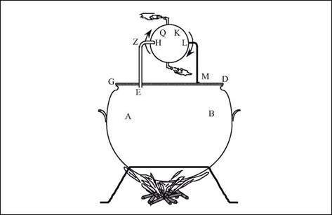
The principle of these automatic devices is based on the effects of pressure in fluid. Some of them use the siphon and connected chambers, as mechanisms for the automat­ic filling of a vase, mixing of two liquids, etc. Other devices are powered by the effects of gaseous expansion: the most remarkable invention is surely “Heron’s steam ball” (Figure 5.14), or eolipile, a device in which water brought to a boil emits steam, the pres­sure of which turns a ball around an axis. This is the principle of a steam engine, noth­ing less! But the technology (or perhaps society?) was not up to the task of industrial exploitation of this invention. [200]

The science of fluids at Alexandria under the Roman domination Heron of Alexandria and the “pneumatic” machines

Figure 5.14 “Heron’s steam ball”, the principle of a steam engine. “Let the cauldron AB be placed over a flame, with water; its opening will be closed by the cover GD, through which passes the bent tube EZH, its end penetrating into the small hollow sphere QK; diametrically opposite the extremity H, one mounts the pivot LM, which rests on the cover GD. One adds to the sphere two small bent tubes, welded to the sphere, diametrically opposed to each other and bent in opposite directions; these elbows must be at right angles, and the tubes perpendicular to the line HL. The following occurs when the cauldron is heated: the steam passes into the tube EZH to go into the sphere, and it leaves by the small bent tubes in the wall, and causes the sphere to turn, like figures that dance.”38

Damp Basement Solutions

To find the best cure for a damp basement, first determine whether the problem is caused by water outside migrating through foundation walls or by interior water vapor inside condens­ing on the walls. To determine which problem you have, duct tape a 2-ft.-long piece of alu­minum foil to the foundation, sealing the foil on all four sides. Remove the tape after 2 days. The wet side of the foil will provide your answer. Chapter 14 has more about mitigating moisture and mold.

CORRECTING CONDENSATION

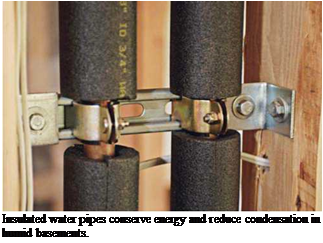
If the problem is condensation, start by insulating cold-water pipes, air-conditioning ducts, and other cool surfaces on which water vapor might con­dense. Wrap pipes with preformed foam pipe insu­lation. Wrap ducts and larger objects with sheets of vinyl-faced fiberglass insulation, which is well suited to the task because vinyl is a vapor barrier. Use duct tape or insulation tape to seal seams.

Next install a dehumidifier to remove excess humidity. For best results, install a model that can run continuously during periods of peak humidi­ty; place it in the dampest part of the basement at least 12 in. away from walls or obstructions. To prevent mold from growing in the unit’s collection reservoir, drain it daily and scrub it periodically.

Survey the basement for other sources of humidity. An unvented clothes dryer pumps gal­lons of water into living spaces; vent it outdoors. Excessive moisture from undervented kitchens and bathrooms on other floors can also migrate to the basement; add exhaust fans to vent them properly. Finally, weatherstrip exterior doors and keep them closed in hot, humid weather.

DAMPNESS DUE TO EXTERIOR WATER

Position and maintain gutters and downspouts so they direct water away from the house. And, if possible near affected walls, slope soil away from the house.

Besides those two factors, water that migrates through foundation walls or floors is more elu­sive and expensive to correct. Basically, you have three remedial options: (1) remove water once it gets in; (2) fill interior cracks, seal interior sur­faces, and install a vapor barrier; and (3) exca­vate foundation walls, apply waterproofing and improve drainage.

Option one: Remove water. Sump pumps are the best means of removing water once it gets
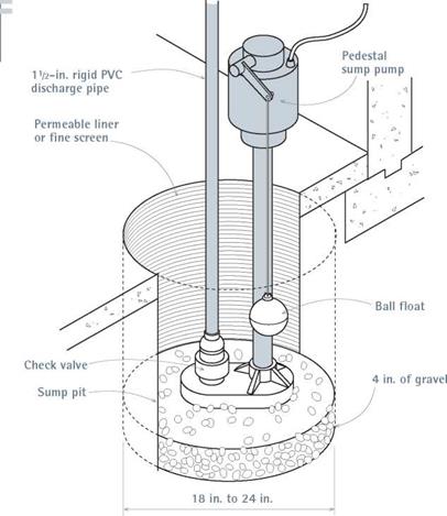
into a basement. If you don’t have a sump pump, you’ll probably need to break through the base­ment floor at a low point where water collects, and dig a sump pit 18 in. to 24 in. across. Line the pit with a permeable liner that allows water to seep in while keeping soil out, and put 4 in. of gravel in the bottom.

There are two types of sump pumps. Pedestal sump pumps stand upright in the pit. They are water cooled and have ball floats that turn the pump on and off. Submersible sump pumps, on the other hand, have sealed, oil-cooled motors, so they tend to be quieter, more durable, and more expensive. And because they are submerged, they allow you to cover the pit so nothing falls in. A й-hp pump of either type should suffice.

The type of discharge pipe depends on whether the pump is a permanent fixture or a sometime thing. Permanent pumps should have 112-in. rigid PVC discharge pipes with a check valve near the bottom to prevent expelled water from siphoning back down into the pit. If the water problem is seasonal, many people simply attach a 50-ft. gar­den hose and run it out a basement window. In either case, discharge the water at least 20 ft. from the house, preferably downhill and not directly into a neighbor’s property.

Option two: Interior solutions. If basement walls are damp, try filling cracks as suggested on p. 205 and applying damp-proofing coatings. (However, this approach won’t work if the walls are periodically wet. After scrubbing the base­ment walls, parge (trowel on) a cementitious coating such as Thoroseal® Foundation Coating or Sto Watertight Coat® or a polymer-modified system such as Bonsal’s Surewall®. These coat­ings can withstand higher hydrostatic pressures than elastomeric paints or gels. Epoxy-based coatings also adhere well but are so expensive that they’re usually reserved for problem areas such as wall to floor joints.

To further control moisture diffusion through the walls, install a vapor barrier. After parging the walls with a damp-proofing material, use con­struction adhesive to attach heavy (6-mil at a minimum) sheet polyethylene to the foundation walls. Then place sheets of rigid foam insulation over the plastic sheeting. Caulk and tape the foam seams to seal them. If the seams are airtight, the insulation layer becomes a second vapor barrier and makes condensation less likely because it iso­lates cool basement walls from warm air.

Option three: Exterior solutions. To water­proof exterior foundation walls, first excavate them. At that time, you should also upgrade the perimeter drains, as shown in "Foundation Drainage,” on p. 203. Then, after backfilling the excavation, slope the soil away from the house. That is, no waterproofing material will succeed if water stands against the foundation. Before applying waterproofing membranes, scrub the foundation walls clean and rinse them well.

► Liquid membranes are usually sprayed on, to a uniform thickness specified by the manufacturer, usually 40 mil. That takes train­ing, so hire a manufacturer-certified installer. Liquid membranes are either solvent based or water based. Modified asphalt is one popular solvent-based membrane that contains rubber­like additives to make it more flexible and durable. Asphalt emulsions are water based and widely used because, unlike modified asphalt, they don’t smell strong, aren’t flammable, and won’t degrade rigid foam insulation panels placed along foundation walls. Synthetic – rubber and polymer-based membranes are also water based; they’re popular because their inherent elasticity allows them to stay flexible and span small cracks. Note: Water-based membranes dry more slowly than solvent-based ones and can wash off if rained on before they are cured and backfilled.

► Peel-and-stick membranes are typically sheet or roll materials of rubberized asphalt fused to polyethylene. They adhere best on pre­primed walls. To install these membranes, peel off the release sheet and press the sticky side of the material to foundations. Roll the seams to make them adhere better. Peel-and-stick costs more and takes longer to install than sprayed – on membranes, but they’re thicker (60 mil, on average) and more durable. Though not widely used on residences, these materials seem justified on sites with chronic water problems. They’re often called Bituthene®, after a popular W. R. Grace Construction product.

► Air-gap membranes aren’t true mem­branes because they don’t conform to the surface of the foundation. Rather, they are
rigid plastic (polyethylene) sheets held out from the foundation by an array of tiny dim­ples, which creates an air-drainage gap. Water that gets behind the sheets condenses on the dimples and drips free, down to foundation drains. (For this system to work, you must coat the foundation walls first.) Air-gap sheets are attached with molding strips, clips, and nails; caulk the sheet seams.

► Until technology transformed water­proofing compounds, cementitious coatings rivaled unmodified asphalt as the most com­mon stuff smeared onto foundations. These days, acrylic additives make cement-based coatings a bit more flexible, but they will still crack if the foundation flexes. Bentonite, a vol­canic clay sheathed in cardboard panels, swells 10 times to 15 times its original volume when wet, keeping water away from foundation walls. Use construction adhesive or nails to attach the panels. These panels are costly and not widely available, and they can be ruined if rained on before the foundation is backfilled.

Подпись: PROTIP Waterproofing membranes are relatively fragile, especially those that are sprayed on. So after they're applied, they're often covered with rigid insulation, drain board, protection board, and the like. These rigid panels protect the membranes during backfilling, and insulate the foundation walls to reduce heat loss. Подпись: 1111image460I Pedestal Sump Pump

Cubic Yards of Concrete in Slabs of Various Thicknesses* t

/

Подпись: ^^^AREA (sq. ft.) 1.0 in. 1.5 in. 2.0 in. 2.5 in 3.0 in. 3.5in. 4.0 in. 4.5 in. 5.0 in. 5.5 in. 6.0 in 10 0.03 0.05 0.06 0.08 0.09 0.11 0.13 0.14 0.15 0.17 0.19 20 0.06 0.09 0.12 0.16 0.19 0.22 0.25 0.28 0.31 0.34 0.37 30 0.09 0.14 0.19 0.23 0.28 0.33 0.37 0.42 0.46 0.51 0.56 40 0.12 0.19 0.25 0.31 0.37 0.43 0.50 0.56 0.62 0.68 0.74 50 0.15 0.23 0.31 0.39 0.46 0.54 0.62 0.70 0.77 0.85 0.93 60 0.19 0.28 0.37 0.46 0.56 0.65 0.74 0.83 0.93 1.02 1.11 70 0.22 0.32 0.43 0.54 0.65 0.76 0.87 0.97 1.08 1.19 1.30 80 0.25 0.37 0.49 0.62 0.74 0.87 1.00 1.11 1.24 1.36 1.48 90 0.28 0.42 0.56 0.70 0.84 0.97 1.11 1.25 1.39 1.53 1.67 100 0.31 0.46 0.62 0.78 0.93 1.08 1.24 1.39 1.55 1.70 1.85 200 0.62 0.93 1.23 1.54 1.85 2.16 2.47 2.78 3.09 3.40 3.70 300 0.93 1.39 1.85 2.32 2.78 3.24 3.70 4.17 4.63 5.10 5.56 400 1.23 1.83 2.47 3.10 3.70 4.32 4.94 5.56 6.17 6.79 7.41 500 1.54 2.32 3.09 3.86 4.63 5.40 6.17 7.00 7.72 8.49 9.26 600 1.85 2.78 3.70 4.63 5.56 6.48 7.41 8.33 9.26 10.19 11.11 700 2.16 3.24 4.32 5.40 6.48 7.56 8.64 9.72 10.80 11.88 12.96 800 2.47 3.70 4.94 6.20 7.41 8.64 9.88 11.11 12.35 13.58 14.82 900 2.78 4.17 5.56 6.95 8.33 9.72 11.11 12.50 13.89 15.28 16.67 1,000 3.09 4.63 6.17 7.72 9.26 10.80 12.35 13.89 15.43 16.98 18.52
Подпись: This table can be used to estimate the cubic content of slabs larger than those shown. To find the cubic content of a slab measuring 1,000 sq. ft. and 8 in. thick, add the figures given for thicknesses of 6 in. and 2 in. for 1,000 sq. ft. f Courtesy of Bon Tool Company, © 2003, from Statistical Booklet: Contractors, Tradesmen, Apprentices (see also www.bontool.com).

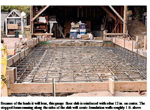
slabs consist of 4 in. of concrete poured over 4 in. of crushed rock, with a plastic moisture barrier between. In addition, garage floors are often reinforced with steel mesh or rebar to support greater loads and forestall cracking.

PREP STEPS

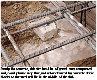
As with any concrete work, get plenty of help. Concrete weighs about 2 tons per cubic yard, so if your slab requires 10 cu. yd., you’ll need to move and smooth 40,000 lb. of concrete before it sets into a monolithic mass. Time is of the essence, so make sure all the prep work is done before the truck arrives: Tamp the crushed stone, spread the plastic barrier (minimum of 6 mil), and elevate the steel reinforcement (if any) on
dobie blocks or wire high chairs so it will ride in the middle of the poured slab. Finally, snap level chalklines on the basement walls or concrete forms to indicate the final height of the slab— you’ll screed to that level.

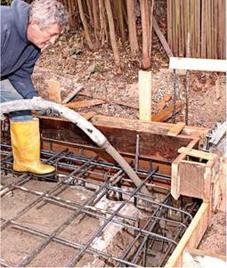
To pour concrete with a minimum of wasted energy, use a 2-in. (interior diameter) concrete – pump hose. A hose of that diameter is much lighter to move around than a 3-in. hose. Another advantage: It disgorges less concrete at a time, allowing you to control the thickness of the pour better. And a 2-in. hose gives easier access to distant or confined locations. Important: As you place concrete around the perimeter of the slab, be careful not to cover up the chalklines you snapped to mark the slab height. And as you

Подпись: Ordering Concrete: Be Specific Concrete has so many different uses (such as floors, foundations, and countertops) and so many admixtures (water reducers, retardants, accelerants, air entrainers, and so on) that the best way to get the mix you need is to specify its use and desired characteristics. That is, when ordering the mix, tell the supplier the quantity you need (in cubic yards), how the concrete will be used (driveway, foundation, patio slab), the loads it will bear, how far it must be pumped, how it will be finished, and other such details. If you're pouring a slab that will have a smooth finish, you might specify "a 2,500 psi mix, but a true five-sack mix," which will be "creamy" enough to finish with a steel trowel. If you specify a 2,500 psi mix but don't describe the finish, the supplier might use four sacks of cement and a water reducer to attain that strength. However, with less cement in it, the mix would be sandier and more difficult to finish. Where the concrete will be placed can also affect the mix. For example, concrete for a second-story patio far from the street may require a smaller, 2-in. (inner diameter) hose to pump it, so the supplier may specify smaller aggregate (3/s-in. vs. 3/4-in.) to facilitate flow. Aggregate size, in turn, affects load-bearing capacity, so a mix with 3/s-in. gravel is often bumped up, say, to 3,000 psi. If the patio slab will also be steel troweled, the mix thus becomes "a 3,000 psi, 3/s-in. aggregate, true six-sack mix." Well, you get the point: Be specific. Estimating the amount of concrete in cubic yards is straightforward: The calcula-tion is width x length x depth (in feet) of the area you want to cover. You then divide that result by 27 (as there are 27 cu. ft. in 1 cu. yd.). If you're pouring a slab, "Cubic Yards of Concrete in Slabs of Various Thicknesses," on p. 221, calculates cubic yards based on the slab thickness (in inches). Most concrete-mixer trucks can hold 9 cu. yd. to 11 cu. yd. So if your pour requires more than one truck, ask the supplier to time deliveries 90 minutes apart so you have enough time to deal with each delivery. Finally, don't shave the estimate too close; far better to have too much concrete than too little. Подпись: Because of the loads it will bear, this garage floor slab is reinforced with rebar 12 in. on center. The stepped forms running along the sides of the slab will create foundation walls roughly 1 ft. above grade. place concrete in the slab footings, drive out the air pockets by using a concrete vibrator.
Establishing screed levels. If the slab is only 10 ft. or 12 ft. wide, you can level the concrete by pulling a screed rail across the top of form boards. Otherwise, create wet screeds (leveled columns of wet concrete) around the perimeter of the slab and one in the middle of the slab to guide the screed rails. The wet screeds around the perimeter are the same height as the chalk­lines; pump concrete near those lines and level it with a trowel. This technique is very much like that used to level tile mortar beds, as explained in Chapter 16.

The wet screed(s) in the middle should be more or less parallel to the long dimension of the slab. There are several ways to establish its height, but the quickest way is to drive 18-in. lengths of rebar into the ground every 6 ft. or so, and then use a laser level or taut strings out from perime­ter chalklines to establish the height of the rebar. In other words, the top of the rebar becomes the top of the middle wet screed. When you’ve troweled that wet screed level, hammer the rebar below the surface, and fill the holes later.

SCREEDING AND FLOATING

Screeding is usually a three-person operation: two to move the screed rail back and forth, strik­ing off the excess concrete, and a third person behind them, constantly in motion, using a stiff rake or a square-nose shovel to scrape down high spots or to add concrete to low ones. You can use a magnesium screed rail or a straight 2×4 to strike off, but the key to success is the raker’s maintaining a good level of concrete behind the screeders, so the screed rail can just skim the crest of the concrete, without getting hung up or bowed by trying to move too much material.

Screeding levels the concrete but leaves a fairly rough surface, which is then smoothed out with a magnesium bull float, a long-handled float that also brings up the concrete’s cream (a watery cement paste) and pushes down any gravel that’s near the surface. This creates a smooth, stone-free surface that can be troweled and compacted later.

A bull float should float lightly on the surface. As you push it across the concrete, lower the han­dle, thereby raising the far edge of the float. Then, as you pull the float back toward you, raise the handle, raising the near edge. In this manner, the leading edge of the bull float will glide and not dig into the wet concrete.

Подпись: Fill slab footings first; then vibrate them to drive out any air pockets. Because placing a concrete slab usually entails standing in it, wear rubber boots.
image454
Подпись: Ready for concrete, this site has 4 in. of gravel over compacted soil, 6-mil plastic atop that, and rebar elevated by concrete dobie blocks so the steel will lie in the middle of the slab.

FINISHING THE SLAB

After the bull float raises water to the surface, you must wait for the water to evaporate before finishing the concrete. The wait depends on the weather. On a hot, sunny day, you may need to wait less than an hour. On a cool and overcast day, you might need to wait for hours. Once the water’s evaporated, you have roughly 1 hour to trowel and compact the surface. When you think the surface is firm enough, put a test knee board atop the concrete and stand on it. If the board sinks % in. or more, wait a bit. If the board leaves only a slight indent that you can easily hand float further and then trowel smooth, get to work.

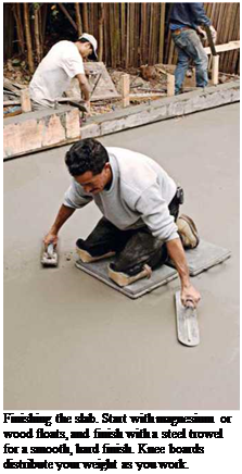
As the photos show, knee boards distribute your weight and provide a mobile station from which to work. You’ll need two knee boards in order to move across the surface, moving one board at a time. Then, kneeling on both boards, begin sweeping with a magnesium hand float or with a wood float, if you prefer a rougher finish. Sweep back and forth in 3-ft. arcs, raising the far edge of the float slightly as you sweep away and raising the near edge on the return sweep. The “mag” float levels the concrete.

After you’ve worked the whole slab, it’s time for the steel trowel, which smooths and compacts the concrete, creating a hard, durable finish.

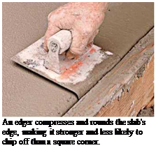
As the concrete dries, it becomes harder to work, so it’s acceptable to sprinkle very small amounts of water on the surface to keep it work­able. Troweling is hard work, especially on the back. When the concrete’s no longer responding to the steel trowel, edge the corners and then cover the concrete with damp burlap before call­ing it a day. If the weather’s hot and dry, hose down the burlap periodically—every hour, at

Подпись: Finishing the slab. Start with magnesium or wood floats, and finish with a steel trowel for a smooth, hard finish. Knee boards distribute your weight as you work. Подпись: An edger compresses and rounds the slab's edge, making it stronger and less likely to chip off than a square corner. Подпись: Insulated water pipes conserve energy and reduce condensation in humid basements. least—and keep the slab under cover for 4 or 5 days. At the end of that time, you can remove the forms. Concrete takes a month to cure fully.
Size Determination for Culverts with Outlet Control

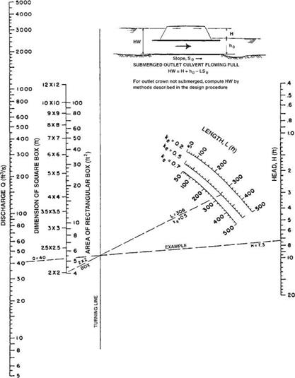
The headwater depth for a culvert operating under outlet control may be determined with the aid of the outlet control nomographs in HDS 5. An example of these nomo­graphs for box culverts is shown in Fig. 5.15. The following procedure may be used to determine the head H from the nomographs. The length L (ft), entrance coefficient ke, and design discharge must be known. Locate L on the appropriate ke curve, and connect this point with the proposed culvert size. Locate the design discharge and extend a line from that point through the turning point intersection of the previous line to read the

Size Determination for Culverts with Outlet Control

FIGURE 5.14 Flow nomograph for box culvert under inlet control. (From “Hydraulic Design of Highway Culverts," HDS 5, FHWA, with permission)

value of the head H (ft) on the right. For example, assume L = 306 ft, ke = 0.5, a 2-ft X 2-ft box, and Q = 40 ft3/s. The nomograph shows that H = 7.3 ft. The headwater depth, HW, may then be determined by geometry from the equation

Size Determination for Culverts with Outlet Control

FIGURE 5.15 Flow nomograph for box culvert under outlet control with n = 0.012. (From "Hydraulic Design of Highway Culverts," HDS 5, FHWA, with permission)

where the terms are defined by the inset figure in the nomograph. (Note: To use the chart with SI units, first convert from SI units to U. S. Customary units—1 ft = 0.305 m, 1 ft2 = 0.0929 m2, 1ft3/s = 0.0283 m3/s). Where the outlet is submerged, ho is equal to the tail – water depth just downstream of the outlet and may be calculated from Manning’s equa­tion as applied to the channel. Where the outlet is not submerged, ho is equal to the greater of the tailwater depth or one-half of the sum of the culvert height plus the critical depth, (dc + D)/2. By examining different alternatives, a culvert can be selected that pro­vides the required flow within the allowable headwater depth.

Capping a Foundation

Capping an old foundation with new con­crete is relatively rare but is done when the existing foundation is in good condition and needs to be raised because the house’s framing is too close to the ground, allowing surface water to rot sills and siding.

To raise wood members sufficiently, the new cap must be 8 in. above grade. At the very least, that means shoring up the structure, removing the existing mudsill, shortening the pony-wall studs, drilling the old foundation, epoxying in rebar pins to tie the new concrete to the old, and pouring new concrete atop or around some part of the existing foundation. That’s a lot of work. So if the existing founda­tion is crumbling or lacks steel reinforcement, you should replace it altogether.

On the other hand, if the house lacks pony walls and the joists rest directly on the founda­tion, you have basically two options: (1) grade the soil away from the house to gain the neces­sary height, which may not be possible if the foundation is shallow, or (2) jack up the house at least 8 in., which means hiring a house mover. Here again, replacing the foundation is usually more cost effective.

Otherwise, cut the tops of the stakes off and leave the rest embedded in the new concrete.

Hammer the outside of the form boards and then use a concrete vibrator, to drive out the air pockets. For this, insert the hose-like vibrator into the forms. As the concrete approaches the tops of forms, signal the pump to shut off so that the concrete doesn’t spill over the sides. When the forms are full and vibrated, use a trowel to flatten the top of the wall and sponge off any globs on the stakes and forms. Allow the concrete to cure 3 days at a minimum and 7 days for the optimum, before removing the forms and shoring, replacing the siding, and tightening down the washered anchor bolts. For further pro­tection against moisture, apply below-grade waterproofing to the outside wall and footing before backfilling.

Concrete Work

Concrete is a mixture of portland cement, water, and aggregate (sand and gravel). When water is added to cement, a chemical reaction, called hydration, takes place, and the mixture hardens around the aggregate, binding it fast. Water makes concrete workable, and cement makes it strong. The lower the water to cement ratio (w/c), the stronger the concrete.

POURING A CONCRETE SLAB

Pouring (or placing) a concrete slab is pretty much the same procedure, whether for patios, driveways, basements, or garage floors. Most

CALCULATING MINIMUM PLUMBING FACILITIES

C

Подпись:alculating minimum plumbing facilities is a common part of a master plumber’s job. Knowing and understanding what is required in a build­ing is not only a requirement for plumbers. Architects and engineers are often the people who determine the requirements for a new building. Local plumbing codes dictate minimum plumbing facilities. All plumbers have to do is understand the information provided for them in their codebooks. The in­formation given by the codes is fairly simple, but gaining a complete under­standing of it can be a bit intimidating. If the process is approached too lightly, mis­conceptions can cause mistakes. The peo­ple responsible for determining what plumbing will be included in a building cannot afford to make mistakes.

CALCULATING MINIMUM PLUMBING FACILITIESПодпись: ► sensible shortcutIt is common for plumbers to be pro­vided with detailed blueprints when bid­ding jobs. The drawings will normally be submitted to a code enforcement office for approval. During this process, there are many ways for mistakes to be caught.

Подпись:If the person drawing the plans makes an error, the code officer who is working with the drawings is likely to find the problem. Plumbers bidding the job might catch the discrepancy.
Some jobs are not engineered. There are times when plumbers are expected to calculate the minimum plumbing needs for a building. Plus, plumbers who wish to

165

gain a master’s license will have to pass an examination that is likely to require them to compute plumbing requirements. With this in mind, let’s look at some tables that might be used to figure the requirements for plumbing fix­tures in various types of buildings.

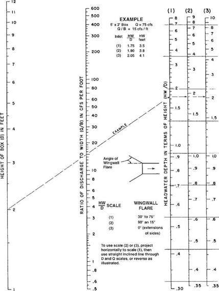
Size Determination for Culverts with Inlet Control

Once the design discharge and allowable headwater are determined and the culvert alignment and slope decided upon, an efficient culvert size may be found through the use of nomographs as shown in “Hydraulic Design of Highway Culverts,” Hydraulic Design Series 5, FHWA.

An example of an inlet control nomograph is shown in Fig. 5.14. Since the structure size is not known, the design is an iterative process. To use the chart, the trial culvert size and inlet configuration, design discharge, allowable headwater depth, culvert length, and culvert slope must be known. The relationship of the inlet control headwater to the diameter or height of the culvert (HW/D) is read directly from the inlet control nomograph by extending a line from the culvert size scale (left scale) through the discharge/bottom width ratio scale (center scale) to the scale of the headwater depth in terms of height (right scale). The inlet control headwater equals this value multiplied by D. For example, assume a 5-ft X 2-ft box culvert with the design storm, Q, equal to 75 ft3/s. The nomograph shows that HW/D = 1.75, 1.90, or 2.05, depending upon the inlet configuration. By multiplying these values by the box rise of 2 ft, the correspond­ing headwater depths are found to be 3.5 ft, 3.8 ft, and 4.1 ft, respectively. (Note: To use the chart with SI units, first convert from SI units to U. S. Customary units—1 ft = 0.305 m, 1ft3/s = 0.0283 m3/s).

Water Vapor Infiltration

The infiltration of water vapor as a soil gas is a common problem that may be due to several conditions, including high water tables, un­derground springs, or hardpan soils that cause excess water to remain at the surface. Certain soils hold moisture so that, instead of perco­lating through the soil, water vapor evaporates and travels upwards. Even with proper perim­eter drainage around the building, which will take care of flowing water, this residual water vapor maybe sufficient to cause damage.

Soil Gas Mitigation and Prevention

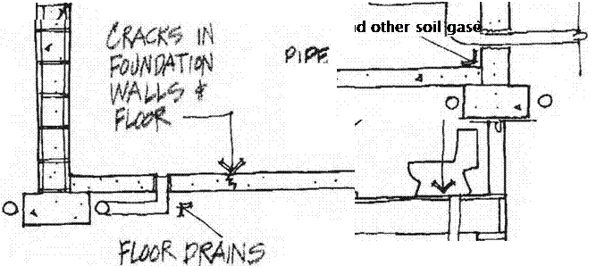
Foundation detailing and design affect the amount of soil gases that will accumulate in a building if they are present in the soil. The basement is the most vulnerable to radon and other soil gas seepage because it has the larg­est surface area in contact with the soil. Crawl spaces under buildings, especially unvented ones, can concentrate these gases. The gas is easily transferred to the living space if there is not an effective air barrier separating the liv­ing space from the soil under the crawl space. A slab-on-grade can form an effective bar­rier against soil gas, but any cracks, joints, or penetrations in the slab will create routes for soil gas to enter. Where elevated soil gas lev­els are suspected, clay-based and other types of permeable floor systems that come into di­rect contact with the ground are not recom­mended without supplementary controls.

Methods of Soil Gas Mitigation

The EPA conducts radon mitigation train­ing programs for contractors. State offices can provide you with the names of contrac­tors who have been trained and qualified un­der the EPAs Radon Contractor Proficiency

Program. Contractors who understand radon mitigation will have a basis for understanding any type of soil gas mitigation. A good strat­egy for soil gas mitigation consists of the fol­lowing three components:

• Blockage of all potential entry routes: Concrete slabs and basement walls must be properly reinforced to minimize crack­ing. (Refer to Division з for information on concrete reinforcement.) Cracking in concrete floors is a common occurrence. Cold joints and expansion joints help con­trol where cracking will occur so it can be more easily and reliably sealed. Plumbing penetrations must be sealed with a flexible caulk. (Refer to recommended caulking materials in this chapter.) Special barrier sheeting placed under the slab or over the soil in the crawl space will further block soil gas from entering. Basement walls must be thoroughly parged. Concrete floor slabs and block or poured concrete walls can by coated with AFM Safecoat DynoSeal or another low-emissions flexible membrane to further seal cracks and joints.

• Prevention of negative pressurization of the building envelope: A home that has lower air pressure than the surround­ing outside environment will be negatively pressurized. This creates a vacuum that will suck air and soil gases into the build­ing wherever there happens to be a route of entry, including tiny cracks in the slab, crawl space soil barrier, or basement walls. To prevent negative pressurization, it is important to provide sources for the con­trolled supply of outside air into the home to replace the air lost through the operation of various appliances such as exhaust fans and clothes dryers. Creating a condition

гттмтт

4 J cjNT* "ЧЬ

.fto*2v

-*•*, eot,*

і!£*?

Water Vapor Infiltration

where there is a slight positive pressuriza­tion can be an effective means of reducing levels of radon and other soil gases. Strat­egies for providing proper pressurization are discussed in Division 15.

• Collection of soil gas from under the building envelope and redirection away from the building: There are several methods for accomplishing this task. Pro­fessional Discount Supply is a company that specializes in radon mitigation sup­
plies. Many of these same materials are ap­plicable to all soil gas mitigation.

You may want to include the following col­lection methods in your specifications, along with instructions for proper installation of barriers and sealants:

Method 1: A 4-inch layer of aggregate is placed under the building envelope. A 4-inch-diameter perforated pipe is laid in the

Allowable Headwater Depth

The allowable headwater depth is the depth of ponded water permitted at the entrance to a culvert. Allowable headwater depths are generally classified as either physical controls or arbitrary controls.

Physical headwater controls are topographic features that should be protected against periodic inundation. They include the roadway pavement and upstream pro­ductive property or structures. Additionally, high points between adjacent watersheds should typically be used as physical headwater controls. The use of a watershed break elevation as a headwater control will protect against the unnecessary diversion of runoff from a watershed to an adjacent watershed.

Arbitrary headwater controls are typically used to ensure the efficient operation of the culvert while protecting the roadway embankment from erosion and subsequent washout. The control may be a function of either the design flood or the base flood. Typical limits include a percentage of the barrel diameter or rise such as 1.2D or 120 percent of the barrel diameter or rise, or a permitted depth of ponding above the barrel such as D + 2 ft. Greater depths of ponding for the base flood are typically per­mitted. Large-span structures usually have more restrictive limitations.