Principles of Data Collection and Storage

7.2.1 Data Collection

It is a general rule that data must always be collected with a specific purpose in mind. This rule is as much true concerning contaminant levels in soils and groundwaters as it is in any other field. Therefore, before any sampling regime is contemplated and before any specimens are analysed, it is essential to decide the purpose for which samples and analyses might be required. Then a systematic sampling programme and network needs to be designed and planned with the purpose and constraints clearly in view. It is usually a non-routine task to identify the questions that need answering by the sampling and analysis programme. Perhaps these will be suggested because of standards set by an environmental regulator. Perhaps they will arise be­cause of a client’s desire to establish or maintain a reputation for environmentally responsible behaviour. Perhaps they will be set as a consequence of the desire to establish a benchmark for future work. Probably there will be some combination of these prompts together with others. It is the monitoring agency’s job to ensure that the data collected is that which is really needed and not that habitually collected. There is no point in collecting data that is never used, nor will it usually be possible to go back and collect missing data.

If a road is to be constructed of an unusual material, then a programme of labora­tory assessments of the leaching potential of the material might be established long before construction is planned. The purpose here would probably be to understand the possible yields of contaminants in time, and in concentration, under conditions that are expected to pertain in-situ once construction commences and, also, after construction is completed. Initially a wide range of elements might be studied to de­termine what species are of concern within the runoff contaminants (see Chapter 6). Later studies might take place on a reduced number, only addressing those elements previously identified as potentially giving concern. Probably some kind of computer modelling will be intended to extend the in-isolation laboratory results to in-situ conditions. In that case, it is necessary to obtain data in a form suitable for use in the selected modelling program. Once construction commences, data collection in-situ will most probably be required. At that time the aim would be to confirm that the interpretation made from the laboratory assessments and numerical modelling are, indeed, valid.

In examples where a potentially contaminating material is to be used, for which construction experience and contaminant behaviour is already understood, labora­tory studies might be restricted to confirming that the material is, indeed, similar to previously used examples. In-situ investigations might then be limited to confirming similar behaviour to that previously experienced. In practice, no two installations are identical, so some sample collection and analyses are likely to be required to explore the specific application.

For many studies of contaminants in the road environment, a “base-line” study is required. This investigation has the aim of characterizing the in-situ ground and water quality condition prior to a planned action. Thus, the naturally occurring conditions of a “greenfield” site would be recorded before a new road was constructed in the vicinity, or a contaminated site would be characterised prior to activity designed to improve water quality. In both cases the aims are, first, to be able to determine the effects of the activity on the surrounding ground and water quality and, secondly, to assess whether some intervention is, therefore, needed.

Other patterns of Batching constituents in a Batch plant

The KGO-III (Viman et al., 2004) method has been experimentally applied in Sweden since 2002. It consists of changing the order of batching and mixing the constituents in a batch plant. The suggested KGO-III mixing order is as follows:

FIGuRE 9.5 One sequence of batching SMA constituents into a pugmill using a loose form of stabilizer. Notice that the times depend on the type of pugmill. (From Graf, K., Splittmastixasphalt – Anwendung und Bewahrung. Rettenmaier Seminar eSeMA’06. Zakopane [Poland], 2006. With permission.)

Подпись: Coarse and fine aggregates Added filler Stabilizer (loose fibers) Binder Wet mixing Discharging
Other patterns of Batching constituents in a Batch plant
Подпись: 50
Other patterns of Batching constituents in a Batch plant
Подпись: 10 s
Подпись: 10
Подпись: 60
Подпись: 20 Подпись: 70

FIGURE 9.6 Another sequence of batching SMA constituents into a pugmill using a loose form of stabilizer. Notice that the times depend on the type of pugmill. (From Schunemann, M., Faserqualitat. Eine wesentliche Voraussetzung zum Herstellen von qualitatsgerechten Asphaltbefestigungen. Rettenmaier Seminar eSeMA’07, Zakopane [Poland], 2007.)

• Stage 1—mixing binder with an aggregate larger than 4 mm

• Stage 2—adding filler only to dissolve it in the mixture

• Stage 3—adding fine fractions (0.063-4 mm)

Changing the order of batching and mixing are aimed at achieving a thicker binder film on the coarse aggregate. As we know, the smallest grains of aggregate are the first to be coated with binder, in a way capturing the binder and interfer­ing with the creation of thick binder films on the coarse aggregate. Therefore the first stage of the KGO-III approach is intended to coat the bigger grains before the smaller ones.

According to Viman et al. (2004), by employing this approach, about 0.5% less binder may be used in comparison with a typical mixture. It has also been shown that the production temperature of the mixture can be reduced by approxi­mately 30°C. Thus not only can the manufacturer benefit from savings in binder and energy costs, but the process is also favorable for the environment due to lower air pollution (e. g., less odors, fumes, and heat). Six different plants and manufacturers have produced in total 500,000 tons of the mixture according to KGO-III since 1998.

Overall summary of AFOSM reliability method

Convergence criteria for locating the design point. The previously described Hasofer-Lind and Ang-Tang iterative algorithms to determine the design point indicate that the iterations may end when x(r) and x(r+1> are sufficiently close. The key question then becomes what constitutes sufficiently close. In the ex­amples given previously in this section, the iterations were stopped when the
difference between the current and previous design point was less than 0.001. Whereas such a tight tolerance worked for the pipe-capacity examples in this book, it might not be appropriate for other cases, particularly for practical prob­lems. Thus alternative convergence criteria often have been used.

In some cases, the solution has been considered to have converged when the values of в(г) and віт+1) are sufficiently close. For example, Ang and Tang (1984, pp. 361-383) presented eight example applications of the AFOSM method to civil engineering systems, and the convergence criteria for differences in в ranged from 0.025 to 0.001. The Construction Industry Research and Informa­tion Association (CIRIA, 1977) developed an iterative approach similar to that of Ang and Tang (1984), only their convergence criterion was that the perfor­mance function should equal zero within some tolerance. The CIRIA procedure was applied in the uncertainty analysis of backwater computations using the HEC-2 water surface profiles model done by Singh and Melching (1993).

In order for iterative algorithms to locate the design point to achieve conver­gence, the performance function must be locally differentiable, and the orig­inal density functions of Xk must be continuous and monotonic, at least for Xk < xk* (Yen et al., 1986). If the performance function is discontinuous, it must be treated as a series of continuous functions.

The search for the design point may become numerically more complex if the performance function has several local minima or if the original density functions of the Xk are discontinuous and bounded. It has been found that some of the following problems occasionally may result for the iteration algorithms to locate the design point (Yen et al., 1986):

1. The iteration may diverge or it may give different в values because of local minima in the performance function.

2. The iteration may converge very slowly when the probability of failure is very small, for example, pf < 10-4.

3. In the case of bounded random variables, the iteration may yield some xk* values outside the bounded range of the original density function. However, if the bounds are strictly enforced, the iterations may diverge.

Yen et al. (1986) recommended use of the generalized reduced gradient (GRG) optimization method proposed by Cheng et al. (1982) to determine the design point to reduce these numerical problems. However, the GRG-based method may not work well when complex computer models are needed to determine the system performance function.

Melching (1992) applied the AFOSM method using the Rackwitz iterative algorithm (Rackwitz and Fiessler, 1978), which is similar to the Ang-Tang algorithm, to determine the design point for estimation of the probability of flooding for 16 storms on an example watershed using two rainfall-runoff models. In this application, problems with performance function discontinu­ities, slow convergence for small values of pf, and divergence in the estimated в values were experienced for some of the cases. In the case of discontinuity in the performance function (resulting from the use of a simple initial loss – continuing loss rate abstraction scheme), in some cases the iterations went back and forth between one side of the discontinuity and the other, and conver­gence in the values of the xk s could not be achieved. Generally, in such cases, the value of в had converged to the second decimal place, and thus a good approximation of в* corresponding to the design point was obtained.

For extreme probability cases (в > 2.5), the iterations often diverged. The difference in в values for performance function values near zero typically was on the order of 0.2 to 0.4. The iteration of which the в value was smallest was selected as a reasonable estimate of the true в* corresponding to the design point. In Melching (1992), the pf values so approximated were on the order of 0.006 to 0.00004. Thus, from a practical viewpoint of whether or not a flood is likely, such approximations of в* do not greatly change the estimated flood risk for the event in question. However, ifvarious flood-mitigation alternatives were being compared in this way, one would have to be very careful that consistent results were obtained when comparing the alternatives.

A shortcoming of the afosm reliability index. As shown previously, use of the

AFOSM reliability index removes the problem of lack of invariance associated with the MFOSM reliability index. This allows one to place different designs on the same common ground for comparing their relative reliabilities using в-AF^M. A design with higher value of влгозм would be associated with a higher reliability and lower failure probability. Referring to Fig. 4.14, in which failure surfaces of four different designs are depicted in the uncorrelated standardized parameter space, an erroneous conclusion would be made if one assesses the relative reliability on the basis of the reliability index. Note that in Fig. 4.14 the designs A, B, and C have identical values of the reliability index, but the size of their safe regions SA, SB, and SC are not the same, and in fact, they satisfy SA c SB c SC. The actual reliability relationship among the three de­signs should be ps(A) < ps(B) < ps(C), which is not reflected by the reliability index. One could observe that if the curvatures of different failure surfaces at the design point are similar, such as those with designs A and B, relative relia­bilities between different designs could be indicated accurately by the value of reliability index. On the other hand, when the curvatures offailure surfaces are significantly different, such as those for designs C and D, вAFOsM alone could not be used as the basis for comparison.

For this reason, Ditlevsen (1979) proposed a generalized reliability index во = Ф(у), with y being a reliability measure obtained from integrating a weight function over the safe region S, that is,

Y = Ф (x) d x (4.83)

J x es

in which ф (x) is the weight function, which is rotationally symmetric and pos­itive (Ditlevsen, 1979). One such function that is mathematically tractable is

xk

Overall summary of AFOSM reliability method

Figure 4.14 Nonunique reliability associated with an identical relia­bility index.

the K-dimensional standardized independent normal PDF. Although the gen­eralized reliability index provides a more consistent and selective measure of reliability than ^atosm for a nonlinear failure surface, it is, however, more computationally difficult to obtain. From a practical viewpoint, most engineer­ing applications result in the general reliability index whose value is close to eAFoSM. Only in cases where the curvature of the failure surface at the design point is large and there are several design points on the failure surface would the two reliability indices deviate significantly.

. EXTERIOR HINGED DOORS

. EXTERIOR HINGED DOORS. EXTERIOR HINGED DOORSПодпись:. EXTERIOR HINGED DOORSПодпись: SLIDING DooRПодпись: FIXED DOOR SCREEN DOORПодпись:. EXTERIOR HINGED DOORS

Sliding doors, whether they are wood, vinyl, fiber­glass, or aluminum, fasten to a building more like a window than like a hinged door. Because the weight of a sliding door remains within the plane of the wall, there is no lateral loading on the jamb of the door unit. Sliding doors are therefore supported on the sill and can be attached to the building like windows—through the casing or with a nailing fin. As with sliding windows most sliding-door manufacturers recommend not fastening the nailing fin at the head because header deflection can impede door operation.

Sliding doors are trimmed to the finish materials of the wall in the same way as swinging doors and win­dows (see 92-94).

HEADER SEE 68-70 SHEATHING

DOOR WRAP IF EXPOSED TO WEATHER SEE 89

NAILING Fin on

sheathing & under moisture BARRIER

SIDING

caulk SEE 106

flashing if exposed to weather SEE 103b & c

insulate rough-opening cavity.

jamb extender to make jamb flush with interior

WALL FINISH

Mixing SMA with a Loose Stabilizer

When incorporating a loose stabilizer, which is usually packed in shrink-wrapped bags, extra time is needed for dry mixing the stabilizer with aggregate. A bag of stabilizer is thrown into the pugmill when the filler is being batched, and then an extra period (about 3 seconds) of dry mixing the fibers with the aggregate follows. Because of this, they are released from the bag and evenly distributed in the mixture. The binder is batched onto the dispersed fibers and aggregates, and additional wet stage mixing time follows. Again, one should to remember that too long a dry mix­ing time could destroy loose fibers.

Figure 9.5 depicts one sequence of the batching of SMA constituents into the pugmill with the use of a loose stabilizer. An example of another batching sequence is shown in Figure 9.6.

The NAPA SMA Guidelines QIS 122 recommend increasing the dry mixing time by 5-15 seconds in comparison with other mixtures without stabilizers. The wet mixing time should be increased by a minimum of 5 seconds when cellulose fibers are used and by not more than 5 seconds when mineral fibers are used.

Replacing a Shallow Foundation

If you decide to replace a shallow foundation, begin by checking local building codes for foun­dation specs appropriate for your area. Before

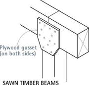
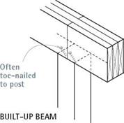
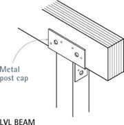
image433Подпись: Lally column capПодпись: Lally column (metal) —Подпись: (engineered lumber) (engineered lumber)Подпись: When it's necessary to construct a girder from several pieces of lumber, support each girder joint by placing a post or column beneath it. Many building codes also require metal connectors or plywood gussets at such joints to join posts to beams.

beginning foundation work, be sure to review this chapter’s earlier sections on shoring and jacking. Then survey the underside of the house and the area around the foundation for pipes, ducts, and other potential obstructions. If you can reposition jacks or move shoring slightly to avoid crushing or disconnecting drains, water pipes, and the like, do so.

Remember, jacking timbers and shoring are temporary supports. Complete the job and lower the house onto foundation elements as soon as possible. Work within your means, skills, and schedule: If you can’t afford a house mover to raise the house and replace the whole founda­tion, do it one wall at a time.

REPLACING MUDSILLS

Mudsills are almost always replaced when foun­dations are. With the framing exposed, it’s easy to install new pressure-treated or redwood mudsills that resist rot and insects. At the same time, replace rotted or insect-infested pony-wall studs. (If just a few studs are rotted, cut away the rot and nail a pressure-treated sister stud to each. If the bottom 1 in. or 2 in. of many studs has rotted, you might also install a thicker mudsill to make up for the amount you cut off stud bottoms.) If the siding is in good shape, remove just enough to expose the mudsills and rotten studs; the sid­ing holds the pony-wall studs in place and keeps them from “chattering” while you cut them.

(Pony walls shown on p. 209.) You’ll also need to punch through the siding to install temporary needle beams, discussed earlier in this chapter.

I Girder (Beam) Supports

image436

image437

Replacing a Shallow Foundation

Beam Span Comparison

Typical

joist


Header or other support


Beam Span Comparison


Beam


JOIST SPAN (x/2 + y/2)

8 FT. 10 FT. 12 FT. 14 FT. BEAM TYPE BEAM SPAN (ft.)


(2) 2×8 built-up beam

6.8

6.1

5.3

4.7

4×8 timber

7.7

6.9

6.0

5.3

3% in. x 71/2 in. glue-laminated beam

9.7

9.0

8.3

7.7

ЗУ2 in. x 71/ in. PSL beam

9.7

9.0

8.5

8.0

(2) 13/4 0=in. x 71/2in. LVL (unusual depth)

10.0

9.3

8.8

8.3

4×8 steel beam (W8 x 13 A36)

17.4

16.2

15.2

14.1


Joist span y


Header


72


Use this drawing and table for estimating beam sizes and comparing beam types for uniform floor loads of a 40-psf (pounds per square foot) live load and a 15-psf dead load. Have a structural engineer calculate your actual loads.


Beam supports 1/2 of each joist span, or x/2 + y/2. See table at right.


Replacing a Shallow Foundation

Подпись: If a new foundation section isn't terribly long or deep, use an electric demolition hammer with a shovel bit to excavate the trench. This tool is particularly helpful when there's no room to swing a pick. Shovel bits cut a nice, clean edge and dig themselves in, even in heavy clay. Then you simply shovel out the loosened soil. 1111 Подпись: Leveling a House In theory, you can level a house using individual hydraulic jacks. And if the house has only one or two low spots, you may succeed. However, the framing of a house will usually have sagged and settled, increasing the likelihood that jacking one area will raise an adjacent area too high. Heavily loaded points in multistory houses may resist being raised at all and when they finally do move, it's often sudden, loud, and frightening. Leveling a house is far more likely to succeed if done by a house mover with a unified hydraulic jacking system, in which jacks are interconnected, via hoses, to a central console that monitors the load on each jack. Thus, instead of 12 workers trying to turn 12 jacks at exactly the same time, a single operator at the console can ensure that the jacks rise at the same—or variable-rates, to the desired height. That desired height is determined beforehand by the foundation contractor, house mover, structural engineer, and—on occasion—the architect. Most often, the house mover works from a master reference point outside, against which house corners are read to determine whether they need raising or lowering. (For example, corner 1 might be listed as +3/ in.; corner 3, as -1/ in.; and so on.) Once the corners are leveled, the framing in the middle of the house is fine-tuned. Even when professionals level a structure, there's invariably damage to the finish surfaces inside, such as cracked plaster or popped drywall seams, door latches that no longer meet strike plates, trim that's askew, and windows and doors that bind during opening or shutting. Consider all this before you jack. Raising only the most out-of-level areas may be more cost-effective than leveling floors perfectly. Moreover, gently sloping floors may add character to an older house. Подпись: This old mudsill rotted out because the foundation was too close to the ground. After using a laser level to transfer the height of the new foundation, this builder snapped a chalkline across the pony-wall studs to indicate the height of the new sill.image438

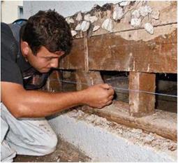
Once you’ve jacked up and shored the house framing, lay out the height of the new sill by snapping chalklines across the pony-wall studs. Use a laser level to indicate where the chalk marks should go or, if the old foundation is level, measure up from it. Although the line should be as level as possible, small variations will be accommodated when the concrete is poured up to the bottom of the mudsill.

With the siding removed, use a square to extend the cutoff marks across the face of the studs; a square cut optimizes load bearing from the stud onto the mudsill. Use a reciprocating saw to make the cuts. If the first stud chatters as you attempt to cut through it, tack furring strips to all the studs, just above the cut-line to bolster successive studs. Then remove the old mudsill and rotted stud sections. Chances are the old mudsill will not be bolted to the foundation.

The replacement sill should be foundation – grade heart redwood, pressure-treated Douglas fir, or yellow pine to resist insects and moisture and should be end-nailed upward into the solid remnants of each stud, using two 16d galvanized common nails. Use a pneumatic nailer to nail up the new mudsill; it does the job quickly. However, predrill anchor bolt holes into the new
mudsills before nailing them to stud ends. Anchor bolts will secure house framing to the foundation after you pour it.

STEP 8 SEAL THE ROOF WITH FELT PAPER

Now that the house has been framed and sheathed, it’s time to seal it from the elements. As long as you are able to work safely on a roof, you can cover it with roofing felt and shingles. It’s best if all the plumbing and heating vents are through the roof before you install the felt.

If that isn’t possible, just make sure they’re installed before you begin shingling.

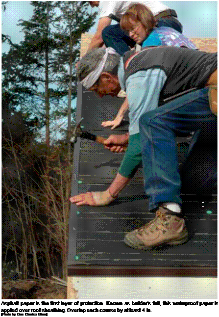
Roll out the felt paper

Felt paper, sometimes called tar paper or builder’s felt, is the first protective layer installed over roof sheathing. This material has evolved in a fashion similar to that of a candy bar. In the

old days, you could buy a good-size candy bar for a nickel. Today, you get a much smaller bar at a higher price. Similarly, the felt paper avail­able today is much lighter, even though it’s still sold as 15-lb. and 30-lb. felt. I like to use 30-lb. felt for the underlayment because it provides extra protection and the cost difference isn’t that great. Roofing felt has horizontal lines marked on it. Follow a line that provides a minimum 4-in. lap as you roll one row over another.

Подпись:Подпись: Cut elliptical holes in felt flashing. When you need to flash around a vent pipe, fold the felt in half and cut out half of an ellipse with a sharp utility knife. Because of the roof's slope, the hole is shaped more like an ellipse than a circle. The steeper the slope, the longer the ellipse. Follow nailing guidelines

Some builders like to snap a chalkline on the sheathing 36 in. up from the edge of the gutter or fascia board and lay the first roll of felt to that line. This makes the roll lay down straight. Alternatively, you can hold the felt flush with the edge of the roof. Unroll the felt flat (with no bumps or wrinkles) and tack it down with roof­ing tacks. A roofing tack is a small nail with a large plastic button (generally green, orange, or red) on top (see the photo above). Or you can use a pneumatic nailgun to nail these plastic buttons in place. Stepping on felt that is not nailed well can cause you to slip off the roof, so use plenty of roofing tacks (6 in. o. c. at the
bottom and ends and 10 in. o. c. from top to bottom every 24 in. o. c. across the roof). Roofing tacks hold the felt in place, which is especially important if the roof won’t be shingled for several days. Pick up any tacks that fall to the ground so that no one steps on them. Finally, trim the felt flush with the gable ends.

Whether you are tacking down roofing felt or nailing on shingles, it’s important to consider whether the nails can be seen from below. When the eaves around the house are open (no soffit), a long nail penetrates the roof sheathing and is visible to anyone who looks up. Hundreds of shiny nails sticking through the plywood or OSB is unattractive. Therefore, when tacking felt around the perimeter of the roof, take care to nail the tacks into the barge rafters and gable-end rafters—not just through the sheathing into the air. When nailing shingles, use 5/s-in. nails at the gable overhangs and eaves. When working over the house frame, nails that penetrate the sheath­ing in the attic are not a problem.

Cutting into a Concrete Floor

To enlarge an existing load-bearing pad or create one where none was, you may need to cut through a concrete floor. Depending on the condition and thickness of that floor, the job will range from nasty to horrible. Cutting concrete is noisy, dirty, and dangerous; and the tools are heavy and unpredictable. Wear safety glasses, gloves, hearing pro­tectors, and a respirator mask. Adequate ventilation and lighting are a must.

If the floor was poured before the 1950s, you’ll likely find that it is only 3 in. or 4 in. thick and is without steel reinforcing. The floor may also be badly cracked.

In this case, you can probably break through it with a pickax, but to minimize floor patching later, rent an electric concrete-cutting saw with a diamond blade to score around the opening. Then finish the cut (the saw – blade rarely cuts all the way through) with a hand sledge and a chisel.

Be advised, however, that a concrete-cutting saw cuts dry and thus throws up an extraordinary amount of dust. Therefore, you may need to seal off the basement with plastic barriers and then spend an hour vacuum­ing afterward. Alternatively, you can rent a gasoline – powered wet-cut saw, which keeps down the dust but fills the basement with exhaust fumes. And, if the con­crete floor is a modern slab, 5 in. thick and reinforced

with rebar, you can spend a day accomplishing very little. Well. . . you get the picture.

Fortunately, for a few hundred bucks you can hire a concrete­cutting subcontractor to cut out a pad opening in about an hour. (Don’t forget to allow for the thickness of the form boards when siz­ing the opening.) The subcontractor can also bore holes needed for drainpipes and such.

Подпись: Before adding a girder to correct springy floors, go under the house and see if there's solid blocking or cross bridging between joists. If not, add it, and that may be all you'll have to do to stiffen the floors. If floors sag between joists, the subflooring may be too thin. 1111 Подпись:

under the post (a dab of silicone caulking will hold it in place while you plumb and position the post); then lower the jack so the new post bears the load. Or replace the wooden post with a preprimed metal column. However, if basement floors are wet periodically—suggested by sedi­ment lines along the base of walls—build up or replace the existing pad with a taller one to ele­vate the base of the post. Add a sump pump, too, as explained on p. 224.

Replacing pads. Replace concrete pads that are tilting or sinking because they are undersize for the loads they bear. Likewise, you’ll need to pour a new pad, if there was no pad originally and an overloaded post punched through the concrete floor. Pads for load-bearing columns should always be separated from floors by isola­tion joints.

Load-bearing pads should be 24 in. by 24 in. by 12 in. deep, reinforced with a single layer of No. 4 (12-in.) rebar arranged in a tic-tac-toe grid. Pads supporting a greater load (such as a two – story house) should be 30 in. by 30 in. by 18 in. deep, with two layers of no. 4 rebar; in each layer, run three pieces of rebar perpendicular to three other pieces. In either configuration, keep the rebar back 3 in. from the edges of the pad.

Line the forms with sheet plastic so that the water in the concrete won’t drain into the soil and weaken the pad. (Plastic also prevents soil moisture from later migrating through the pad and rotting the post.) If you carefully level the tops of the form boards and screed off the con­crete to them, the top of the pad will be level as well. Allow the concrete to cure before putting weight on it: 3 days minimum; 7 days recommended.

ADDING A GIRDER

Adding a girder beneath of a run of joists short­ens the distance they span, stiffens a springy floor, and reduces some loading on perimeter foundations. If your floors are springy and joists exceed the following rule-of-thumb lengths, con­sider adding a girder.

JOIST SIZE____ TYPICAL SPAN (ft.)

2 x6 8

2 x8 10

2×10 12 2×12

An engineer can size the girder for you.

"Beam Span Comparison,” on the facing page, shows maximum spans for built-up girders in two-story houses.

Ideally, the new girder should run beneath the midpoint of the joist span, but if existing ducts or drainpipes obstruct that route, avoid them by shifting the girder location a foot or two. Once you locate the girder, snap a chalkline to mark its center, and plumb down from that to mark posi­tions for pads and posts. Place posts at each end of the girder and approximately every 6 ft. along its length. If you create a girder by laminating several 2xs, keep at least one member of the "beam sandwich” continuous over each post.

Size and reinforce pads as described in the preceding section. After the pad’s concrete has cured 1 week, bring in the girder or laminate it on site from 2-in. stock. Prescribed widths for built-up girders are usually three 2x boards (4И in. thick when nailed together). For built-up girders and beams, the Uniform Building Code recommends the following nailing schedule:

20d nails at 32 in. on center at the top and bot­tom and two 20d nails staggered at the ends and at each splice.

Whether solid or laminated, if the girder has a crown, install it crown up. Installing a new girder is essentially the same as positioning a temporary shoring beam, except that the girder will stay in place. Have helpers to raise the girder and sup­port it till permanent support posts are in place. Properly sized, the pad will have more than enough room for jacks and posts, so place jack­ing posts as close as possible to the permanent post’s location. Raise the girder approximately 18 in. higher than its final position, to facilitate insertion of the new posts.

STEEL BEAMS

If there’s limited headroom or clearance under the house, steel beams provide more strength per equivalent depth than wood beams. For steel beams, hire an engineer to size them and a spe­cialist to install them: Steel I-beams are expen­sive and heavy, and they can be problematic to attach to wood framing, without special equip­ment to drill holes, spot-weld connectors, and so on. For commonly available sizes and some sense of the weights involved, see "Steel I-Beams,” on p. 53.

Contaminant Sampling and Analysis

Teresa Leitao*, Andrew Dawson*, Torleif Bakken, Mihael Brencic, Lennart Folkeson, Denis Francois, Petra Kunmska, Roman LiCbinsky and Martin Vojtesek

Abstract This chapter presents a general overview of procedures and methods for sampling and analysis of contaminants in water and soil in the road environment. The chapter concerns the water and seepage in road structures under the influence of traffic loading, and in the adjacent ground extending to the water table where contaminant seepage is of concern. The text gives an introduction to this subject and guides the reader to relevant literature with detailed information about practices of sampling and analysis. The chapter in divided into five main sections: principles of data collection and storage, sampling design, water and soil sampling procedures, and in-situ and laboratory measurements and analyses.

Keywords Road contaminants ■ data collection and storage ■ sampling design ■ in-situ and laboratory analysis ■ water ■ soil

7.1 Introduction

The purpose of contaminant sampling and analysis is mainly to characterize a specific road in terms of its runoff characteristics and the water percolating vertically through the road structure, as well as the existing state of quality of the adjacent water and soil. Sampling and analysis can also be performed to identify a specific pollution episode. The environmental compartments, usually considered as being potentially affected, comprise surface waters, groundwater, soil and soil water. To­gether they can give a global picture of contaminant dispersion and pathways after entering the soil (see Chapter 6). [16] [17]

Inlet and Outlet Control

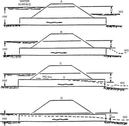
There are two types of flow in culverts: inlet control and outlet control. Accurate pre­diction of the condition of flow is difficult, and an assumption of the most conservative control may at times be warranted. Figures 5.12 and 5.13 depict several conditions of inlet and outlet control.

For inlet control, the discharge capacity is controlled at the upstream or inlet end. Factors that have an effect on the culvert performance under this condition are the headwater elevation, the inlet area of the barrel, and the inlet configuration. For outlet control, the discharge is controlled at the downstream end. Additional factors affecting performance under this condition include the tailwater elevation, characteristics of the culvert barrel (slope, length, roughness, shape, and cross-sectional area), and the outlet configuration.

With inlet control, the culvert usually flows only partially full; the roughness, slope, length, and outlet condition of the culvert do not affect the discharge capacity. The headwater depth is measured from the invert. The inlet area is generally the same as the cross-sectional area of the barrel. However, when tapered or beveled inlets are utilized, the face area is enlarged and the control area is at the throat. The efficiency of a culvert is greatly affected by the inlet configuration and may be heightened by the use of beveled edges and tapered inlets, which reduce the contraction of the flow, thereby effectively enlarging the face area. Bevels are large chamfers or rounded corners at the inlet. Tapered inlets may be tapered either at the sides or at the bottom (slope tapers). Either type will increase the flow capacity or, conversely, decrease the head­water elevation for a given capacity. Prior to their use, the cost of the improved inlet should be compared with the savings from the use of a smaller barrel.

Inlet and Outlet ControlINLET SUBMERGED

MEDIAN

DRAIN

HW fv——————————————–

Подпись: WATER SURFACE
Inlet and Outlet Control
Подпись: INLET UNSUBMERGED
Подпись: MW
Подпись: WS

INLET SUBMERGED

FIGURE 5.12 Illustration of culvert under inlet flow control. (From Highway Drainage Guidelines,

Vol. IV, American Association of State Highway and Transportation Officials, Washington, D. C., 1999, with permission)

Inlet and Outlet Control Inlet and Outlet Control Подпись: Ц2 2g Подпись: (5.21)

The coefficient ke, which represents the efficiency of the culvert inlet, is listed in Table 5.9 for many different designs. It may be used to calculate the head loss at the entrance from the equation

where He = entrance head loss, ft (m) ke = energy coefficient V = velocity, ft/s (m/s)

g = acceleration of gravity, 32.2 ft/s2 (9.8 m/s2)

Extensive research by the Bureau of Public Roads and later work by the Federal Highway Administration established a series of equations for determining the headwater at a culvert entrance. In addition, a series of nomographs for the solution of the equa­tions for the various culvert materials were prepared. This information is available in the FHWA publication HDS 5, “Hydraulic Design of Highway Culverts.” The charts in HDS 5 are arranged in groups according to shapes and materials. The charts include the types, materials, and inlet configurations listed below:

1. Circular concrete pipe with both square-edge and groove-edge inlets

2. Circular corrugated metal pipe

Inlet and Outlet Control

FIGURE 5.13 Illustration of culvert under outlet flow control. (From Highway Drainage Guidelines,

Vol. IV, American Association of State Highway and Transportation Officials, Washington, D. C., 1999, with permission)

3. Concrete boxes with headwalls or wingwalls, with or without beveled or chamfered inlets

4. Corrugated metal box culverts with earth, concrete, or metal inverts

5. Horizontal and vertical elliptical concrete pipe with both square-edge and groove – edge inlets

6. Corrugated metal pipe-arch

7. Corrugated metal structural plate pipe-arch with 18-in (450-mm) and 30-in (750-mm) corner radii

8. Corrugated metal arch culverts with earth, concrete, or metal inverts

9. Various shapes of structural plate long-span culverts

10. Various shapes of culverts with slope-tapered and side-tapered improved inlets

TABLE 5.9 Entrance Loss Coefficients for Culverts under Outlet Control, Flowing Full or Partly Full

Type of structure and design of entrance

Coefficient k

e

Pipe, concrete

Projecting from fill, socket end (groove end)

0.2

Projecting from fill, square-cut end

0.5

Headwall or headwall and wingwalls

Socket end of pipe (groove end)

0.2

Square edge

0.5

Rounded, radius = (Yn)D

0.2

Mitered to conform to fill slope

0.7

End section conforming to fill slopes*

0.5

Beveled edges, 33.7° or 45° bevels

0.2

Side – or slope-tapered inlet

0.2

Pipe, or pipe-arch, corrugated metal

Projecting from fill (no headwall)

0.9

Headwall or headwall and wingwalls, square edge

0.5

Mitered to conform to fill slope, paved or unpaved slope

0.7

End section conforming to fill slope*

0.5

Beveled edges, 33.7° or 45° bevels

0.2

Side – or slope-tapered inlet

0.2

Box, reinforced concrete

Headwall parallel to embankment (no wingwalls)

Square-edged on 3 edges

0.5

Rounded on 3 edges to radius of >12 barrel

dimension, or beveled edges on 3 sides

0.2

Wingwalls at 30° to 15° to barrel

Square-edged at crown

0.4

Crown edge rounded to radius of >12 barrel

dimension, or beveled top edge

0.2

Wingwall at 10° to 25° to barrel

Square-edged at crown

0.5

Wingwalls parallel (extension of sides)

Square-edged at crown

0.7

Side – or slope-tapered inlet

0.2

*“End section conforming to fill slope,” made of either metal or concrete, is the section commonly available from manufacturers. From limited hydraulic tests it is equivalent in operation to a headwall in both inlet and outlet control. Some end sections, incorporating a closed taper in their design, have a superior hydraulic performance. These latter sections can be designed using the information given for the beveled inlet.

Source: From Hydraulic Design of Highway Culverts, HDS 5, FHWA, with

permission.

The charts may also be used for plastic pipes. The appropriate chart selection should be based on a comparative entrance configuration and barrel roughness.

The reader is urged to obtain a copy of this document since it is the primary method used for culvert design and the nomographs it contains are an indispensable design aid.

If a culvert operates under outlet control with a free-water surface along the entire length of the culvert, the nomographs should not be used. In lieu of the nomographs, a backwater calculation should be performed.