STEP 9 Shingle the Roof

Back in the days when 1 was a roof shingler, I hardly ever saw asphalt or fiberglass (compo­sition) shingles. Being a shingler meant work­ing with wood shingles. Now in most parts of the country, I see wood shingles used more often on the sides of buildings than on roofs. Composition shingles are more popular because they are faster to install and more resistant to lire.

Give some thought as to the color and style ol the shmules that vou want on your house. Л new stvlc of architectural shingle that casts a

V О

shadow has become popular. Light-colored

HOW TO ORDER VINYL SIDING

Horizontal siding panels are usually 12 ft. 6 in. long, though some companies make longer panels. Siding is sold by the square, or the number of panels needed to cover 100 sq. ft. To estimate how many squares of siding you’ll need, calculate how many square feet of wall surface you need to cover, add 10 percent for waste, then divide by 100.

Order enough starter strips to go around the entire building; these typically come in 10-ft. lengths. You’ll also need trim for each inside and outside corner. You can order trim pieces that are the same color as the siding or use a contrasting color, as we did on this house.

If the windows didn’t come with an integral J-channel, or chan­nel surround, then order enough J-channel to cover the top and the sides of all the windows and doors. J-channel is also used along the rake and soffit, as shown on p. 152.You also need to order enough undersill trim to go below each window and to cap the top edge of the last piece of wall siding on the eave walls, which is how they are often finished.

Large-head, 11/2-in. to 2-in. galvanized nails are used to attach both the siding and the trim. A 50-lb. box should be adequate for a small house. Finally, don’t forget about the vinyl soffit panels for closing in the area under the eaves. As shown in the following pages, soffit panels may require J – or F-channel trim.

SAFE SCAFFOLDING KEEPS YOU OUT OF HARM’S WAY

On single-story construction, most scaffold work can be done with good sawhorses and good planks. Make sure the planks you choose have a solid, even grain and small, tight knots. If a plank breaks, a fall of only a cou­ple of feet can put you out of commission for a while. And just because you buy good scaffold planks today doesn’t mean that they will be safe to use a year from now, especially if they’re left out in the elements. I pre­fer to use manufactured decking planks made of steel and aluminum. They are more expensive, but they make a more secure working platform.

When you have to work higher up, you’re better off buying or renting solid-pipe scaffolding. These 6-ft.-high units are easy to set up, and they create a 5-ft. by 8-ft. working platform. Make sure the legs are set on a firm foundation and not just on bare earth. Pipe-scaffolding units can be stacked on top of each other for working on a two-story building. If you will be working more than


10 ft. high, ask for guardrails, which are easy to install and help protect you from an accidental fall.

Some builders like to use pump jacks and ladder jacks as an alternative to pipe scaffolding. Available at most sup­ply houses, these jacks are useful when installing sheath­ing, housewrap, or siding. Used in pairs, pump jacks attach to double 2×4 or single 4×4 (31/2-in.) posts that are held upright with braces temporarily nailed to the roof or to the wall framing. Each pump jack can move up and down on its post to adjust the elevation of the work platform.

If you’re using pump jacks, make sure the units come with a built-in guardrail that protects you from falling backward. Make sure the uprights rest on a solid base and not on bare earth. Ladder jacks are steel brackets that hook on the rungs of ladders. Once the brackets are se­cured to a pair of ladders, you can set planks on the brack­ets. If you want to move up and work at a higher level, you must remove the planks and reposition the brackets.


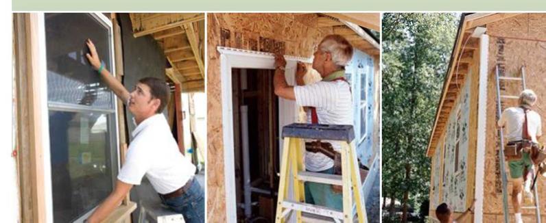
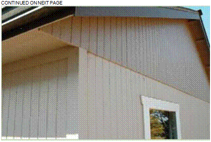
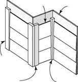
The walls look strange covered with foam boards and wood panels.

Vinyl siding will be a big improvement.

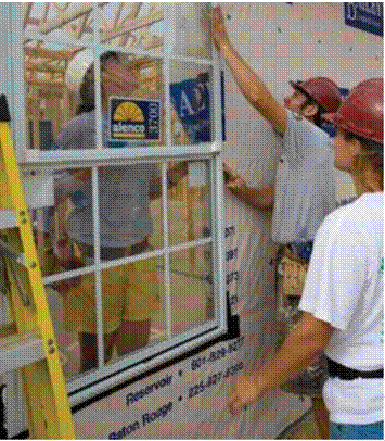
All the windows must be installed before the siding goes on.

It takes teamwork to get the window frame into its opening and centered properly.

Vinyl starter strips and different kinds of trim must be nailed in place before we install the siding panels.


HOW TO ORDER VINYL SIDING

Подпись: ІШІШІШШІІШШШІІШШШШШШШІШШШШШШІІШШШШШІШІШШІШШШШШШШІШІШШШІІШШШШІШІШІШШІІІ Подпись: HABITAT HELPS NEW HOMEOWNERS CONTINUE LEARNING Providing a family with four walls and a roof is just the first step in helping them get established. Here at the Twin Cities' affiliate, we also aim to equip families with knowledge, so that they become successful homeowners. Because Habitat families are first-time homebuyers, most are unfamiliar with the basic maintenance, repair, and budgeting responsibilities that come with homeownership. To bridge this information gap, we provide more than a dozen different classes. Many classes emphasize that “an ounce of prevention" helps protect a family's investment and reduces long-term costs. Basic maintenance classes describe how a house works from top to bottom and explain how (and why) to turn off outdoor faucets, clean out window wells, drain sediment from the water heater, test fire alarms, and check for excessive moisture in the attic. Habitat homebuyer classes cover more than just caring for the physical house, however. Three money-management classes cover everything from basic budgeting to the pitfalls of credit cards to teaching children how to use money wisely. Other classes cover topics such as poisonous household products, city ordinances that affect property, block clubs, safety, and crime prevention. Because Habitat has a commitment to environmental stewardship, our classes also cover recycling; ecologically friendly (and economical) practices, such as making cleaning products from natural ingredients; and energy and resource conservation. These practices often seem like common sense to homebuyers who have come from countries without the wealth of natural resources we enjoy here. And while they learn new ways of doing things in class, Habitat families often share old traditions as well. —Cheryl Winget і и їм їм MI и їм їм MI и їм їм MI и їм їм їм MI и їм їм MI и їм їм MI и їм їм їм MI и їм їм MI и їм їм MI и їм їм MI и їм їм їм MI и їм їм MI и їм їм MI и їм їм MI

Exterior trim

Aluminum-clad exterior trim goes well with vinyl siding because, like vinyl, it’s also a no­maintenance finish treatment. Aluminum sheets have a factory-applied finish and come on large rolls in various widths. Often referred to as coil aluminum, this sheet material is bent at the job site to fit around exterior trim boards.

To prep for this treatment, rough fascia boards (also called gutter boards) are nailed to the ends of the roof trusses and to the rafter tails on the roof extension above the side door (see the photo on p. 154). Some of these trim details are covered in Chapter 5 and should be com­pleted before the roof is sheathed and shingled. Other trim details, such as the boxed gable-end return shown on p. 173, can be done as the alu­minum cladding goes on.

STEP 1 INSTALL THE REMAINING SHEATHING AND THE ROUGH EXTERIOR TRIM

STEP 1 INSTALL THE REMAINING SHEATHING AND THE ROUGH EXTERIOR TRIMПодпись: Furring strips keep the siding away from the wall. This creates a drainage plane helping to keep both siding and OSB sheathing dry.Straight courses of finish siding and sharp-looking exterior trim depend on good prep work on the sheathing and exterior trim surfaces that will be covered with aluminum cladding. A good deal of wall sheathing will already be done at this stage. Now that finish siding is about to be installed, it’s important to make sure the wall surfaces are flat and free of gaps that will cause dips or irregularities when the vinyl is installed. When installing foam sheathing, you can sheathe right over window and door openings, then use a handsaw to cut out the foam from the opening (see the photo on p. 109).

Подпись:

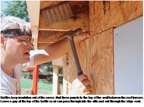
If necessary, install wood sheathing or foam board over any unsheathed areas on which siding will be installed. These areas include the rim joist and headers above windows and doors. Along eave walls, it’s also essential to extend the sheathing between the roof trusses above the top plate of the exterior wall, as shown in the photo at right. This additional sheathing acts as a baf­fle, preventing attic insulation from spilling out into the eaves. Cut each OSB panel so that there are a couple of inches of open space between the top edge of the panel and the top edge of the roof trusses. This clearance is essential for good ventilation; it allows air to be drawn through the soffit vents and into the attic space.

Roofing

A well-sloped roof with a sizable overhang is preferable to a flat or low-sloped roof for the following reasons:

The roof overhang plays an important role in protecting the walls and foundation from water damage by directing water away from the building.

Inert roofing materials are readily avail­able and are standard products for sloped – roof construction, while they are an exception in flat or low-sloped residential roof construc­tion.

Sloped roofs shed water quickly, whereas water will puddle and linger on poorly con­structed flat roofs.

Flat roofs have a higher failure rate and shorter life expectancy, which may lead to devastating mold problems.

Overhangs can be sized to suit the solar conditions in your region, providing shade in the summer while allowing maximum heat entry in the winter.

The great aqueducts of Roman cities

Water is at the very top of the scale of values of Roman civilization. Water “not only services and satisfies the needs of the public, but also satisfies their pleasures.”[213] Numerous public fountains flow constantly in the city of Rome. Some individual users are granted a special concession for drawing water. Under the Republic this service is paid for, and it later becomes a free service granted by the Emperor. But the thermal baths, becoming widespread from the period of Augustus, are the most important water users.

The great aqueducts of Roman cities

Figure 6.2 A Roman public fountain at Ostia (photo by the author)

When water is in short supply, basic needs (e. g. public fountains, and flushing of sewers to maintain hygiene) must take priority over pleasure use. The architect Vitruvius describes a design giving priority to the public fountains (see Figure 6.4):

When they (the channels) are brought home to the walls of the city a reservoir (castellum) is built, with a triple cistern attached to it to receive the water. In the reservoir are three cisterns of equal sizes, and so connected that when the water overflows on either side, it is discharged into the middle cistern, in which are placed pipes for the supply of the public fountains; in the second those for the supply of the baths, thus affording a yearly revenue to the people; in the third, those for the supply of private houses. This is to be so managed that the water for pub­lic use may never be deficient.”[214]

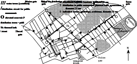
There remain only a few traces of the Roman distribution networks, one of the few being at Pompeii (Figure 6.3) whose castellum corresponds rather well to the scheme described by Vitruvius.[215]

The great aqueducts of Roman cities

Figure 6.3 Water in a Roman city, Pompeii. The Figure shows the map of public fountains, the layout of water supply to public monuments and the intermediate works in the various circuits: elevated reservoirs and distribution towers. The distribution towers are fitted with a small elevated reservoir, whose level makes it possible to adjust the pressure in the downstream installations. The castellum of the Vesuvius gate (Figure 6.4) is situated at the highest point of the city, receiving its water from the aqueduct of Serino (Escheback, 1979-1983). In August 79 AD Pompeii is destroyed by an eruption of Vesuvius.

water passes over barriers of different elevations:

^ fine grid щґ f\

3

Y:icoarse grid/v-;<

1

Подпись: end point of the aqueduct: canal 1.3 m deep and 0.55 m wide

Figure 6.4 Castellum schematic at the Vesuvius gate of Pompeii, terminal point of the aqueduct, feeding the three distribution circuits. Water to these three circuits is supplied by overflow weirs at different levels, thus providing for a distribution hierarchy as recommended by Vitruvius.

The great aqueducts of Roman cities

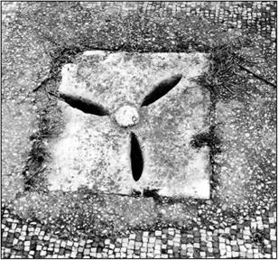
Figure 6.5 A drainage inlet at Ostia (photo by the author).


The great aqueducts of Roman cities

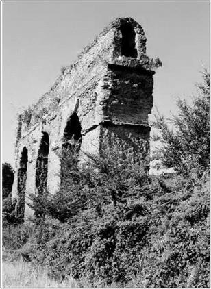
The great aqueducts of Roman citiesFigure 6.6 The Anio Novus, one of the greatest Roman aqueducts, supported by arches in the Anio valley, between Tivoli and Castel madama. The canal, still lined with opus signinum, is well conserved. This aqueduct was built in 52 AD near the end of the reign of emperor Claudius (who also was responsible for the Aqua Claudia aqueduct), and is some 87 km long. It carries water captured from the Anio river, in the Sabine mountains near Subiaco.

(photo by the author).

As we can see through these examples, Roman cities benefit from an abundance of water, a bounty unequalled until the 20th century AD. Creation of this abundance requires that water be brought to the cities from springs or other supply points, where in general a storage reservoir is built, serving also as a settling or clarifying basin. The water is conveyed by aqueducts to the city’s castellum, or water tower, from which emanate the local distribution circuits. The aqueducts are often lasting monuments in which the Romans take great pride. A highly placed Roman official, whom we introduce later on, even compares these aqueducts to the Pyramids and to Greek temples:

“With such an array of indispensable structures carrying so many waters, compare, if you will, the idle Pyramids or the useless, though famous, works of the Greeks!”[216]

FIBER-CEMENT SIDING

Fiber-cement siding has been around a long time. The first house I worked on in the late 1940s was covered with fiber – cement siding. It was a bit brittle but just about indestruc­tible. It fell out of favor because it was hard to work with and full of asbestos, whereas high-quality wood siding was inexpensive and becoming widely available.

Times have changed. Today, wood siding is expensive and often lacking in quality. Modern fiber-cement siding, on the other hand, contains no asbestos and offers all of its old ad­vantages and a few new ones, too. I like it because it is simple to install, holds paint well, is fire resistant, is easy to trim out, and won’t decay, rust, or mold. And if that wasn’t enough, it has a 50-year guarantee! Like vinyl, it’s fairly easy to work with, thanks to the new cutting and nailing equipment avail­able today. Unlike wood, it doesn’t cup, curl, or attract ter­mites. Unlike vinyl, it doesn’t burn, melt, expand, or contract.

Once you learn a few basic techniques, such as how to cut and nail it, fiber-cement siding is easy to install and goes on one plank at a time. The siding can sometimes be nailed directly to studs that have been covered with housewrap. In high wind and earthquake areas, siding often has to be nailed on walls that have been sheathed with OSB panels. These

FIBER-CEMENT SIDING

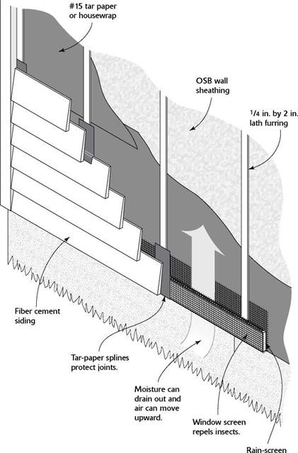
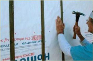
Space can be created between the wall sheathing and the siding either by using a rain screen or by nailing lath strips to each stud. This space allows moisture to drain and protects wood from rot or mold. [Photo by Don Charles Blom]

FIBER-CEMENT SIDING

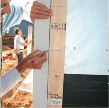
Layout to set the levels for horizontal siding can be done with a story pole. Use the story pole to mark the siding layout on doors, windows, and trim all around the house. [Photo by Don Charles Blom]

OSB panels add lateral and structural strength to a building. In such cases, care must be taken to insure that moisture passing through the walls does not settle on the OSB and cause rot. This problem can be dealt with by creating a space between the siding and the OSB. There are different ways to create this buffer zone. To learn how to approach this part of the project, refer to the manufacturer’s product and installa­tion information, which is comprehensive and extremely use­ful (see Resources on p. 279).

Fiber-cement clapboard siding comes in various widths that are usually 12 ft. long and 5/i6 in. thick. Both smooth and wood-grain textures are available. For best results, order the siding pre-primed on both sides. You can also purchase 4-ft. by 8-ft. panels that have vertical grooves likeTl-11, or smaller panels that have a shingle pattern. For best results, order the siding pre-primed or with a permanent color already on the siding. After it has been delivered to the job site, keep it covered with a tarp whenever you’re not using it to mini­mize moisture absorption. Store the siding flat and level, too, so it doesn’t break or warp.

Cutting tips

Fiber-cement siding can be cut with a regular circular saw and a conventional carbide blade, but a diamond-tipped ma­sonry blade with four to six teeth works much better and is probably cheaper in the long run. The biggest problem with
cutting fiber-cement with a power saw is that it creates a lot of dust. Be sure to wear a good dust mask and follow the manufacturer’s recommendations to avoid unnecessary ex­posure to silica, which can damage your lungs.

I prefer to use a set of electric fiber-cement siding shears, a power tool designed specifically for this job (see Resources on p. 279).The shears cut cleanly, don’t create any dust, and can be used for both straight and curved cuts. For small holes, such as those for exterior electrical outlets, use a jigsaw with a carbide-tipped blade. Cut round holes for pipes with a carbide – tipped hole saw mounted in a heavy-duty, two-handled drill.

Corrosion-resistant fasteners

Most companies guarantee their fiber-cement siding for 50 years. Therefore, it will last a long time—provided it’s properly attached with high-quality, corrosion-resistant nails. I generally use regular 2-in.-long, hot-dipped galva­nized nails. If I’m working near the ocean or another area with high humidity, I often use stainless-steel nails.

For the most part, builders use pneumatic nailers to at­tach fiber-cement siding to walls. I’ve found that a regular pneumatic nailer works better than a roofing nailer (see Resources on p. 279). Make sure that the pressure is set correctly once you get started so that you don’t overdrive the nails. Nailguns these days often have a depth gauge to ensure that nails are driven flush with the surface. And there are special coil nailguns that have been developed specifically for siding. Fiber-cement siding can be nailed by hand, but you may need to predrill the nail holes to keep from breaking off the end of the plank. It’s a good idea to have a pocket full of felt strips (3 in. by 8 in.). Each time you have two pieces of siding meet at a butt joint, slip a piece of felt behind the joint and let it lap down on the lower course about an inch. This will help prevent water from entering at the joint.

Trim details

As with wood siding, trim for fiber-cement siding is usually installed first, and then the siding panels are butted against

Siding can be highlighted by using different paint colors. The con­trast adds to the beauty of the building. [Photo by Don Charles Blom]
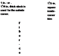
it. Fiber-cement trim is available for inside and outside corners, doors, and windows, as well as for covering fascia boards and soffits. The illustrations on p. 152 show a few of the trim details available. These same details also work for wood clapboards and wood shingle siding. The trim should be fairly thick—either 5/4 (11/4 in. thick) or 2x—in order to stand proud and cover the ends of the siding.

At the outside corners, the siding can butt against the cor­ner boards or be covered with aluminum corner pieces (called siding corners).These pieces have been used for many years as trim for wood siding and work just as well with fiber-cement siding. The siding is installed first and stopped exactly at the corner. After all the siding is in place, the siding corners can be slipped under each course. A flange at the bottom of the corner hooks a row of siding and a 6d or 8d galvanized nail is driven through a hole in the top to hold it in place.

Installing siding panels

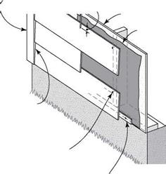
Подпись: CONTINUED ON NEXT PAGE The installation details for fiber-cement siding are similar to those for wood clapboards. The bottom-most course of siding rests on a 5/i6-in.-thick, 1f/2-in.-wide starter strip cut from the siding or from pressure-treated wood. The bottom edge of the first course should lap about 1 in. below the top of the founda – tion. To install subsequent courses, follow the manufacturer’s recommendations for overlapping and nailing. After you know the amount of reveal the siding will have, you can establish the height of each course. For example, a typical lap on 8f/4-in.-wide

FIBER-CEMENT SIDING CONTINUED

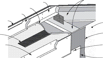
SOFFIT, SIDING, AND FRIEZE-BOARD DETAILS


FIBER-CEMENT SIDING

Drip

edge


Sheathing Housewrap Blind nail


Screened
vent


Frieze board


FIBER-CEMENT SIDING
FIBER-CEMENT SIDING

Door trim


FIBER-CEMENT SIDING
FIBER-CEMENT SIDING

Fiber-cement or PT starter strip, 5/16 in. thick and 11/2 in. wide


FIBER-CEMENT SIDINGFIBER-CEMENT SIDINGFIBER-CEMENT SIDING

FIBER-CEMENT SIDING

siding is 11/4 in., which leaves a 7-in. reveal. This reveal can be marked on each piece of corner trim and on every door and win­dow all around the house by using a story pole. A reveal can be adjusted up or down slightly (up to V2 in.) in order to fit siding pieces around door and window openings, and to maintain a uniform distance between the top of the wall and the uppermost siding course. To make sure the last course of siding will be uni­
form in width, measure down from the top of the wall frequently (every other course or so) and fine-tune the reveal, if necessary.

You can mix and match siding to add a bit of style to a build­ing. Gable ends can be sheathed with a different type of siding than the walls. Tl-11 in the gable end, for example, will contrast with lap siding on the walls. Contrasts can be made even greater by painting the walls a different color than the gable end.

FIBER-CEMENT SIDING Подпись: iiiiiiiiiiiiiiiiiiiiii
Подпись: FIBER CEMENT SIDING COMPONENTS AND INSTALLATION DETAILS

other components, such as vents, electrical out­let covers, and special exterior trim. It’s smart to get an overview of the full range of com­patible products before you order siding. Go online to visit manufacturer’s websites or call to request product information (see Resources on p. 279).

SAFETY SYSTEMS

Roger L. Brockenbrough, PE.

President

R. L. Brockenbrough & Associates, Inc.
Pittsburgh, Pennsylvania

One of the most important and most challenging aspects of highway engineering is designing to enhance life safety. This chapter focuses on roadside safety, which encompasses the safety of vehicles that leave the roadway and shoulder.

This material is based largely on the publication of the American Association of State Highway and Transportation Officials (AASHTO), Roadside Design Guide (2002, 2006), which was developed by the AASHTO Subcommittee on Design, Task Force for Roadside Safety, currently under the chairmanship of Keith A. Cota. Made up of about 20 highway engineers with diverse experience, the task force maintains and updates a synthesis of current information and operating practices to serve as a comprehensive guide to individuals and agencies in developing standards and policies. Their contribution to promoting highway safety is gratefully acknowledged.

Typical hazard functions

The failure rate for many systems or components has a bathtub shape, as shown in Fig. 5.8, in that three distinct life periods can be identified (Harr, 1987). They are the early-life (or infant mortality) period, useful-life period, and wear-out – life period. Kapur (1989b) differentiates three types of failure that result in the bathtub type of total failure rate, as indicated in Fig. 5.8. It is interesting to note that the failure rate in the early-life period is higher than during the useful-life period and has a decreasing trend with age. In this early-life period, quality failures and stress-related failures dominate, with little contribution from wear-out failures. During the useful-life period, all three types of failures contribute to the potential failure of the system or component, and the overall failure rate remains more or less constant over time. From Example 5.1, the exponential distribution could be used as the failure density function for the useful-life period. In the later part of life, the overall failure rate increases with age. In this life stage, wear-out failures and stress-related failures are the main contributors, and wear-out becomes an increasingly dominating factor for the failure of the system with age.

Quality failures, also called break-in failures (Wunderlich, 1993, 2004), are mainly related to the construction and production of the system, which could be caused by poor construction and manufacturing, poor quality control and workmanship, use of substandard materials and parts, improper installation, and human error. Failure rate of this type generally decreases with age. Stress – related failures generally are referred to as chance failures, which occur when loads on the system exceed its resistance, as described in Chap. 4. Possible causes of stress-related failures include insufficient safety factors, occurrence

Подпись: Figure 5.8 Bathtub failure rate with its three components.

of higher than expected loads or lower than expected random strength, misuse, abuse, and/or an act of God. Wear-out failures are caused primarily by aging; wear; deterioration and degradation in strength; fatigue, creep, and corrosion; or poor maintenance, repair, and replacement.

The failure of the 93-m-high Teton Dam in Idaho in 1976 was a typical exam­ple of break-in failure during the early-life period (Arthur, 1977; Jansen, 1988). The dam failed while the reservoir was being filled for the first time. Four hours after the first leakage was detected, the dam was fully breached. There are other examples of hydraulic structure failures during different stages of their service lives resulting from a variety of causes. For examples, in 1987 the foundation of a power plant on the Mississippi River failed after a 90-year service life (Barr and Heuer, 1989), and in the summer of 1993 an extraordinary sequence of storms caused the breach of levees in many parts along the Mississippi River. The failures and their impacts can be greatly reduced if proper maintenance and monitoring are actively implemented.

Moist Soil in Crawl Space Causes Ceiling Damage

A 15-year-old single-family residence was pur­chased for year-round occupancy in a popular ski area of Idaho. During the first spring in the home, thefamily noted water dripping from the ceiling of the kitchen. The dripping continued fora couple of days, and then the condition appeared to resolve itself. The family forgot about the problem until it recurred during the spring of the second year. This time they noted a strong, musty odor developing inside the kitchen cabinets. Once again the drip­ping soon stopped, but a few days later mold be­came visible on the kitchen ceiling and inside the upper and lower cabinetry.

Investigation revealed that the soil in the

crawlspace under the kitchen was damp. Be­cause the moisture vapor content of the soil under the home was high, moisture was coming into the home as a soil gas. It was traveling through the ceiling, condensing on the cold underside of the kitchen roof, and freezing. During the spring, the ice block melted into the ceiling space above the kitchen, soaking the gypsum board and insulation. The wet insulation acted like a sponge, holding excess moisture long enough to cause mold growth.

The owner was advised to install a vapor re­tarder on the soil surface of the crawl space. At this point, he admitted with embarrassment that

• Icynene Insulation System:* A low – density, sprayed-in-place modified ure­thane foam insulation that is free of form­aldehyde, fibers, CFCs, and HCFCs and according to the manufacturer has no de­tectable emissions after 30 days. It performs as an air barrier and is vapor-permeable, with an R-value of 3.6 per inch.

• Ultra Touch: A formaldehyde-free natural fiber insulation made mostly of recycled content, with thermal and acoustic per­formance superior to fiberglass batt. No warning labels and no respirator or protec­tive gear necessary for installation. Comes unbacked in 5 A-inch R-i9battsor3y2-inch R-13 batts.

(*Wet-applied insulation must be thoroughly dry prior to application of an air barrier in or­der to avoid trapping excess moisture in the wall cavity.)

Insulation Over Exposed Beam Ceilings

Where structural members of the ceiling are exposed, the air space between the structural members is not available to receive insulation. In flat roof construction, various tapered in­sulation systems are designed to go over the exposed ceiling decking and create a sufficient slope for proper drainage. The less toxic alter­natives tend to be expensive. It may be more cost effective to build cavity area over the ex­isting exposed ceiling and insulate with one of the above-mentioned products.

Insulation Around Doors and Windows

Regardless of the type of construction, the juncture where windows and doors meet the structure is a potential source of unwanted air infiltration and condensation. The industry standard for sealing this gap is to use an ex­pandable urethane foam product.

there had been a layer of plastic on the soil when they had purchased the home. He had noticed damp under the plastic, so he had removed the plastic to allow the soil underneath to dry. Unfor­tunately, the release of the extra soil gas moisture was sufficient to cause water damage and mold growth. Had the owner left the soil gas barrier in place, he could have prevented the mold prob­lems from developing.

Discussion

Mold infiltration in this home originated with ex­cess moisture in the soil, the cumulative effect of several mistakes and building inadequacies.

Better crawl space ventilation would have helped to remove some of the excess moisture. How­ever, because of the extreme cold in Idaho, large amounts of natural ventilation can freeze pipes. Mechanical ventilation would have been a better solution. The roof also lacked sufficient ventila­tion. Well-built homes have multiple controls. In this case the vapor barrier worked well enough to prevent noticeable moisture problems for 15 years. The removal of the barrier by the owner was the straw that broke the camel’s back.

Foam Insulation

The foam may contain toxic chemicals that will outgas in the wet stage but are believed to cure completely after a short time. These foams may also contain hydrochlorofluoro – carbons (HCFCs). Because HCFCs play a role in depleting the ozone layer, the United States is phasing out their consumption by first lim­iting and then ending their production and import in a stepwise fashion, with the even­tual phaseout scheduled for 2030.3

Because polyurethane foams do an excel­lent job of sealing and insulating these gaps, their efficacy must be weighed against their environmental impact. A look at any of the product MSDS sheets will reveal several pet­rochemical-based ingredients that are consid­ered to be toxic. It is possible to lessen the en­vironmental impact by specifying HCFC-free foam. Where the small amount of outgassing from the dried foam is a concern, the foam can be covered, once it has fully cured, with an air barrier material such as aluminum tape. Polyken Tape 337 is an aluminum tape that has been used successfully by some chemi­cally sensitive individuals for this purpose. Since the tape is moisture impermeable, care must be taken not to trap moisture.

The following widely distributed polyure­thane foams do not contain formaldehyde:

• Great Stuff

• Tiger Foam

Alternatives to Foam Insulation

Recently several natural alternatives to poly­urethane foam have become available. Those wishing to avoid synthetic foams may con­sider the following options:

• Custom Woolen Mills: Wool products for home insulation.

• Eco Wool: Wool batting products.

• Florapan: Hempwool insulation, although not available in this country, is used in Eu­rope for this purpose and can be imported.

• Log Home Wool: Sheep wool insulation in batts or rope configuration can be used for sealing around doors and windows.

Air Barriers

Impervious sheeting, applied to the inside face of stud walls behind the finish surface, is often used to block air movement and is mandated by building departments in some localities. In a home built with standard frame con­struction, such a material is also a means of blocking the fumes generated by undesirable building materials in the wall cavity from en­tering the living space. The barrier itself must also be free of noxious odors and emissions. (See the list of suitable air barriers below.)

This method is not intended for use in hot, humid climates, especially where air condi­tioning is used. Because moisture vapor mi­grates from warm to cold, condensation can occur on the insulation side of the barrier, causing hidden water damage and microbial growth. This type of barrier is often used by chemically sensitive individuals as a tempo­rary measure to block fumes emanating from walls, floors, and ceilings in an existing build­ing. A safer method is to create an air barrier that still allows for the transpiration of mois­ture through the wall. This can be achieved by applying the gypsum board in an airtight manner. Refer to Division 9, “Creating an Air Barrier with Gypsum Board,” for the specifics of this application. When a sheet-type air bar­rier is to be applied, use only unbacked insu­lation to avoid creating a double barrier in the wall cavity.

Given the complexities of construction and the number of materials that must be mechan­ically fastened together, it is almost impossible to avoid punctures in air barrier sheeting. The ultimate success of the barrier will depend on the quality control that is exercised during in­stallation and before all finish surfaces are ap­plied.

Air Barrier Installation

The following instructions can be included in specifications for the proper installation of sheet-type air barriers:

• An air barrier shall be applied on the in­side face of studs, joists, or rafters just prior to the application of the interior fac­ing. After applying the acceptable air bar­rier (see list below), seal with 100 percent silicone caulk or foil tape. Staple the bar­rier in pieces that are as large as possible over the insulation and attach them to the window and doorjambs with staples and approved caulk to form a complete seal. Caulk all wall openings such as plumb­ing and electrical boxes. Tape or caulk all seams and joints. Caulk all electrical boxes at the hole where the wire comes through, or purchase gasketed boxes (refer to Division 16 for product infor­mation). Note: This type of installation is not recommended in air conditioned climates.

• Cross Tuff: Cross-laminated polyethyl­ene sheeting. If you specify “for a healthy house,” the manufacturer will incorporate additional processes.

• Dennyfoil:* Virgin kraft paper laminated with foil containing sodium silicate adhe­sive on both sides.

• Reflectix: Foil-faced and – backed over plastic bubbles, especially designed to re­flect heat,

• rFOIL: Reflective foil insulation product with two layers of plastic bubbles with foil in the middle.

• Super R and Tempshield: Radiant barri­ers and reflective insulation.

• Tu-Tuf4 orXF: High-density, cross-lami­nated polyethylene sheeting.

• Tyvek HomeWrap: Housewrap is gener­ally used for exterior applications and is somewhat vapor permeable while highly resistant to air movement. It can be used to create a suitable air barrier for interior use if it is necessary to block wall, floor, or gen­erated fumes in an existing structure.

(*Not suitable for areas that may get wet.)

Pulling Layout from a Corner (16" O. C.)

Pull layout so that sheathing will break in the middle of a joist/stud. Hook tape on the outside edge of rim joist/plate. Pull and locate 16" on tape, then measure back half the thickness of joist/stud (%" for 2x stock) and mark. This puts the layout mark on 15W. Make an X on the correct side of the layout mark to show the location of the joist/stud.

Continue marking in this way for each subsequent 16" space, thus: 3Ш", 47W, 63W, etc. Finish by drawing square lines through the mark.

The reason for subtracting the %" is that the 4′ x 8′ sheathing will be installed from the outside edge of the rim joist/plate, not from the center.

16" O. C. 16" O. C. 16" O. C. 16" O. C,

15У4" , 3Ш" , 47%" , 63%

4′ x 8′ Sheathing

Rim joist/plate