Cumulative hazard function and average failure rate

Similar to the cumulative distribution function (CDF), the cumulative hazard function can be obtained from integrating the instantaneous hazard function h(t) over time as

Подпись: (5.5)Подпись: (5.6)H(t) = f h(t) dt

J0

Referring to Eq. (5.3), the hazard function can be written as

1 d [pf (t)] 1 d [ps(t)]

Ps (t) dt ps(t) dt

Подпись: H(t)
Cumulative hazard function and average failure rate Подпись: Ґ -d [ps(t)] 0 ps(t) Подпись: ln[ ps (t )]0 = ln[ ps (t)] Подпись: (5.7)

Multiplying dt on both sides of Eq. (5.6) and integrating them over time yields

under the initial condition of ps(0) = 1.

Unlike the CDF, interpretation of the cumulative hazard function is not sim­ple and intuitive. However, Eq. (5.7) shows that the cumulative hazard function is equal to ln[1/ps(t)]. This identity relationship is especially useful in the sta­tistical analysis of reliability data because the plot of the sample estimation
of 1/ps(t) versus time on semi-log paper reveals the behavior of the cumula­tive hazard function. Then the slope of ln[1/ps(t)] yields directly the hazard function hit). Numerical examples showing the analysis of reliability data can be found elsewhere (O’Connor, 1981, pp. 58-87; Tobias and Trindade, 1995, pp. 135-160).

Since the hazard function h(t) varies over time, it is sometimes practical to use a single average value that is representative of the failure rate over a time interval of interest. The averaged failure rate (AFR) in the time interval [t1, t2] can be defined as

Cumulative hazard function and average failure rate

/t? h(t)dt

t2 — t1


ln[ps(t1)] – ln[ps(t2)]
t2 — t1


h (t2) – h (tp

t2 — t1


AFR(t1, t2)


(5.8)


Cumulative hazard function and average failure rate

Therefore, the averaged failure rate of a component or system from the begin­ning over a time period (0, t] can be computed as

AFR(0, t) = —lj[p-lt)] (5.9)

The failure rate, in general, has the conventional unit of number of failures per unit time. For a component with a high reliability, the failure rate will be too small for the conventional unit to be appropriate. Therefore, the scale frequently used for the failure rate is the percent per thousand hours (%K) (Ramakumar, 1993; Tobias and Trindade, 1995). One percent per thousand hours means an expected rate of one failure for each 100 units operating 1000 hours. Another scale for even higher-reliability components is parts per million per thousand hours (PPM/K), which means the expected number of failures out of one million components operating for 1000 hours. The PPM/K is also called the failures in time (FIT). If the failure rate h(t) has the scale of number of failures per hour, it is related to the %K and PPM/K as follows:

1%K = 105 x h(t) 1 PPM/K = 1 FIT = 108 x h(t)

Example 5.1 Consider a pump unit that has an exponential failure density as

ft(t) = ke~lt for t > 0, к > 0

in which к is the number of failures per unit time. The reliability of the pump in time period (0, t], according to Eq. (5.1), is

/

TO

ke-kt dt = e-kt

as shown in Table 5.1. The failure rate for the pump, according to Eq. (5.3), is

Подпись: h(t) =ft (t)

ps(t)

which is a constant. Since the instantaneous failure rate is a constant, the averaged failure rate for any time interval of interest also is a constant.

Example 5.2 Assume that the TTF has a normal distribution with the mean /xt and standard deviation at. Develop curves for the failure density function, reliability, and failure rate.

Solution For generality, it is easier to work on the standardized scale by which the random time to failure T is transformed according to Z = (T — /xt)/at. In the stan­dardized normal scale, the following table can be constructed easily:

(1)

z

(2) Ф (z)

(3)

Pf (z) = Ф (z)

(4)

Ps(z)

(5)

h(z)

-t?

S’ ^ II

<

—3.5

0.0009

0.0002

0.9998

0.0009

0.0000018

—3.0

0.0044

0.0014

0.9986

0.0044

0.0000088

—2.5

0.0175

0.0062

0.9938

0.0176

0.0000352

—2.0

0.0540

0.0228

0.9772

0.0553

0.0001106

—1.5

0.1295

0.0668

0.9332

0.1388

0.0002776

—1.0

0.2420

0.1587

0.8413

0.2877

0.0005754

—0.5

0.3521

0.3085

0.6915

0.5092

0.0010184

0.0

0.3989

0.5000

0.5000

0.7978

0.0015956

0.5

0.3521

0.6915

0.3085

1.1413

0.0022826

1.0

0.2420

0.8413

0.1587

1.5249

0.0030498

1.5

0.1295

0.9332

0.0668

1.9386

0.0038772

2.0

0.0540

0.9772

0.0228

2.3684

0.0047368

2.5

0.0175

0.9938

0.0062

2.8226

0.0056452

3.0

0.0044

0.9986

0.0014

3.1429

0.0062858

3.5

0.0009

0.9998

0.0002

4.5000

0.0090000

NOTE : at = 500 hours; h(t) has a unit of failures/h, t = t + atz.

Column (2) is simply the ordinate of the standard normal PDF computed by Eq. (2.59). Column (3) for the unreliability is the standard normal CDF, which can be obtained from Table 2.2 or computed by Eq. (2.63). Subtracting the unreliability in column (3) from one yields the reliability in column (4). Then failure rate h(z) in column (5) is obtained by dividing column (2) by column (4) according to Eq. (5.3).

Note that the failure rate of the normal time to failure h(t) = ft(t)/ps(t) is what the problem is after rather than h(z). According to the transformation of variables, the following relationship holds:

ft (t) = Ф (z)dz/dt = ф (z)/at

Since ps(t) = 1 — Ф^), the functional relationship between h(t) and h(z) canbederived as

h(t) = h( z)/fft

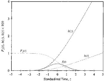
Column (5) of the table for h(t) is obtained by assuming that at = 500 hours. The relationships between the failure density function, reliability, and failure rate for the standardized and the original normal TTF are shown in Fig. 5.7. As can be seen, the failure rate for a normally distributed TTF increases monotonically as the system ages. Kapur and Lamberson (1977) showed that the failure-rate function associated with a normal TTF is a convex function of time. Owing to the monotonically increasing characteristics of the failure rate with time for a normally distributed TTF, it can be used to describe the system behavior during the wear-out period.

Cumulative hazard function and average failure rate

Figure 5.7 Reliability [ps(t)], failure rate [h(t)], failure density func­tion [ ft (t)] for a process/component the TTF of which follows a normal distribution as in Example 5.2.

Manual Placement

In general, most regulations and guidelines do not permit manually placing SMA mixtures; however, there are places where there is no other option but to place the mixture manually (e. g., small and irregular pieces of a roadway) (Figure 10.10). In such cases one should remember not to scatter the mixture with shovels but to carry and lay it down. Compaction should be carried out imme­diately after laying and alignment. Unfortunately such surfaces will differ in structure from adjacent areas spread mechanically, and usually they will be more porous and permeable.

10.2 COMPACTION

Bearing in mind the unique philosophy of designing an SMA aggregate skeleton (see Chapters 2 and 6), SMA compaction may be regarded as the process of form­ing a structure made up of appropriately arranged and interlocked grains filled with mastic. While rolling, the mixture volume is reduced by the tighter arrangement of particles and a decrease in the content of air voids. The binder makes compacting easier. It plays the role of a lubricant, easing the movement of aggregate at that stage of an SMA’s performance.

10.4.1

image102

Types and Number of Rollers

The fact remains that SMA is a difficult mixture to compact, therefore the appropri­ate selection of both the number and type of rollers is of real significance.

Extraction Through Leaching and Percolation Methods

Leaching can be defined as the process by which soluble constituents are dissolved and filtered through the soil by a percolating fluid, while percolation can be de­scribed as the movement of water downward and radially through subsurface soil layers, continuing downward to groundwater (US EPA, 1997 in ADEME, 1999). This led Tas & Van Leeuwen (1995) to define leachate as water or wastewater that has percolated through a column of soil or solid waste in the environment (in ADEME, 1999). The laboratory terminology describes the leaching test as a technique of leaching of solid products by an appropriate solvent in order to ex­tract its soluble fraction (ADEME, 1999). Leaching tests are a kind of extraction technique.

Extraction may be achieved in a number of ways that may be usefully classified as follows:

• Static tests in which the solid specimen is placed in a container with a fixed volume of fluid (leachant) for a certain period of time during which a static equi­librium is reached between the solid and the solution. Such tests are carried out in few hours. Among them one can distinguish:

о Single batch tests in which the leaching solution is unique. Depending on the test method this may, or may not, involved agitation of some form to quickly reach steady-state conditions. Agitated tests focus on measuring the chemical properties of a material-leachant system rather than the physical, rate-limiting mechanisms. In non-agitated extraction tests the material and leachant are mingled but not agitated: these tests measure the physical, rate- limiting mechanisms.

о Serial batch tests in which a series of single leaching tests is carried out on the same solid specimen. Such an approach, by means of a succession of steady states, is intended to exhaust the total amount of removable pollutant or, at least, to monitor change in leaching with volume of water passing. Leaching tests are generally carried out in few hours. They are simpler to apply but are less realistic than the percolation tests described next.

• Dynamic tests in which, in a column, a continuous supply of fresh leachant is passed through the specimen and withdrawn after contact with the solid fraction. Contrary to static tests, they allow assessment of the release as a function of time. After a while a dynamic equilibrium can be reached generating a continuous release. Such tests can last up to several dozens of days. Among them one can distinguish:

о Up-flow percolation tests in which the column is fed from the bottom. This method implies saturated conditions and avoids preferential flows in the col­umn. It may induce pressure migration. The flow through the column is easier to control than in the down-flow percolation test and this means that it is more often used despite being less representative of usual flow conditions in soils. о Down-flow percolation tests in which the leachant flows under gravity through a partially saturated column. These tests are especially useful in studying bio­chemical activity in the vadose zone (Fig. 7.10).

As many soils are rather impermeable, the test is often accelerated by applying large pressure differentials across the specimen of soil, but this reduces the contact time of the water with the solids, so careful interpretation of results is then necessary to ensure that the laboratory result can be applied to the in-situ conditions with meaning.

In each of these tests, the fluid can be water (often distilled and deionised) or it may seek to be representative of in-situ or “worst-case” groundwater (e. g. a weak acid). For static leaching tests, when the water content of the material is too high (sediments, sludge), interstitial water can be recovered by means of a centrifuge.

The centrifuged pellet is then used to carry out leaching. The centrifuge supernatant may also be subjected to testing.

Chemical mechanisms controlling the release of pollutants are dissolution, sorp­tion and diffusion. Diffusion will be controlled by concentration differences and by the total available contaminant content (which can be far lower than the total con­tent). The pH of the material and its environment (in the laboratory: the solvent) are most important as dissolution of most minerals and sorption processes are pH depen­dent. The oxidation/reduction state of the material and its environment influences the chemical form of the contaminant and its solubility. Complexed forms are gen­erally more soluble than non-complexed ones. The presence of solid and dissolved organic matter or humic substances can enhance the leaching. High ion strength of the solution in the material or in its environment generally increases the leaching of contaminants. Temperature increase leads to higher solubility. Lastly, time of con­tact is an important factor for the release amount (van der Sloot & Dijkstra, 2004).

The form of the material (granular, monolithic or cemented) is an important phys­ical factor influencing the transport of a contaminant from the material to the liquid phase. Indeed, the release behaviour of granular materials is percolation (advection) dominated, while for monolithic materials it is diffusion dominated. For granular materials, the particle size determines the distance between the centre of the par­ticle and the surface area of exchange and also, for a given amount of material, the total exchange surface. The latter factor is also important for monolithic mate­rials, considering the shape of the monolith. For granular (in column) and mono­lithic materials, the porosity and the permeability are important factors on release (van der Sloot & Dijkstra, 2004).

Several parameters can be controlled in leaching test protocols in order to high­light different leaching behaviours:

• the relative amount of solvent in contact with the material (expressed in litres/kilogram of dry material, or sometime in litres/sq. metre for monoliths) or the flow through columns;

• the nature of the solvent (generally de-ionised water);

• the time of contact;

• the pH of the solvent (natural or controlled in order to maintain specific values);

• the granular or the monolithic form of the material;

• the crushing of the material to a certain particle size;

• the porosity and the permeability of compacted granular materials implemented into columns; and

• temperature (which generally is ambient temperature or controlled at 20°C).

Table 7.1 presents some examples of typical leach test methods that can be found in the literature. Also listed, for completeness, are speciation tests that aim to sepa­rate out different leaching species.

Vinyl Siding

It’s not difficult to understand the popularity of vinyl siding. It’s affordable, widely available, fairly easy to install, and maintenance-free.

A drawback is that it takes time to learn how to install the vinyl trim pieces that go around doors, windows, and under eaves. Another disadvantage is that in some areas, like the Northwest, vinyl siding needs to be pressure washed yearly to remove fungal growth.

Vinyl windows, vents, soffit material, and other components are designed to be compat­ible with vinyl siding, and there are plenty of
colors, surface textures, and styles from which to choose. You’ll find vinyl siding on compact, affordable houses like the one featured in this book, as well as on expensive custom – built homes.

Horizontal siding is the most popular type of vinyl siding, and most styles are designed to look like wood clapboards. Clapboard widths range from 4 in. to 8 in. Manufacturers of­fer most of their siding with either a smooth surface or a textured, wood-grain finish. When choosing a siding color, bear in mind that it will fade slightly over time. Also, darker siding will absorb more heat and expand more than light – colored vinyl.

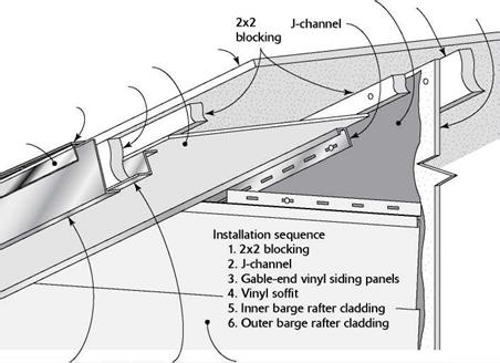
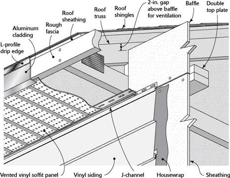
To estimate how much siding you’ll need, refer to the sidebar on p. 154. Keep in mind that when you buy vinyl siding, you’re actu­ally buying a comprehensive system of siding components: siding panels, J-channel, inside and outside corner pieces, and other types of trim designed to simplify the installation and enhance the appearance. Siding manufacturers also make compatible vinyl soffit paneling and

SOFFIT AND SIDING DETAILS

GABLE WALL

Подпись: Roof sheathing Подпись: Housewrap -Подпись: RafterПодпись:Подпись: Outer barge rafter claddingПодпись:Подпись: Vinyl sidingVinyl SidingПодпись:
Подпись: EAVE WALLVinyl SidingBe careful with delicate sheathing. Take aim care­fully when installing foam sheathing. A misdirected hammer blow can easily dent or puncture the foam. Install these insulating panels with broad-head roofing nails or plastic – cap nails. Space the nails about 16 in. apart along the edges and 24 in. apart everywhere else.

Failure rate and hazard function

The failure rate is defined as the number of failures occurring per unit time in a time interval (t, t + At ] per unit of the remaining population in operation at

Failure rate and hazard function
TABLE 5.1 Selected Time-to-Failure Probability Distributions and Their Properties

time t. Consider that a system consists of N identical components. The number of failed components in (t, t + At ], NF (At), is

NF ( At) = N x pf (t + At) — N x pf (t) = N [pf (t + At) — pf (t)]

and the remaining number of operational components at time t is

N(t) = N x ps(t)

Then, according to the preceding definition of the failure rate, the instantaneous failure rate h(t) can be obtained as

h(t) = limA<^0

‘Nf (At )/A t

= limA<^0

N x pf (t + At) — N x pf (t)"

[ N (t) J

N(t) x At

= —^lim

ps(t)

"pf (t + At) — pf (t)

At^0 A.

At

1 d [pf (t)]

ps(t) dt

ft (t)

ps(t)

(5.3)

This instantaneous failure rate is also called the hazard function or force-of – mortality function (Pieruschka, 1963). Therefore, the hazard function indicates the change in the failure rate over the operating life of a component. The

Failure rate and hazard function

hazard functions for some commonly used failure density functions are given in Table 5.1. Figures 5.2 through 5.6 show the failure rates with respect to time for various failure density functions.

Подпись: h(t) = limA< Подпись: 0 Failure rate and hazard function Подпись: Pf (t + At) - Pf (t) Ps(t) Подпись: (5.4)

Alternatively, the meaning of the hazard function can be seen from

Подпись: Figure 5.3 Failure rate for Weibull failure density function with to = 0.

in which the term [pf (t + At) – pf (t)]/ps(t) is the conditional failure proba­bility in (t, t + At], given that the system has survived up to time t. Hence the

Failure rate and hazard function

Figure 5.4 Failure rate for Gumbel failure density function.

hazard function can be interpreted as the time rate of change of the condi­tional failure probability for a system given that has survived up to time t. It is important to differentiate the meanings of the two quantities ft (t) dt and h(t) dt, with the former representing the probability that a component would experience failure during the time interval (t, t + dt]—it is unconditional— whereas the latter, h(t) dt, is the probability that a component would fail dur­ing the time interval (t, t + At]—conditional on the fact that the component has been in an operational state up to time instant t.

Failure rate and hazard function

Figure 5.5 Failure rate for two-parameter gamma failure density function.

Failure rate and hazard function

Figure 5.6 Failure rate for uniform failure density function.


Shotcrete Lining

Welded wire fabric may be used in conjunction with shotcrete to rehabilitate deteriorated portions of either metal or concrete culverts. The welded wire should be anchored to the in-place pipe either through the use of drilled dowels, if the pipe is concrete, or by welding to either the corrugations (of metal pipe) or to previously welded studs. The shotcrete can then be placed by the use of high-pressure hoses. The repair can be designed to restore structural integrity, with little loss of hydraulic capacity.

5.12.1 Grouting Soil Voids

Regardless of the method of repair or rehabilitation chosen, the possible need for grouting potential voids in the soil envelope surrounding the pipe should be addressed. Portland cement grout may be pressure-injected from the interior of the culvert through drilled holes located toward the bottom of the suspected voids. Drilled holes located toward the top of the pipe then allow for the trapped air and water to exit prior to the grout. Grouting of the voids is necessary to complete the structural rehabilitation of the culvert and to reduce the possibility of any future piping of the culvert backfill.

Where conventional grouting will fill the large voids adjacent to the culvert created by infiltration or piping, compaction grouting will densify the soil. The equipment, method of injection, and makeup of the grout will all be different from what is required for conventional grouting. Compaction grouting in addition to or in lieu of conventional grouting may be necessary. However, the benefit of knowing that there is a well-compacted, stabilized soil in the vicinity of the culvert may not outweigh the expense involved in the process of compaction grouting.

Fiberglass Insulation

Ninety percent of the homes in the United States are insulated with fiberglass insulation. There has been much debate as to whether or not fiberglass is a human carcinogen, and for a period of time fiberglass insulation was labeled with the warning “probable human carcinogen.” Although the material did not change in any way, the labeling was dropped. Whatever the case may be, fiberglass is by no means a healthful substance. Fiberglass insu­lation can release both particulate matter and gaseous contaminants into the air from form­aldehyde binders in the fibers and asphalt in the backing. There are numerous reports link­ing fiberglass to pulmonary disease in pro­duction workers and installers.1,2 Although healthier alternatives exist, they are gener­ally more expensive and may not be as readily available. However, since the cost of insulation comprises a very small percentage of the over­all building cost, even doubling this figure will not constitute a large increase in the cost per

with a moisture meter. If you find a damp spot you will have found a place with the potential for mold growth. The longer it has been wet, the greater the risk that mold has grown. Suspect areas can be tested for mold.

Even if a moisture meter does not detect a damp area, that does not mean there is no mold. Often things get wet, mold grows, things dry out, and mold sticks around waiting forthem to get wet again. Just because the building is dry now does not mean the mold is gone. Sometimes when you are looking for mold you just have to start testing the areas that are suspected to have been damp at one time. Since a good percentage of mold prob­lems are due to plumbing leaks, the first places to look are under bathroom and kitchen sinks, inside utility closets, next to hot water heaters, and be­hind the washing machine.

How do you remove mold? If you are clean­ing it from a hard, nonporous surface such as bathtub grout, use a nontoxic detergent and re­move the stains with a hydrogen peroxide-based cleaner. Contrary to popular belief, bleach does not kill mold that has grown in your wall cavities or other porous materials. And even if bleach did kill mold, it would not be recommended since dead mold spores are still allergenic. The properties of toxigenic molds are not neutralized by bleach or disinfectants. Mold needs to be removed. If it is removed, there will be nothing left to kill or sanitize.

If mold is present on porous materials or in inaccessible places such as wall cavities, remedi­ation by a qualified professional is strongly recom­mended. If you are mold sensitive, don’t even think about doing it yourself! Effective remediation square foot of your home. Formaldehyde-free fiberglass insulation is now being produced by major insulation companies and is becoming readily available.

One of the more reasonably priced alter­natives to fiberglass is cellulose spray-in or loose-fill insulation. This product has an re­value of ±3.5 per inch. It can contain corro­sive or toxic fire retardants, but many brands are available with more benign borate-based treatment that also protects against mold and insect infestation. Recycled newsprint is often used as a major component of cellulose insu­lation, which may introduce harmful dioxins into the mix. This type of insulation should not be exposed to the ambient air. Some manufac­turers provide virgin or cardboard content instead (refer to the list of alternative insula­tions below). The printing industry has shifted

to predominant use of soy-based inks making dioxin exposure less of an issue.

Choosing one of the alternate building systems discussed in Division 4 is another op­tion. In most of these systems, the more mas­sive walls themselves provide the insulation.

Fiberglass Batt Products The following brands of fiberglass batt contain fewer harmful chemicals or are encased, thus providing safer installations:

• CertainTeed: Manufactures undyed, un­backed fiberglass batt insulation.

• ComfortTherm: Fiberglassbatts that come prewrapped in polyethylene bags. These have limited application, however, since the bags must be cut open and trimmed wherever spacing is irregular.

• Johns Manville: A line of formaldehyde-

requires specialized equipment, containment, and protective clothing.

To effectively remove mold, porous mate­rials such as wallboard, plaster, insulation, and carpeting need to be cut out and thrown away. Wood may be sanded or wire brushed clean. Even if only a small amount of visible mold is present, there may be hidden mold, When cutting into the walls, using containment and other safety precau­tions may be necessary. At this level the remedia­tion goes beyond the scope of most homeowners. When selecting a professional mold remediation company, consider one that specializes in mold and water damage restoration. Mold grows only where there is or has been water, so the two go together.

Why not try to prevent mold so you don’t have to worry about all this in the first place? Sudden floods from plumbing leaks are responsible for a large number of mold problems. If you have a sud­den flood or a plumbing or roof leak, don’t merely try to dry things out yourself. If things are not dry within 48 hours you may end up with mold. The first 24 hours are critical. Look in the phone book underwater Damage Restoration. Insurance com­panies usually pay for sudden and accidental water damage (not floods from outdoor sources), but they frequently don’t pay for mold, or they place a low cap on what they will pay. Call your insurance company immediately but don’t let a water dam­age problem become a mold problem by waiting for their approval or for an adjuster to visit your house. Have the emergency water damage taken care of immediately. Once it’s dry, you can spend time negotiating with the insurance carrier about the repairs. If mold grows because you did not call

free fiberglass insulation products. Fibers are bonded with a formaldehyde-free ther­mosetting resin.

• Knauf Fiber Glass: Fiberglass insulation products certified by GreenGuard.

Fiberglass Blown-In Blanket System (BIBS)

Loose-fill fiberglass insulation is blown be­hind netting or sheeting. Noncombustible fiberglass fibers contain no chemicals or bind­ers and are inert. The products average R-4 in­sulation value per inch. They include Climate Pro by Johns Manville and InsulSafe 4 Pre­mium Blowing Wool and Optima by Cer – tainTeed.

Alternatives to Fiberglass Insulation

The following alternative insulation systems
can be cost effective if suppliers and applica­tors are located in your vicinity:

• Air Krete:* A cementitious magnesium oxide insulation that is foamed in place.

• BioBased 1701: GreenGuard certified soybean-based polyurethane water-based closed-cell spray-applied foam with an R­value of 5.5 per inch.

• Celbar: Cellulose insulation treated with a borate compound for fire resistance, avail­able in loose-fill or spray-in application. The loose-fill can be ordered without recy­cled newspaper content.

• Florapan: Hempwool insulation, although not available in this country, is used in Eu­rope and can be imported.

• Good Shepherd Wool Insulation: Wool batt and wool rope (for log buildings) in­sulation imported from Canada.

Л


a water damage restoration company immedi­ately, your insurance company may even hold you responsible.

Professional drying companies will bring in in­dustrial-strength fans and dehumidifiers that will dry the building quickly. They may drill holes in the walls and in the kick plates of bathroom and kitchen cabinets. The insides of walls are usually the last place to dry out and the first place mold is going to grow. Drilling or cutting holes in the walls is frequently necessary to allow air to circulate into the wall cavities.

What else can you do to prevent mold growth? Mold can’t grow without water, so prevent excess moisture in your home. Check for slow plumbing leaks under bath and kitchen sinks and in utility closets. Caulk or grout any cracks in shower tile and cracks or gaps behind and around kitchen sinks.

Maintain the roof. Caulk around exterior doors and windows twice a year. Keep water away from the house. If water collects next to the house when it’s raining, install gutters and change the landscap­ing to drain water away. Keep things dry and mold can’t grow. It’s that simple.

Dan Stih, BSE, CMC, CIEC, is an aerospace engineer, Certified Microbial Consultant, Certified Indoor Environmental Consultant, and Building Biolo­gist. He is the author of Healthy Living Spaces: Top 70 Hazards Affecting your Hea/t/i. Visit healthy living spaces. com for more information about mold.

CASE STUDY 7.3

Relining

Relining of either rigid or flexible culverts may be done either by slip lining or by installing a flexible liner. Slip lining is merely the insertion of a prefabricated pipe inside an existing pipe. The most common insertion pipes are either corrugated metal or plastic. Obviously, the cross-sectional area of the pipe will be reduced. This will likely affect the hydraulic capacity of the culvert. If a smooth plastic pipe is utilized, the velocity of the flow may be increased, in part offsetting the reduction in the capacity due to the decreased area. Should this be the case, the downstream end of the culvert should be investigated to prevent additional erosion. Regardless of the type of pipe inserted, the annular space between the inside of the existing pipe and the outside of the inserted pipe should be grouted. The final product is comparable to a new culvert, placed with little disruption to the traveling public.

Another method of relining consists of inserting a flexible tube inside the damaged pipe. The flexible tube will generally consist of a resin liner, which, after being inserted inside the subject pipe, is expanded to fit the full cross-section of the pipe. It spans irregularities such as joints that may have opened. Flexible reline pipes are available in a variety of materials such as HDPE, PVC, and thermal-set resins. They are installed using a variety of methods such as fold and form, and inversion processes. The products are specified and designed on a project-by-project basis. Many of the rehabili­tation products can be designed to provide additional structural supprt to the existing pipe. The manufacturer of the material should be consulted as part of the overall design process.

Scale

Always design a thing by considering it in its next larger context—a chair in a room, a room in a house, a house in an environment. – Eliel Saarinen

Again, the scale of our homes should be determined by the true needs of their occupant(s). Few of us would go into a restaurant and seek out a table in the large, open space at the center of the dining room. Most of us pre­fer the comfort and security of the corner booth. Ideally, every room in our homes will offer the same sense of enclosure without confinement.

To be sure that a minimized space does not feel confining, its designer has to consider ergonomics and any pertinent anthropometric data. Understand­ing exactly how much space we occupy when we sit, stand or lie down is absolutely essential to the subtractive process. To know how much can be excised from our homes, we must first understand how much is needed. An extensive list of recommended dimensions is provided on pages 117 – 122. When a home’s designer is also to be its sole inhabitant, a more personal­ized list can be made. Every measurement within a house, from the size of its doorways to the height of its kitchen counter, should ideally be determined by what feels good to the occupant. Designing one’s own little house is more like tailoring a suit than what is normally thought of as architecture.

The overall scale of our homes does not need to accommodate every pos­sible activity under the sun. With little exception, home is the place we go to sit and to lie around at the end of each day. There will also most likely be some cooking, eating, hygiene, working and playing going on, but none of these activities needs to occupy a palace. Remember, "half a mat to stand, one mat to sleep.”

Alignment

Gestalt psychologists have shown that compositions with long, continuous lines make more sense to us than those with a lot of little broken ones. Con­tinuity allows us to read a composition as a whole. The principle of alignment is just one part of what some psychologists have termed the "simplicity” con­cept. This states that simple patterns are easier for us to comprehend than complex ones. This will come as no surprise to vernacular architects, who have been putting the concept to work for quite some time now. Common sense has always been the folk designer’s greatest asset.

Alignment entails arranging the elements of a design along a single axis or arc whenever possible. When a group of columns is required, a savvy de­signer will not just put one over here and arbitrarily plop the next two down wherever chance or ego dictates. The designer will line them up in a row. The geometry of alignment may contain some real lines, like the kind produced by a solid wall, and it may have some implied ones, like the axis that runs through a row of well-ordered columns.

Rehabilitation of Flexible Structures

Flexible metal pipes may need rehabilitation wherever there is a loss of section or where large deflections (greater than 5 percent) are present. Where the culvert has
undergone a loss of its structural section due to corrosion or erosion, the amount of loss should be noted and a determination made whether the culvert needs to be strengthened or only protected. The loss of section in metal culverts usually occurs at the invert due to the abrasive conditions of the water flow and/or the corrosive effects of the water. If the loss of section is not significant, it may be adequate to protect the invert with a coating to prevent future erosion or corrosion. The reason for the loss of section should be determined. If the loss is due to corrosion, the application of an asphalt paved invert material should provide protection against future corrosion. However, the asphalt coating does not withstand abrasion well. If the loss is due to erosion, paving the lower quadrant with portland cement concrete will be adequate. Either of these methods is applicable as long as there is no significant loss of structural section that would reduce the structural capacity of the culvert. Where the loss of section is considerable, the structural integrity may be maintained by the addition of welded wire fabric to the concrete paving of the invert. The wire mesh may be welded to the invert corrugations of the metal culvert and then the portland cement concrete placed to provide a smooth channel for the water. Figure 5.47 illustrates rehabilitation with concrete paving. Should the culvert have major structural defects, it may be necessary to replace or reline it or place reinforced concrete around the complete periphery.

Подпись: mesh reinforcement Подпись: Min. 2 Подпись: cover

Rehabilitation of Flexible StructuresWelded wire

over reinforcement

Section A-A

FIGURE 5.47 Example of invert paving of metal culverts with reinforced concrete. (From Highway Design Manual, California Department of Transportation, with permission)