Chemical Analysis

7.6.2.1 Introduction

Chemical analysis allows determination of the chemical composition of collected samples and, therefore, to identify specific compounds in the chosen environment. Each chemical compound has one or more analytical methods, from the many dif­ferent methods available, that are more suitable for obtaining an accurate determi­nation of concentration. This section of this chapter presents a brief summary of the analytical methods most used at present for chemical composition identification. It includes coverage of toxicity tests that properly supplement chemical analyses when used to assess the possible impact on living organisms.

7.6.2.2 Selective Ion Measurement

Ion selective electrodes (ISE) are membrane electrodes that respond selectively to specified ions in the presence of other ions. ISE include probes that measure spe­cific ions and gasses in solution. ISE are most commonly used to determine cations and anions. An ISE (with its internal reference electrode, Fig. 7.11) is immersed in an aqueous solution containing the ions to be measured, together with a separate, external reference electrode.

Fig. 7.11 Ion selective electrode – main constituent parts

Ion

Concentration range (mol. l-1)

Ag+/S2-

10-7 ^ 1

Ca2+

5 x 10⁻⁷ ^ 1

Cd2+

10-7 ^ 1

Cl-

5 x 10⁻⁵ ^ 1

CN-

10-6 ^ 10-2

Cu2+

10-8 ^1

F-

10-6 ^ 1

H+

0 < pH < 14

K+

10-6 ^ 1

NH3

10-6 ^ 1

NO-

6 x 10⁻⁶ ^ 1

Pb2+

10-7 ^ 1

Table 7.2 Examples of ion-selective electrodes and measurement ranges

The most commonly used ISE is the pH probe (see Section 7.5.2). Other com­monly used ISEs measure electrical conductivity, metals (see Table 7.2) and gases in solution such as ammonia, carbon dioxide, nitrogen oxide and oxygen.

The principle of the measurement is ion exchange between the ion which is dis­solved in the solution being monitored and the ions behind the membrane Fig. 7.11. The electro-chemical membrane permits the desired ions to cross it, resulting in a charge on the fluid inside the membrane. At the same time the same amount of charge is passed from the reference electrode to the sample solution, thus maintain­ing electrical equilibrium. ISEs are normally available as pen-sized probes that can be lowered into the fluid to be assessed – see Fig. 7.12. An excellent guide to ISEs

and their use is available on-line (Rundle, 2000). Ions commonly analysed using ISEs are listed in Table 7.2.

Chemical analyses are able to give more precise figures but ISEs can be useful to give an approximate value and also indicate a need for more advanced analyses.

Window and Door Screens

Windows and sliding glass doors generally come with removable screens. Screens for french doors or glass swinging doors usually are not provided by the manufacturer and must be custom made. Aluminum screening was standard in the past but has been almost
completely replaced with fiberglass or nylon mesh. These materials are more flexible, more transparent, do not dent, and are easy to re­place. Unfortunately, they also can be odor­ous, especially if they have been treated with insect repellents, pesticides, or other chemi­cals. When windows arrive onsite the screens should be unwrapped and stacked in a pro­tected environment so they have an oppor­tunity to air out prior to installation in the completed home. If after a substantial airing the screens still have an objectionable odor, they can be replaced with aluminum or cop­per at a custom screening company. Ander­sen windows are available with aluminum or stainless steel insect screens. Marvin windows can be ordered with aluminum screening.

Screens on crank-out casement or awning windows will have more impact on indoor air quality because they are placed on the in­side of the glass. Occupants will be exposed
to these screens even when the windows are closed. On double-hung windows, the screens are placed outside the glass.

Materials ESTIMATES FOR A ROOF

DETERMINING THE QUANTITY of materials needed to cover and shingle a roof is rather easy. First, measure the roof to determine its square footage. Add the width of both sides of the roof and multi­ply that number by the length of the roof. Let’s look at an example: A roof with an overall width of 28 ft. and a length of 46 ft. has a total area of 1,288 sq. ft., which I’d round up to 1,300 sq. ft.

Figure felt paper first. The first material you will need is felt paper. The coverage you can obtain from a roll of felt paper varies, but it’s often 300 sq. ft. (to make sure, ask your building – materials supplier). Divide 1,300 sq. ft. by 300 sq. ft. for a total of 4.33 or 4Уз rolls. Buy five rolls of felt paper, because you’ll need the extra to com­pensate for overlap and to seal around the plumb­ing vents.

Shingles come in bundles and are ordered by the square. One bundle of standard-size shingles covers 33.3 sq. ft. Three bundles cover 100 sq. ft.

(10 ft. by 10 ft.), which is called a square. It takes 13 squares (39 bundles) to cover a l,300-sq.-ft. roof. Order at least two extra bundles to make up for the ridge cap, the valley lap, and waste.

In addition to the shingles, you’ll also need a ridge vent. Measure the length of the ridge to deter­mine the size you’ll need. Depending on the manu­facturer’s recommendations, vents can extend all the way across the ridge or to within 2 ft. of the roof’s edge at each end.

Don’t forget the nails. Buy 7/s-in. roofing nails for the shingles (about 1 lb. per square) anc ІУИп. nails for the ridge vent (about Vz lb.). Buy cuil nails if you are using a pneumatic nailer. If the eave overhangs will be exposed, buy 2 lbs. of Уз-in. roof­ing nails; longer nails that penetrate the roof sheathing are unsightly. You’ll also need about 5 lbs. of plastic-head roofing nails to hold the felt paper in place on a roof this size. Add a tube or two of asphalt caulk to cover any exposed nails and to seal around the plumbing vents.

Подпись: Helping HandПодпись: Don't let shingles get sun-burned. Don't store asphalt shingles in the sun, unless you're going to use them right away. The tar strips can melt and seal the shingles together into a big, useless mess. If you must store shingles, put them in the shade or cover them with a light-colored tarp to reflect the heat.

shingles relied more heat than dark ones do. For this reason, people living in the southern part of the United States tend to prefer light – colored shingles. People living further north often select darker shingles.

Lay out the shingles

With some simple layout, your shingles can look like a professional installed them. Poorly laid shingles may keep out water, hut they just don’t look appealing. Admittedly, not many people visit your home just to see whether your shingle pattern is pleasing to the eye, hut good workers lake pride in doing things right. When 1 was framing tract houses (500 at a time), I knew roofers who could start in one
corner and shingle an entire roof without

о

snapping a chalkline and do a neat, proper job. That’s skill. The rest of us need to snap a few lines to keep the materials oriented correctly.

BASIC MEASUREMENTS. Before snapping a chalkline for the first shingle course (the starter course), determine the distance the shingles will extend beyond the drip edge.

11 ere in Oregon, shingles typically lap over the edge by about V: in. I worked on houses in Georgia where the shingle overhang was about 2 in. T hey drooped in the hot sun and provided the roof with a nice-looking detail. Just be aware that a large shingle overhang presents a greater surface area to heavy winds,

making them more vulnerable and likely to tear or rip off. Check the shingle manufac­turers recommendations for overhang.

As shown in the illustration at right, a stan­dard three-tab shingle measures 12 in. wide by 36 in. long. Each of the three tabs measures 12 in. across. (Dimensional or metric shingles area bit larger. To install them, read the instructions printed on the package.) If you want 12-in. shingles to hang over the edges by Y in., for example, measure 11У: in. from the outside edge and snap chalklines around the roof’s perimeter.

VERTICAL LAYOUT LINES. Sometimes referred to as bond or offset lines, vertical layout lines keep shingles aligned and ensure that you don’t end up with a narrow section of shingle when you get to the edge of the roof. There are different ways to establish vertical layout lines. The best method I’ve seen is explained in the sidebar on p. 140. My tharks to Habitat veteran Anna Carter and other volunteers, who figured out this vertical layout technique.

HORIZONTAL LAYOUT LINES. Once the vertical layout lines are in place, you can lay out the horizontal lines. To do this, you must know the reveal—the part of each shingle that remains exposed (“to the weather") after the next course is installed. On standard shingles, this distance is usually 5 in. Therefore, on a 12-in.-wide shingle, 7 in. will he covered by the next course. Some manufacturers recom­mend different reveals, so check the label for specifics.

Assuming your reveal is 5 in., measure 5 in., 10 in., 15 in., and so on from the starter course’s chalkline (II ‘A in. from the edge of the eaves). Mark these 5-in. increments near both gable ends—all the way from the cave to the ridge on both sides of the roof—then snap chalklines between the marks. It’sokav to use


>•-


red chalk on felt, because it shows up well and will he covered by the shingles anyway. Each successive course of shingles is held to these horizontal lines.

Rather than snap a line every 5 in., some shinglers prefer to snap a line every 15 in. or 20 in., set the gauge on a shingle hatchet to 5 in., then use the hatchet to space the courses between the chalklines (see the illustration on p. 141).


SNAPPING LAYOUT LINES. Snapped with red chalk, vertical and horizontal lay­out lines ensure proper shingle align­ment and allow shingling work to go quickly.


Materials ESTIMATES FOR A ROOFMaterials ESTIMATES FOR A ROOF

Roadside Geometry

Except for flat roadsides, a motorist leaving the roadway may encounter a foreslope (negative grade such as on an embankment), a backslope (positive grade such as in a cut section), a transverse slope (such as caused by an intersecting side road), or a drainage channel (change from negative to positive grade).

Foreslopes parallel to the traffic flow may be categorized as recoverable, nonrecov­erable, or critical. Recoverable slopes are 1:4 (vertical to horizontal) or flatter, and the

Подпись: CLEAR ZONE WIDTH = 6m
Подпись: ANSWER:
Подпись: CD P

Подпись: THROUGH TRAVEL'

Roadside Geometry Подпись: лоокщЪ- Oesi9n Spe
Roadside Geometry
Подпись: 750- 1500 DESIGN A.D
Подпись: UNDER 750 DES GN A

Roadside GeometryCLEAR-ZONE DISTANCE (m)

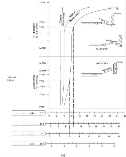
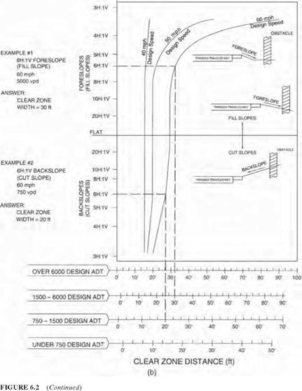
FIGURE 6.2 Clear zone distance curves. (a) SI units; (b) U. S. Customary units. (From Roadside Design Guide, AASHTO, Washington, D. C., 2002 and 2006, with permission) clear zone distance from Fig. 6.2 applies directly. Fixed obstacles such as culvert head – walls should not extend above the embankment in this zone. Nonrecoverable slopes, generally between 1:4 and 1:3, are traversable, but most motorists will reach the bottom of the slope and not be able to stop or return to the roadway easily. Fixed obstacles should not be constructed along such slopes, and a clear runout area at the bottom of the slope is desirable. Critical slopes, generally steeper than 1:3, are those on which a vehicle is likely to overturn. A barrier might be warranted in such cases. Figure 6.3 dis­cusses alternatives that might be considered on critical parallel foreslopes.

Roadside Geometry

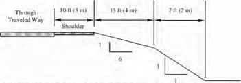
Many highway agencies construct so-called barn roof sections in embankment con­ditions as illustrated in Fig. 6.4. A relatively flat slope is provided adjacent to the roadway, followed by a steeper slope and a clear runout area at the bottom. This is more economical than a continuous flat slope and apparently safer than a continuous steeper slope from the edge of the shoulder. In applying the clear zone concept, side slopes ranging from flat to 1:4 may be averaged to produce a composite clear zone distance. Slopes that change from negative to positive should be treated as channel sections. Changes in slope and toes of slopes should generally be rounded to keep vehicles in contact with the ground and enhance traversability.

EXAMPLE I

Design ADT: 12,000

Design Speed: 70 mph (110 km/h)

Keeonirnended dear-zone distance Гог I V:6II forcslopc: 30 to 34 ft (9 to 10.5 im

Roadside Geometry

Discussion: Since the critical foreslopc is only 23 ft (7 no from the through traveled way. instead of die suggested 30 to 34 ft (9 lo 10.5 in), и should be flattened if practical or considered for shielding. However, if this is an isolated obstacle and the roadway has no significant crash history, it may be appropriate to do little more than delineate the drop-off in lieu of foreslope flattening or shielding

Although a "weighted" average of the foreslopcs may be used, a simple average of the clcar-zone distances for each foreslope is accurate enough if the variable foreslopcs arc approximately the same width II one foreslope is significantly wider, the clcar-zone computation based on that foreslope alone may be used.

EXAMPLE 2

Design ADT: 350

Design Speed: 40 mph (60 km/h)

Recommended dear-zone distance for I V:5II foreslopc: 7 to 10 ft <2 to 3 rni

Roadside Geometry

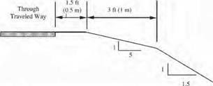
Discussion: The available 4.5 ft 11.5 in) is 2.5 to 5.5 ft (0.5 lo 1.5 ml less than the recommended recovery area. If much of this roadway has a similar cro&s-section and no significant run-off-the-roed crash history, neither foreslopc flattening nor a traffic barrier would be recommended On the oilier hand, even if the I V;5H foreslopc were 10 ft (3 m) w-idc and (he clcar-zone requirement were met. u traffic barrier might be appropriate it (his locution had noticeably less recovery area than the rest of the roadway and the embankment was unusually high.

FIGURE 6.3 Examples of application of clear zone concept to critical parallel foreslopes on (Example 1) high-volume and (Example 2) low-volume highways. (From Roadside Design Guide, AASHTO, Washington, D. C., 2002 and 2006, with permission.)

On backslopes, traversability depends on relative smoothness and the presence of fixed obstacles. If traversable (1:3 slope or flatter) and obstacle free, it may be acceptable. Conversely, a steep rough-sided rock cut (one that will cause excessive vehicle snagging) should be shielded unless it is outside the clear zone.

Transverse slopes may be created by median crossovers, intersecting side roads, or driveways. These generally create a more serious condition than parallel slopes because they can be struck head on by errant vehicles. To minimize the effect, slopes of 1:10

Clear zone distance

Clear runout area required

Through traveled way

Shoulder

Recoverable slope

Nonrecovera

slope

ble

Clear runout area

1:4 or flatter slope (1:6 or flatter desirable)

Slopes between 1:3 and 1:4

1:6 or flatter slope desirable

FIGURE 6.4 Example of “barn roof’ section for parallel foreslope design; recoverable slope is followed by a nonrecoverable slope. (From Roadside Design Guide, AASHTO, Washington, D. C., 2002 and 2006, with permission)

or flatter are desirable where practical. Steeper slopes may be suitable for low-speed facilities. Drainage pipes should be located as far from the roadway as practical. Also, where a vehicle could be led into the culvert inlet or outlet by a drainage channel, consid­eration should be given to special inlet or outlet treatment, as subsequently discussed.

Drainage channels are open flow areas generally paralleling the highway embank­ment within the right-of-way. They serve to collect surface runoff that drains from the highway and convey it to outlets. In addition to providing drainage functions, channels should be proportioned so that they are traversable. The shaded areas in Figs. 6.5 and 6.6 show preferred (traversable) slopes for the sides of channels. Where practical, channel sec­tions outside the shaded areas may be reshaped, converted to a closed system (culvert), or shielded by a barrier. For all channels, roadside hardware (for example, sign supports) should not be located in or near channel bottoms or slopes because vehicles leaving the roadway may be funneled along the channel and impact the obstacle. Breakaway hard­ware may not function properly if impacted by airborne or sideways-sliding vehicles.

APPLICATION OF CLEAR ZONE CONCEPT TO SLOPE AND DRAINAGE DESIGN

The clear roadside concept has a direct and obvious application to the selection of slopes and design of drainage features such as ditches, curbs, culverts, and drop inlets. A traversable, unobstructed roadside zone should extend beyond the edge of the driving lane for an appropriate distance so that the motorist can generally stop or slow the vehicle and return to the roadway safely.

The width of the zone depends on the traffic volume, the design speed, and the road­side slope. Vehicles on high-volume, high-speed routes obviously require more room to recover than those on less congested routes. A suggested guide for determining the width of the clear zone is presented in Fig. 6.2. The clear zone distance (width) is given in terms of the range of design average daily traffic (ADT) or vehicles per day (VPD), the design speed, and the roadside slope. Enter the chart from the left with the slope, intersect the appropriate design speed curve, and project down to the appropriate scale at the bottom to read the suggested width. The width should be used as a guide and may be adjusted for site-specific conditions and practicality. The AASHTO guide gives modifi­cation factors (1.1 to 1.5) that can be applied to increase the clear distance on horizontal curves where accident histories or site investigations show a need. Increased superelevation may be another option, depending on climatic conditions.

Vibratory Rollers

Vibratory rollers should be carefully or, more precisely, consciously used. An addi­tional condition for using vibration is maintaining the appropriate temperature behind the paver to enable the movement of particles during rolling. Applying vibra­tion to a cool SMA mixture is a mistake that leads to the crushing of particles. Vibration is not an option when SMA is being placed in a thin layer (i. e., 20-30 mm), on a stiff base (e. g., concrete slabs or a brick or block pavement), or at too cold of a mixture. Compacting SMA with vibratory steel rollers is generally permitted, but high frequency and low amplitude vibrations are a must (Asphalt Review, December 2004).

Determining the correct type of vibratory roller to use from among the following is important when considering the use of vibration:

• Classic vibratory rollers—used when it is certain that the frequency and amplitude of vibrations do not threaten to crush particles or to squeeze mas­tic out on the layer surface.

• Vibratory rollers with other vibration techniques

• Oscillatory—marked by vibrations within a range of oscillations, com­pacting a shallower depth than classic vibratory rollers but sufficient for a wearing course

• Variable direction of vibration—features the possibility of amplitude direction control.

The use of vibration can be an acceptable method of compacting SMA layers; most producers of rollers currently have solutions to minimize the risk of crushing an SMA skeleton. Obviously using vibration does not apply to the aforementioned situations (thin layer, stiff underlayer, too cold of a mix), a priori limiting the pos­sibility of using vibratory rollers.

Types of Rollers

The following types of rollers can be used for compacting SMA mixtures:

• Static—used as basic equipment for SMA compaction. The heavy (fin­isher) and medium ones operate chiefly in the set. When compacting is executed on thin layers or layers on a stiff underlying, heavy rollers are excluded.

• Vibratory— used for compacting SMA, but only according to some rules mentioned later.

Pneumatic rollers are not typically used due to the risks of mastic sticking to the tires and dragging particles out of the rolled layer and of squeezing mastic out on the surface.

The following rules should be observed when planning for a combination of roll­ers for a work site: [63]

• An extra roller with a side-roll for layer edges should be provided, espe­cially with an increased number of construction joints or connections.

• Rollers fitted with a gritter for finishing SMA surfaces are also indispens­able (see Section 10.7.1).

Building Techniques: Timber Framing for the Rest of Us

T

O THIS POINT, WE HAVE SPOKEN OF CONSIDERATIONS APPROPRIATE for all timber framing projects. But now we have reached a juncture where traditional timber framers go one way and the rest of us take another path. As Yogi Berra said at a college commencement speech, “When you get to that fork in the road take it.” I say, “Let’s start at the bottom and work up.”

Foundation Options

Timber framing can be married quite happily to a variety of foundation methods, which, in general, can be characterized under four separate categories: piers, footings, masonry walls, and slab-on-grade.

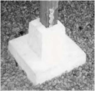
I. Piers. Piers can also be called pillars, columns or posts, and can be made of wood (such as 75-year ground contact six-by-six timbers or railway ties) or of poured concrete. Concrete piers can be in the form of truncated pyramids, such as my friend Steve Sugar did near Hilo, Hawaii (Fig. 4.1 on page 62 and Fig. 4.18 on page 77) or they can be poured within heavy cardboard tubes called Sona tubes. Whether the piers are wood or concrete, they should extend down to below the code-specified frost line where you are building. In northern New York, this is considered to be four feet. It is also a good idea to distribute the load of the post or pier on a large flat stone, say 12 to 16 inches (30.5 to 40.6 centimeters) square. The top of the pillar should be six to twelve inches (15.2 to 30.5 centimeters) clear of grade to protect any wooden post above it, or the sill plate, from damp. Reinforced concrete columns made with Sona tubes can extend three or four feet above grade, if you want to make use of the crawl space under the building.

Подпись:image39While I have nothing against piers made with Sona tubes, my personal view is that the 75-year pressure-treated piers will probably last just as long, are cheaper and easier to install by the inexperienced owner-builder, and if it comes to it, easier to replace.
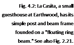
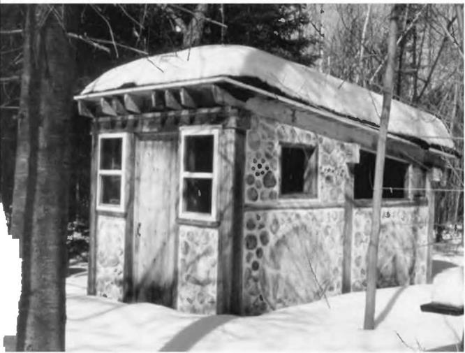
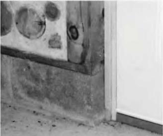
Подпись: Fig. 4.2: La Casita, a small guesthouse at Earthwood, has its simple post and beam frame founded on a "floating ring beam." See also Fig. 2.21.image40Подпись: 3. Masonry walls. Supported by either footings or the slab-on-grade, masonry walls can be poured concrete, block or even stone masonry. These walls can be of the desired height according to the house style (basement, crawl space, etc.) and should be at least as wide as the post and beam frame

ion today, the footings are installed sheltered space is desired below grade, us to:

2. Footings. Generally made of poured concrete, footings might typically be 12 to 16 inches wide and at least 8 inches (203 millimeters) thick.

With small buildings, such as a sauna or our little guest­houses, I “float” the footings on a good pad of percolating material. See slab-on-grade below. I call this foundation a “floating ring beam” and its construction is detailed in both my books Complete Book of Cordwood Masonry House­building and The Sauna (see Bibliography). (Fig. 4.2.)

With most northern construct – below frost line, whether an earth – or simply a “crawl space.” This leads

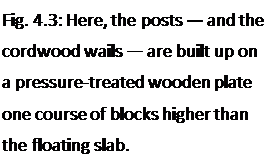
and any intended infilling. For example, if the builder wants a 16-inch-wide cordwood wall, built within a strong post-and – beam frame, the supporting wall (and footings) should also be 16 inches wide. (Fig. 4.3.)

Подпись: Fig. 4.3: Here, the posts — and the cordwood wails — are built up on a pressure-treated wooden plate one course of blocks higher than the floating slab.image414. Slab-on-grade. This is also known as the “floating slab” or the “Alaskan slab.” It works on the sound principal that frost heaving is caused by water freezing and expanding below the building. The two approaches taken to avoid this problem are (1) to go down below maximum frost depth with the footings or (2) to prevent water from collecting under the foundation in the first place. The second approach is the way the slab-on-grade works. The poured concrete slab “floats” on a pad of percolating material such as coarse sand, gravel, or crushed stone. The pad drains any water to a place further down grade. There is no water under the foundation to freeze, so no nasty uplifting expansion (called “heaving”) takes place. Again, see Complete Book of Cordwood Masonry Housebuilding for a thorough discussion. But, be sure to follow local code, too. The slab-on-grade does appear in the new International Building Code, now used in most states.

Incidentally, Frank Lloyd Wright liked both the floating slab and another foundation method, which works on a similar principle, called the rubble trench. By this method, a trench is dug down to just below frost level, and then filled with fairly coarse (potato-sized) stone. Footings are formed and poured on this stone at grade level. The trench is drained to some point down grade, so the method is best suited for a site with sufficient grade differential.

The best discussion of the rubble trench foundation, good enough to build from, appears in the excellent book Foundations and Concrete Work (see Bibliography). Using just the information in that book, Ki Light made his rubble trench foundation. A concrete footing floats on the packed rubble, and his post and beam frame (and his straw bales) are founded on this footing. You’ve already seen Ki’s house in Fig. 1.2.

The present book, though, is about timber framing, not foundation methods. Maybe someday I’ll do a book called Foundations for the Rest of Us, but don’t hold your breath. Almost any good generalized building book (including Foundations and Concrete Work, page 17) will show you how to set up “batter boards” to establish a square foundation. This fine inexpensive book also explains the slab – on-grade and other foundation methods.

Films Create Super Windows

Another way to control the flow of heat through a window is with suspended films. These films come in two varieties: high solar gain and low solar gain.

Because these films (similar to mylar) are so lightweight and thin, as many as three films can be suspended between two glass panes. The additional insulating spaces in­crease the insulating ability of the window, replicating the performance of three-, four-, or five-pane windows without the weight. Serious Windows® uses this approach to cre­ate high-performance windows with both high and low solar-gain properties. The com­pany’s premium fixed window has an insu­lating value of R-11.1 (U-factor 0.09), nearly rivaling many wall insulations. The operable version of the window is R-7.1 (U-factor 0.14). Considering that the average insulat­ing window is the equivalent of R-1 to R-3, Serious Windows live up to their name.

Let the Light Shine In

Solar gain and insulating values aren’t the only ways that windows save energy and keep you comfortable. Windows also control the view and the amount of natural light.

Daylighting, or window-placement strate­gies to maximize natural light, save money by reducing the need for electric lighting. Al­though placement is a design issue, window styles and glass properties affect the amount of light infiltration. The visible transmit­tance (VT) rating on the National Fenestra­tion Rating Council’s label (p. 95) allows you to compare the amount of light that passes through windows, taking into account the light blocked by frames and grilles.

Films Create Super WindowsImpact-Resistant Glass Offers Protection

Although they don’t affect a window’s en­ergy performance, a few options can make you safer.

Tempered glass, for example, can be specified for windows located where some­one could potentially fall into one. Many of these locations are covered by code and include windows within 18 in. of the floor, next to doors, in showers or bath areas, and along decks, patios, and walkways.

If you live in a coastal area—particularly along the Atlantic and Gulf coasts, where building codes demand protection during hurricanes—or in a tornado-prone area, you can specify impact-resistant glass. Using the same technology as car windshields, a plas­tic sheet is laminated between two pieces of glass so that the window maintains its integ­rity after the glass is broken.

Window frames can also be reinforced to withstand impact. Available in three differ­ent strengths (impact zones 2, 3, and 4), the toughest windows in impact zone 4 must withstand strikes from at least two 8-ft.-long 2x4s traveling at 50 ft. per second, followed by 9,000 cycles of negative and positive pressure simulating hurricane-force winds.

Windows That Keep the World at Bay

Manufacturers also offer variations of pebbled, frosted, and wavy glass that add privacy to bathrooms, bedrooms, and other sensitive spaces.

If you live near a busy road, near train tracks, or under a flight path, acoustic win­dows can take the edge off loud or constant noise. Even if they don’t readily advertise the fact, many window companies sell sound-attenuating windows. Residential "quiet" windows are likely to be rated with a sound transmission coefficient (STC). A typi­cal double-pane window has an STC of 25 to
27. Every increase of 10 in the STC cuts the amount of sound transmitted by half. Com­panies such as Milgard®, Atrium®, Marvin, and Serious Windows have windows in the 40 to 47 STC range.

Relationships among failure density function, failure rate, and reliability

According to Eq. (5.3), given the failure density function ft(t) it is a straight­forward task to derive the failure rate h(t). Furthermore, based on Eq. (5.3), the reliability can be computed directly from the failure rate as

Ps(t) = exp


I h(x) dr

0


(5.10)


Подпись: ft (t) = h(t) exp Подпись: I h(x)dr 0 Подпись: (5.11)

Substituting Eq. (5.10) into Eq. (5.3), the failure density function ft(t) can be expressed in terms of the failure rate as

Example 5.3 (after Mays and Tung, 1992) Empirical equations have been developed for the break rates of water mains using data from a specific water distribution system. As an example, Walski and Pelliccia (1982) developed break-rate equations for the water distribution system in Binghamton, New York. These equations are

Pit cast iron: N(t) = 0.02577e00207t

Sandspun cast iron: N(t) = 0.0627e00137t

where N (t) is the break rate (in number of breaks per mile per year), and t is the age of the pipe (in years). The break rates versus the ages of pipes for the preceding two types of cast iron pipes are shown in Fig. 5.9. Derive the expressions for the failure rate, reliability, and failure density function for a 5-mile water main of sandspun cast iron pipe.

Solution The break rate per year (i. e., failure rate or hazard function for the 5-mile water main) for sandspun cast iron pipe can be calculated as

h(t) = 5 miles x N(t) = 0.3185e00137t

The reliability of this 5-mile water main then can be computed using Eq. (5.10) as ps(t) = exp^- J 0.3185e0 0137T d^j = exp[23.25(1 – e00137t)]

Подпись: Pipe Break Rate (Breaks/Mile/Year)

Figure 5.9 Break-rate curves for sandspun cast iron and pit cast iron pipes.


Relationships among failure density function, failure rate, and reliability

ft(t) = 0.3185e00137t x exp[23.25(1 – e00137t)]

The curves for the failure rate, reliability, and failure density function of the 5-mile sandspun cast iron water main are shown in Fig. 5.10.