Openings

Wood Doors

Standard Manufactured Doors

Wood doors, both solid and paneled, are typi­cally treated with biocides and manufactured with toxic glues. Paneled wood doors use less glue than solid veneered doors and will there­fore outgas less. The face veneer used on flush wood doors is luan, a mahogany commonly imported from the Philippines or Thailand, where it is obtained using forestry practices that damage the environment. Interior fire­rated doors and hollow-core doors often contain a particleboard center that will con­tinuously outgas formaldehyde fumes. Stan­dard manufactured doors should be sealed to lock in harmful vapors. We recommended the following specifications when using standard manufactured doors: [12] [13]

• For a painted finish, prime all six sides with one of the primer paints that seals in VOCs, as listed in Division 9.

Custom Wood Doors

Choosing custom doors allows you to select style, type of wood, and finishes. Some custom door manufacturers will work with you to cre­ate a healthier product by using benign glues and less-toxic shop finishes. You can also pur­chase doors unfinished and have the contrac­tor finish them according to your specifica­tions. Although most custom doors are more expensive, some custom door companies have production or builder lines, which are almost cost competitive with manufactured doors. Paulas chemically sensitive clients who wish to have the warmth and beauty of wood with­out the terpene emissions of pine doors will often order doors made of harder, less odor­ous woods such as maple or poplar. For cus­tom doors, specify the following:

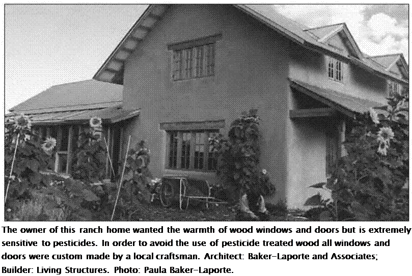
Подпись: The owner of this ranch home wanted the warmth of wood windows and doors but is extremely sensitive to pesticides. In order to avoid the use of pesticide treated wood all windows and doors were custom made by a local craftsman. Architect: Baker-Laporte and Associates; Builder: Living Structures. Photo: Paula Baker-Laporte.

Doors shall be glued with a solvent-free glue such as Elmer’s Carpenter’s Glue, Envirotec Health Guard Adhesive #2101, or Titebond Solvent Free Construction Adhesive.

• Doors shall be finished using the speci­fied low-toxic finish (refer to Division 9 for choices) or with an approved shop – applied finish. Submit a dated sample, MSDS, and product literature for owner’s approval of any proposed shop finishes.

CONCEPTS AND BENEFITS OF ROADSIDE SAFETY

The roadside is defined as that area beyond the traveled way and shoulder. Thus, road­side safety is concerned with treatments that minimize the likelihood of serious injuries when a vehicle runs off the roadway.

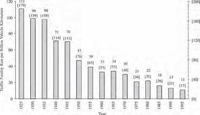
Roadside safety design has received particular emphasis since the 1960s. The increased awareness of its importance and the development of improved safety concepts and devices have contributed significantly to improved safety. As shown in Fig. 6.1, the traffic fatality rate expressed in terms of driven distance has declined to one-third of that in the mid-1960s. Many factors have contributed to the declining rate, including safer vehicles (occupant restraints, door beams, crash energy management, etc.) and improved roadways (intersection geometry, superelevation, grade separation, etc.). However, road­side improvements have played a key role in reducing fatalities.

Cost-effective roadside safety concepts and features must be incorporated in both new construction and in rehabilitation projects.

CONCEPTS AND BENEFITS OF ROADSIDE SAFETY

FIGURE 6.1 Traffic fatality rate continues to decline. (From Roadside Design Guide, AASHTO, Washington, D. C., 2002 and 2006, with permission)

Roadside safety must be addressed because a significant number of vehicles inevitably leave the roadway. There are a variety of reasons for this, such as:

• Driver fatigue or inattention

• Excessive speed

• Driving under the influence of alcohol or drugs

• Collision avoidance

• Roadway condition (ice, snow, rain)

• Vehicle component failure

• Poor visibility

To reduce the severity of accidents involving these errant vehicles, the roadside should have relatively flat slopes and be free of fixed objects. What is known as the forgiving roadside concept has generally become an integral part of highway design criteria. Obstacles most often responsible for roadside fatalities include

• Trees and shrubs

• Utility poles

• Culverts and ditches

• Curbs and walls

• Sign and luminaire supports

• Bridge piers and abutments

Design options often employed for addressing a roadside obstacle include

• Removing the obstacle

• Redesigning the obstacle so it can be safely traversed

• Relocating the obstacle

• Using breakaway devices

• Shielding the obstacle with a barrier or crash cushion

• Delineating the obstacle

As with virtually all highway construction, funds for safety improvements are limited, and thus, emphasis must be given to improvements that are cost-effective and offer the greatest opportunities for safety enhancement. Some features such as breakaway supports and bridge railings are routinely included on the basis of a subjective analysis of obvious benefits. In other cases, where alternatives exist, benefit-cost and value engineering studies should be used to aid in rational decisions. Benefits include expected reduction in accident costs, including the cost of personal injuries and property damage, based on the expected reduction in number and severity of accidents associated with the improvement. Costs include direct construction cost and maintenance. The study must be based on a specific project life so that benefits and costs can be annualized. This involves the application of discount rates and life-cycle costs as discussed in Chap. 10. The computer program Roadside Safety Analysis Program (RSAP) is available to aid in the selection process. Contact the Transportation Research Board, NCHRP, 2101 Constitution Ave. NW, Washington, D. C. 20418.

The Roman aqueducts in Gaul

The growth and prosperity of the period of peace between 97 and 180 AD directly ben­efits the Roman provinces. All Gallo-Roman cities of importance benefit from one or several aqueducts during this period, under the reigns of Nerva, Trajan, Hadrian, Antonius, and Marcus Aurelius, then until 235 AD under Severus. Aix-en-Provence and Lyon have four aqueducts; later on we will examine those of Lyon in detail. At Vienne, where the sources are very near,[232] we know of eleven aqueducts; at Poitiers (Lemonum) and Perigueux (Vesone), three. Some of these aqueducts are quite simple in design, with a very regular slope, as at Perigueux and Rodez. Others have quite a variable slope, most often steeper upstream than downstream, and with quite a variety of hydraulic works: tunnels, bridges, drops, siphons. The average slope itself can be quite variable from one aqueduct to another; it is usually between 0.2 and 1.6 m/km. One notable singularity is the Craponne aqueduct at Lyon, whose average slope is 16 m/km.

The dimensions and discharges of the aqueducts are also quite variable. The aque­ducts of largest cross-sectional area are at Vienne and Nimes. At Lyon and Nimes, the lengths rival those of the aqueducts of Rome itself (50 to 75 km). What is striking from the outset is, as shown in table 6.3, the diversity of configurations. Yet the dates of con­struction, when known, are most often in the 1st and 2nd centuries AD, the period of prosperity, Roman peace, and the concomitant economic climate favorable for develop­ment of the provinces. Samples of the broad panorama of Roman techniques of this period, adapted to local conditions, can be found in Gaul. We too rarely know the his­tory of these aqueducts, histories that are sometimes quite dynamic[233] as conditions change. The needs for water can increase over time, or the discharge available from the sources can decrease. Calcareous water can clog the conduits with deposits.

At Sens (Agedincum), the Fauconderie spring (on the left bank of the Vanne) is ini­tially the sole water source for the aqueduct. But when the spring dries up, four other springs are tapped successively until the flow is restored to, or slightly exceeds, the ini­tial supply. The aqueduct is increased in length from 6.1 km to 14.2 km, so as to reuse both the canal between the former Fauconderie spring and Sens, and the bridge on which the aqueduct crosses the valley of the Vanne.

At Saintes (Mediolanum), after some fifty years the capacity of the aqueduct is reduced due to the increase in roughness caused by calcium deposits. Therefore the aqueduct is completely rebuilt, being replaced by one of larger cross-sectional area but flatter slope, capturing water from new springs and delivering it to the city at a higher elevation. This reconstruction, like that of Sens, was based on re-use of large art works – the two bridges called the Arcs (27 arches, 298 m long) and the Hautmont (62 arches, 400 m long) as well as the tunnel of Neufs Puits. On these bridges, the canal is simply raised. But along underground segments, major construction efforts are devoted to mod­ification of the cross section. However, the water from new sources is even more cal­careous than the original. According to the estimates of Marcel Bailhache, the discharge, which had been increased from 4,000 to 22,600 m3/day by the reconstruction, subse­quently decreases to a value of only about 8,000 m3/day.

At Toulouse (Tolosa), the capturing of supplementary sources increases the dis­charge of the Ardenne aqueduct. But the resulting water depth (0.66 m) ends up exceed­ing the depth of the 40-cm canal lining, thus causing serious degradation of the canal walls.

Water quality is a strong determinant of the longevity of the aqueducts. If the water is calcareous, lime encrustation can reduce the flow area and increase the roughness to the point of reducing the discharge capacity by a factor of two in a few decades. Without maintenance, the canal can become completely blocked. On the other hand, if the water is not calcareous, the canals can have a very long lifetime. The aqueduct of Sens, for example, will be used up until the middle ages.

The most important works are those of Lyon and Nimes.

Table 6.3 A collection of synthesized data on the principal known Gallo-Roman aqueducts, listed in decreasing order of length.[234]

Note: The useful depth indicates the height of impermeable lining opus signinum The discharges in parentheses are those that we have been able to calculate when there is a constant slope on a sufficiently long reach, assum­ing a roughness height of 3 mm for the canal walls.

Name

Length

(km)

Avg Slope

(m/km)

Est. Max. Flow

(m3/day)

Total

Depth

(m)

Useful

Depth

(m)

Width

(m)

Remarks

Lyon:

86

1.5

15,000

1.7

1.33

0.6

4 siphons;

Gier Aq.

11 tunnels

Lyon:

70

5.3

10,000

1.4

0.94

0.55

1 siphon;

Brevenne Aq.

1.7

0.54

0.75

8 drops

continued from page 145

Name

Length

(km)

Avg Slope

(m/km)

Est. Max. Flow

(m3/day)

Total

Depth

(m)

Useful

Depth

(m)

Width

(m)

Remarks

Arles:

55

8,000

1.3

0.65

Eygalliere Aq.

Nimes

49.7

0.25

(40,000)

1.85

1.2

1.2

1

Passes over Pont du Gard

Reims

44

0.5

22,000

1.4

0.9

0.7

1

3 tunnels (800 m; 1,850 m;

(34,000)

and 900 m); regular slope

Frejus

40

12?

1.07

0.67

0.7

1

Several bridges

Beziers:

37

2,500 to

1.05

0.8

0.42

1,300 m tunnel

Gabian Aq.

5,000

Cahors

33

1.4

3,800

1.6

0.5

0.2

1

Trapezoidal section (largest

to

0.8

below the top)

Rodez

30

1.6

38,000

1.4

0.7

0.55

Terminal siphon;

(32,000)

regular slope

Lyon:

26

3.2

6,000

0.9

0.6

0.45

Two siphons

Mont-d’Or Aq.

Carhaix

27

0.3

4,000

?

0.8

0.6

800 m tunnel

Lyon:

27

16.8

8,000

?

0.6

0.5

1 double siphon; vortex

Craponne Aq.

drop shafts

Poitiers:

25

0.123

6,700

1.21

0.75

0.75

Likely dates from 2nd cen-

de Fleury Aq.

0.46

0.9

)

tury

1

Aix:

24

8

1.1

0.69

Traconnade Aq.

Metz

22

1

22,000

1.6

0.92

1.1

Bridge over the Moselle,

1300 m long and 30 m high

Narbonne:

22

1.4

8,500

1.5

1.2

0.59

Only upstream 11 km

Cabezac Aq.

known

Paris:

15.7

0.56

2,400

0.5

0.45

0.37

Water depth does not

Arcueil Aq.

exceed 0.28 m (deposits)

Sens

6.1

1

39,000

1.56

0.9

0.56

Dates from the 2nd centu-

14.2

ry;

later lengthened

Vaison-la-Romaine

12

1

0.6

Siphon under the Ouveze

Besan$on: Arcier Aq.

10.3

2

(69,000)

1.5

0.8

0.8

Toulouse: Lardenne

9.5

1

19,000

1.15

0.4

0.65

Saintes: 1st canal

5

0.85

4,000

0.5

0.5

0.2

1

Two siphons

reconstructed canal

7.5

0.87

22,600

0.7

0.45

(2 km)

Lisieux

7

0.7

0.5

Sant-Bertrand-de-

2.7

1

13,600

1.4

0.5

0.7

1

5-meter cascade

Comminges

(18,000)

Perigueux:

2

0.66

6,200

0.66

0.66

0.37

Water depth = 0.33 m

Grand-Font Aq.

(4,200)

(deposits); regular slope

The aqueducts of the city of Rome at the end of the 1st century AD

The accession of Nero to supreme power marked the beginning of a somber period for Rome.[228] Civil war followed his assassination in 68 AD, then came the too-short reigns of Vespasianus and Titus. After a promising start, Domitian becomes morbidly suspi­cious, and sheds the blood of those near to him and his collaborators only to end up being assassinated himself in 96 AD. Then Nerva, an old senator, is chosen as the new emper­or in a climate of restoration of the old Roman virtues. We have noted earlier that the Romans placed high symbolic value on water; among the early preoccupations of the new emperor is the restoration of water distribution in the city. For this he calls on a for­mer collaborator and experienced administrator: Sextus Julius Frontinus, 61 years old, former governor of Britain, i. e. Great Britain, and former preconsul of Asia. In 97 Nerva names Frontinus as curator aquarum, translated as “high commissioner for water” of the city of Rome. Frontinus is a methodical man who takes his responsibili­ties seriously. At the beginning of his service, Frontinus prepares a written description of the aqueducts of the city for his own information and then continues with written descriptions of his observations, measurements, and actions during his tenure. This trea­tise has come down to us, and we have already cited several extracts. We can learn much about both the characteristics and the history of these aqueducts from Frontinus’ writings (Table 6.2).

The principal aqueducts at the time of Frontinus came from the region of the Sabine mountains; the four largest ones, Anio Vetus, Marcia, Claudia and Anio Novus, came from the valley of the Anio, upstream of Tivoli (the Roman Tibur) (see Figure 6.8). Where this river flows out onto the plain of Rome, at Tivoli, the aqueducts leave the val­ley of the Anio and trace a large arc in the direction of the Alban mountains, thus main­taining their elevation as they near the city of Rome. On the Frascati heights, they are rejoined by the Tepula and Julia aqueducts, and complete their trajectory to the city on arches. At their entrance into Rome, the Anio Novus flows above the Claudia, on the same arches (Figure 6.9). Similarly, the canal of the Julia is above those of the Tepula and the Marcia, all three superposed on the same arches. These five aqueducts flow on a slope of about 1.3 m/km in their final reaches.[229]

What surely motivated Nerva to put things in order was that the amount of legally distributed water was far less what it was expected to be, as dictated by the written impe­rial records. The new curator aquaraum therefore took it upon himself to make dis­charge measurements in the aqueducts, both at their origins and at their points of arrival in the city. To his surprise, he found that now the measured discharges were well above those specified in the official registers. There could only be one conclusion: there had been fraud, greater fraud than had originally been suspected!

Here we must pause to note the significance of discharge for the Romans. Not hav­ing understood or recognized the physical concept of water velocity, the Romans found it sufficient to measure the flow cross-section at spots where the water velocity was

Table 6.2 The nine aqueducts of Rome in the days of Frontinus (about 100 AD)[230] Two other aqueducts, the Trajana and the Alexandrina, are constructed later. The indicated discharges are estimated from the equivalence: 1 quinariae = 40.6 m3 per day. The total discharge (all but Alsietina) is 977,00 m3/day.

Name

Construction

Date

Length (km) and % under­ground

Avg

Slope

(m/km)

Discharge (i. e. Area) (quinariae)

Estimated

Discharge

(m3/day)

Origin and quality of water

Appia

312 BC

16.5

(95%)

0.6

1,825

73,000

Spring in the Anio valley. Excellent

Anio Vetus

272 BC

64

(99%)

3.6

4,398

175,900

Anio River.

Somewhat

muddy

Marcia

144 BC

91

(88%)

2.7

4,690

187,600

Captured from springs Excellent

Tepula

125 BC

18

(46%)

5

445

17,800

Captured from ground­water.

Warm water

Julia

33 BC

22

(54%)

12.4

1,206

48,200

Springs.

Excellent

Virgo

19 BC

21

(92%)

0.2

2,504

100,200

Springs.

Excellent

Alsietina

2 AD

33

(99%)

6

392

15,700

Lake

Alsietinus nonpotable (used for water games)

Claudia

47 AD

69

(78%)

3.8

4,607

184,300

Springs.

Excellent

Anio Novus

52 AD

87

(84%)

3.8

4,738

189,500

Anio River. Muddy

judged to be neither excessive nor too weak. The Roman unit of discharge, the quinar – ia, is actually just a measure of area (4.2 cm2), whereas everyone knows today that vol­umetric discharge is the product of the velocity and the cross-sectional area of the canal. What Frontinus really measured is the depth of water in well-defined locations in the canal, from which he deduces the area and therefore calculates his estimate of discharge in quinariae. The discharges shown in table 6.2 are based on a fixed relation between quinariae and real discharges. We will discuss this further at the end of this chapter, regarding the hydraulic knowledge of the Romans. As imprecise as it was, this system nevertheless enabled Frontinus to detect the important deficits and differences described above:

“I do not doubt that many will be surprised that according to our gaugings, the quantity of water was found to be much greater than that given in the imperial records. The reason for this is to be found in the blunders of those who carelessly computed each of these waters at the outset. Moreover, I am prevented from believing that it was from fear of droughts in the summer that they deviated so far from the truth, for the reason that I myself made my gaugings in the month of July, and found the above-recorded supply of each one remaining constant throughout the entire remainder of the summer. But whatever the reason may be, it has any rate been discovered that 10,000 quinariae were intercepted, while the amounts granted by the sovereign are limited to the quantities set down in the records.

“Another variance consists in this, that one measure is used at the intake, another, consid­erably smaller, at the settling-reservoir, and the smallest at the point of distribution. The cause of this is the dishonesty of the water-men, whom we have detected diverting water from the public conduits for private use. But a large number of landed proprietors also, past whose fields the aqueducts run, tap the conduits; whence it comes that the public water­courses are actually brought to a standstill by private citizens, just to water their gar­dens.”[231]

This observation is rather severe. Numerous wildcat taps provide a clandestine water supply to those living adjacent to the aqueducts, and support a parallel, unofficial water market. Nearly half of the water delivered to Rome by the aqueducts escapes the official accounting. But what also upsets Frontinus is that water from the different aque­ducts is senselessly mixed together without taking into account the quality of the differ­ent sources. The last aqueduct built under Claudius, (predecessor of Nero), the Anio Novus, serves to complete the aqueduct system, and its additional supply was useful in obscuring the pilfering:

“The two Anios (aqueducts) are less limpid, for they are drawn from a river, and are often muddy even in good weather, because the Anio, although flowing from a lake whose waters are very pure, is nevertheless made turbid by carrying away portions of its loose crumbling banks, before it enters the conduits (….)

“One of the Anio (aqueducts), namely Old Anio (Anio Vetus), running at a lower level than most of the others, keeps this pollution to itself. But New Anio (Anio Novus) contaminated all the others, because, coming from a higher altitude and flowing very abundantly, it helps to make up the shortage of the others; but by the unskillfulness of the water-men, who divert­ed into the other conduits oftener than there was any need of an augmented supply, it spoiled also the waters of those aqueducts that had a plentiful supply, especially Claudia, which, after flowing in its own conduit for many milles, finally at Rome, as a result of its mixture with Anio, lost till recently its own qualities. And so far was New Anio from being an advan­tage to the waters it supplemented that many of these were then called upon improperly through the heedlessness of those who allotted the waters. We have found even Marcia, so

charming in its brilliancy and coldness, serving baths, fullers, and even purposes too vile to „75

mention.

The aqueducts of the city of Rome at the end of the 1st century AD

Figure 6.8 Layout of the aqueducts of Rome. This map also shows the Trajana and the Alexandrina, built after the magistracy of Frontinus. See Figure 6.36 for the imperial ports. Adjacent: elevations of the aqueducts at their points of arrival in Rome. The Aqua Marcia is shown on a Roman coin (author’s collection).

Frontinus devotes the three years of his mission to reducing these clandestine diver­sions, and improving the distribution system, both quantitatively and qualitatively. He restores respect for the quality of consumable water, and moves the intake of the Anio Novus further upstream to capture clearer water. He also improves the reliability of sup­ply to the public fountains, supplying each with two outlets so as to assure continuous supply when work is being done on one of the aqueducts.

25 Ibid., 90-91.

The aqueducts of the city of Rome at the end of the 1st century AD

Подпись: Figure 6.10 Evolution of discharge delivered into Rome by the aqueducts, compared with the evolution of the city's population.26 The vertical error bars reflect uncertainty in present-day estimates of the city's population.

Figure 6.9 The Agua Claudia and the Aqua Anio Novus on the same arches, at the Porta Maggiore of Rome. The aqueduct was integrated into the new city wall under the emperor Aurelius, in the 4th century AD (photo by the author).

26 The discharges are those of table 6.2, after Frontinus. The demographic data are taken from Christol andNauny (1997).

Whatever may have been these problems in managing the system, they did not reflect any fragility in the supply of water to the city. Figure 6.10 shows how the increase in discharge delivered to Rome accompanies the demographic growth. With nearly a cubic meter of water per person per day, a Roman inhabitant had nearly a hundred times more water than his or her counterpart in Paris of the 19th century!

Later, two additional aqueducts are constructed, but they are less well known to us since they came after the writings of Frontinus. They are the Trajana, constructed around 110 AD under the grand Emperor Trajan, successor of Nerva; and the Alexandrina, built under Alexander Severus in 226 AD. From the 2nd century AD, Rome falls into a kind of recession, and its population probably stabilizes. This second century is the century of the provinces, insofar as expansion is concerned. The construc­tion of grand aqueducts begins again in these provinces, in particular in Gaul, Spain, and Africa.

Miscellaneous Wall Framing Layout

Each building has unique characteristics that require special attention. Hold-downs, shear walls, blocking, backing, special stud heights, and posts are some of the more common miscellaneous framing items. The framing language for these framing items is not well-defined because the operations frequently change and the same ones are not always used. The Miscellaneous Layout

Language Chart on the next page gives you an idea of how these framing tasks can be communicated.

Hold-Downs

Hold-downs are probably the most difficult to mark correctly. They vary from location to location and require different studs or posts for connecting.

Vv

Top plate tacked to bottom plate hanging over edge of concrete for layout

■2 * 10 BV 361/2 X

■2 * 10 BV 361/2 X

Offset backer

Crayon marked

There are also different types of hold-downs, and each manufacturer has its own identification system. There are, however, four basic styles of hold-downs that you need to show in your wall layout.

1. Basic hold-down: bolts, nails, or screws to the hold-down post or studs. This type is typically attached to an anchor bolt in the foundation or bolted to an all-thread rod that is connected to a hold-down in the wall below. (See “Hold­Downs with Floor Between" illustration.)

2. Hold-down already embedded in the concrete, which needs only to be attached to the wall. (See “Hold-Down in Concrete" illustration.)

3. Strap used to connect the top of one wall to the bottom of the wall above. (See “Strap Wall to Wall" illustration.)

4. Hold-down that is continuous between all floors from the foundation to the top floor. (See “Hold-Down, Continuous" illustration.)

The difficulty in laying out for hold-downs is knowing what to write on the plates so that the requirement will be easily understood. The best thing to do is to explain to all framers at the beginning of each job what symbols you are using to indicate hold-downs. Use the same language when possible at different jobs. The most common symbol for hold-downs is HD, followed by the number representing the size of the hold-down—for example, HD2 or HD5.

When you are laying out for hold-downs, it’s important to get the layout in the right location. Since the purpose of a hold-down is to connect the building to the foundation, the hold-downs must

line up with the anchor bolt in the foundation below them. Hold-downs are typically found at the end of shear walls. Engineers sometimes position hold-downs attached to posts at the ends of walls or within a specific distance from the ends of walls. If that information is not specified, keep the hold-down as close to the end of the wall as possible. If the hold-down anchor bolt is already in the concrete, then you can only position it in two locations—one on either side of the hold-down anchor bolt. (See “Hold-Down Either Direction" illustration.)

If the epoxy system is specified for installing the anchor bolts later, you have more options. A good rule of thumb is to keep the hold-down within one

foot of the end of the wall. However, the shorter the wall, the closer the hold-down should be to the ends of the wall.

When laying out for a hold-down, you want the studs or post to be in the correct position in relation to the anchor bolt or hold-down in the wall.

A good way to make sure the distance from the studs to the anchor bolt is correct is to use one of your hold-downs to mark the pattern and location of the studs or post. (See “Hold-Down as Pattern" photo.) If you do not have a hold-down available for this purpose, you can use the manufacturer’s hardware catalog to find the distance from the anchor bolt to the studs.

When you are laying out for the hold-downs on an upper floor, it is helpful to mark the location of the hole to be drilled in the plate and the floor. You have to locate the hole anyway to lay out the studs. By marking its location, you are saving someone else from having to locate it again. It is easiest to go ahead and drill the holes through the floor then, before the walls are built. These holes can be oversized to make alignment easier.

Shear Walls

Shear walls have unique characteristics, but the most common information a framer needs to know about them is the type of sheathing, the edge nail spacing, and the nail spacing for nailing of the bottom plate. This information can usually be found in a shear wall schedule in the plans. The sheathing used is typically either plywood or OSB, commonly identified as "W," or gypsum, identified as "G." The edge nailing is designated as a number after the W

or G, and the floor nailing as a number before the W or G. An example could be "6W4," meaning that the bottom plate is nailed at 6” on center, the sheathing is plywood, and the edge nailing is 4” on center. The language for shear walls can be written on the plates with the other language, but it is best to also write it on the top of the bottom plate. That way, when you get around to nailing the wall down, the nailing pattern will still be visible.

EXAMPLES FROM THE DEMONSTRATION PROJECTS

Many of the demonstration projects used trusses and several used the simplified trim details described above. However, several projects also used vaulted ceiling rafter framing to provide more open space in relatively small homes. In some houses the vaulted ceilings provided lofts and expandable space.

Lincoln, Nebraska

Karl Witt used vaulted ceilings with clerestory windows in the living area of his homes. This provided a degree of passive solar heating and natural lighting.

Everett, Washington

Vaulted ceilings with clerestory windows and open soffit overhangs were used in Everett.

Mesa County, Colorado

Instead of the more typical 1/2-inch plywood roof sheathing, Roger Ladd used 3/8-inch plywood with metal plyclips.

An excellent opportunity exists to reduce construction costs through innovative plumbing. But plumbing is also one of the more difficult areas to get innovations adopted. In spite of the fact that present model plumbing codes are updated periodi­cally, the process is lengthy and uncertain, so none of the model codes reflect current state-of-the-art.

In addition, comprehensive model plumbing codes cover all types of buildings and are overly complex for dealing with relatively simple re­quirements of single family dwellings.

The four major model plumbing codes are the BOCA Basic Plumbing Code. the SBCC Standard Plumbing Code, the NAPHCC National Standard Plumbing Code, and the ІАМРО/ ICBO Uniform Plumbing Code.

Many local jurisdictions use one of the model codes with their own modi­fications. In almost all cases, local modifications are more restrictive in material and design than the parent model code.

Confronted with these facts, the NAHB National Research Center has compiled a state-of-the-art manual for residen­tial plumbing. This effort, sponsored by NAHB and HUD, resulted in Residential Plumbing Guidelines which contains all requirements to assure a safe, functional, durable, and cost – effective residential plumbing system. NAHB submitted proposed code changes to the Council of American Building Officials (CABO) in 1984, and the proposed changes were adopted in January, 1986.

Substantial changes were made in some areas of the code. Following is a synopsis of the more relevant changes that affect the installed cost of plumbing.

The load on the drain, waste, and venting (DWV) system is determined by drainage fixture unit (d. f.u.) values.

This is a measure of the probable discharge into the drainage system by various types of plumbing fixtures and is used to size DWV piping systems.

The newly adopted d. f.u. values are, in every case, less than those in the old CABO code. The old values are basically the same as those used in the other major model codes.

The new CABO code includes d. f.u. values for plumbing fixture groupings. These values are less than the sum of individual fixture units, which recognizes the fact that d. f.u. values are not additive when the probability of simultaneous use is very, very low.

The new CABO code allows 75 foot spacing of cleanouts versus 50 foot spacing in the old code. This is consistent with standard available snake lengths.

The new CABO code allows smaller size traps and trap arms for some fixtures. Below-grade drain pipe mini mums were reduced from 2 to 11/2 inches in diameter because of power driven cleanout equipment capabilties.

In practice, large diameter drain pipe is often perceived to be desirable. However, with the lower discharge rates of modern residential fixtures manufactured to water conserving standards, large diameter drains have very low flow rates which promote deposition of solids.

Smaller diameter pipe with higher flow rates actually provides improved transport characteristics. This is a classical case where bigger is not necessarily better and where tradi­tional thought is outdated.

The new CABO code allows an increase in maximum trap arm lengths. This provides a degree of architectural flexibility such as the location of kitchen sinks under windows.

The purpose of the venting system is to maintain atmospheric pressure within the DWV system and to provide venting of gasses by circulating air throughout the system. At low flow rates, characteristic of residential construction, vent pipes need only be of small diameter. In addition, vents need not penetrate the roof. Rather, vents can extend through an exterior wall or roof overhang and terminate downward.

According to the new CABO code, "A common vent may be used for two waste fixtures connecting at different levels in the stack but within the same branch interval, provided the vertical drain is one pipe diameter larger than the upper fixture drain, but in no case smaller than the lower fixture drain. The vertical piping between fixture connections serves as a wet vent for the lower fixture." (Section P-2207.7.1, One and Two Family Dwelling Code).

The CABO code also states, "Stack venting, with certain preconditions relating to drainage loads and vent­ings, fitting types and sizes, and placement of connections, shall be permitted as a system that allows fixtures and fixture group to be independently connected to a soil or waste stack without individual fixture venting." (Section P-2207.8, One and Two Family Dwelling Code).

EXAMPLES FROM THE DEMONSTRATION PROJECTS

The significance of these paragraphs cannot be overlooked inasmuch as the total cost of plumbing DWV in an average home can be reduced substan­tially. When combined with other DWV innovative practices, total costs have been reduced by as much as $400, depending on which code was used as the comparison.

Because of this (and the fact that the techniques have been proven for many years to be safe and reliable), it will be well worth while for builders to push for adoption of the plumbing section of the CABO code.

Water Service As with DWV piping, water service
and Distribution requirements in the CABO code have

been changed significantly toward cost reduction and efficiency. Health standards have been maintained in all cases.

In all major model codes acceptable water service pipe materials include copper, galvanized steel, PVC or CPVC plastic, polyethylene plastic, and polybutylene plastic. Some local codes are more restrictive, especially in use of plastic pipe.

The lack of competition in materials often tends to keep the cost of the only acceptable materials high. If for no other reason, a variety of acceptable materials is desirable.

Section P-2405.3 in the new CABO code, individual fixture stops are considered optional for single-family housing. Experience has shown that individual fixture stops often deterio­rate between time of installation and time of their eventual use to the degree that they may require service or replacement. They also create potential sources of leaks. This is a case where possible convenience is offset by more probable inconvenience. ‘ In any case, convenience items should not be codified.

Water supply fixture unit (w. s.f. u.) values have been changed in the new CABO code and are consistent with established values in fitting standards. The new w. s.f. u. values for both hot and cold water provides for selection of pipe sizes based on reasonable estimates of peak demands. Measure­ments made m numerous field and laboratory tests have confirmed these values.

Minimum size offixture water supply pipes for all fixtures, except dish­washers and lavatories, is 3/8 inch in the new CABO code. For dishwashers and lavatories, minimum size is 1/4 inch. Fixture group main minimum sizes are either 3/8 inch or 1/2 inch, depending on number and size of fixture branch pipes connected.

The CABO code also recognizes the different flow rates of different pipe materials and the w. s.f. u. values vary accordingly. Therefore, supply pipe often can be reduced in size depending on the number and type of fixtures.

The significance of the new CABO One and Two Family Dwelling Code cannot be overemphasized. Studies have shown a total cost reduction in supply piping of as much as 24 percent even when the same piping material is used.

For more information on the innova­tions discussed herein, write the Council of American Building Officials, 5203 Leesburg Pike, Suite 708, Falls Church, VA 22041.

Подпись: Other Cost Saving TechniquesThere are methods to reduce plumbing costs regardless of code restrictions. Some may require negotiating with the plumbing subcontractor to get full benefit, others may require market evaluation to determine consumer acceptability.

Cluster the plumbing. This cost-saving design principle is to arrange plumbing groupings back-to-back in a common wall and to shorten distances of other plumbing runs as much as possible. In multiple-story buildings, fixtures should be located over each other to minimize DWV and supply piping. Savings can amount to as much as 10 percent. Plumbing subcontractors often bid on a "per fixture" basis so the value of clustered plumbing may not be passed on without negotiation.

White plumbing fixtures are less expensive than colored fixtures. A savings of $40 to $75 per bath can be realized. From a consumer standpoint, any accent or decorating color can be used with white fixtures.

Consider fiberglass bathing modules. They often are less expensive than other bathtub/shower materials.

Wall hung lavatories can reduce costs although vanities have become standard. Wall hung units may be a marketing problem, but they should be considered, especially in powder rooms and/or second bathrooms.

Size water heaters according to intended use. Smaller homes intended for small families do not need large water heaters. Thirty-gallon gas or 30- to 40-gallon electric water heaters are generally adequate. Also, water heaters with a five-year warranty cost about $20 less than units with a ten – year warranty. This reflects an lV additional five-year insurance policy, not the basic construction of the water heater.

Consider polybutylene supply piping. This material is flexible and, there­fore, requires only about 1/3 the number of fittings as rigid pipe materials. It normally costs much less to install and has some ad­vantages in flow characteristics.

Field studies have shown cost savings of between 30 and 50 percent.
Sloped Roofing Materials

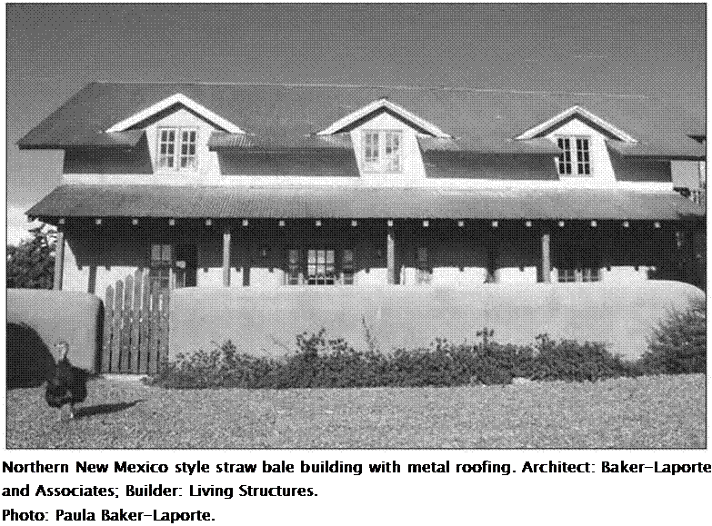
Asphalt-based rolled roofing and shingles will outgas when heated by the sun and should be avoided. Clay tile, concrete tile, metal, and slate are all inert, long-lasting slope roof solutions. Wood shingles can be a good roofing material where fire danger is low and humidity is mod­erate and if rot resistant woods such as cedar are used. Zinc or copper strip applied at the ridge will wash wood shingles with preserva­tives every time it rains. Availability of roofing materials varies from region to region.

Roofing Underlayments

In many cases, roofers will want to install an asphalt-based felt paper over the roof sheath­ing. Several non-asphaltic-based underlay – ments are now available to choose from:

• RoofShield: High permeability three – layer spun bond polypropylene underlay – ment

• RooftopGuard: Five-layer polypropylene/ polyethylene underlayment

• StrongSeal Roofing Underlayment: Con­tains no asphalt; both nail-down and self­adhering membranes

• Titanium UDL: Non-asphaltic, coated synthetic roofing underlayment for sloped roofs

Подпись: Northern New Mexico style straw bale building with metal roofing. Architect: Baker-Laporte and Associates; Builder: Living Structures. Photo: Paula Baker-Laporte.

Membrane Roofing

Membranes for flat roofing can be problem­atic. These roofs are in fact more accurately described as having a very low slope, usu­ally Va inch per foot or less. Tile, shingles, and most metal applications that depend on rapid water runoff will not hold up under standing water conditions and are not suitable for low – slope roofs.

Built-up tar and gravel roofing is the most common and least expensive material avail­able for flat roof applications, but we do not recommend it. A tar and gravel roof will emit volatile organic compounds from asphalt, benzene, polycarbon aromatics, toluene, and xylene. It will continually outgas when heated by the sun. Some of these vapors will inevi­tably find their way into the living space and degrade air quality Eventually the roof will
outgas to the point where it does not adversely affect indoor air quality, but soon thereafter it will require replacement. The average tar and gravel roof is guaranteed for only two to five years and may require replacement in less than 10 years. Since most people are not in a position to move out for several weeks when their roof is repaired or replaced, they will be exposed to high levels of toxic fumes. Chemi­cally sensitive individuals often have difficulty tolerating a tar and gravel roof that is less than one to two years old.

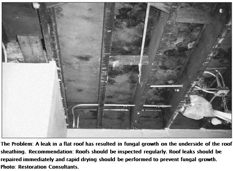
Toxicity is not the only health concern to consider when choosing a product. Many per­sistent mold infestations begin with an unde­tected roof leak. No type of roofing installation is foolproof, but the use of high quality roofing materials and skilled installers will reduce the risk of leakage.

Подпись: The Problem: A leak in a flat roof has resulted in fungal growth on the underside of the roof sheathing. Recommendation: Roofs should be inspected regularly. Roof leaks should be repaired immediately and rapid drying should be performed to prevent fungal growth. Photo: Restoration Consultants.

Although other solutions are typically more expensive than tar and gravel, you must carefully weigh both lifecycle and health costs when making a roofing choice. Single-ply membranes such as Brai Roof contain asphalt and will also outgas to a certain extent during application when heat is applied to fuse the membrane. Once installed, they are fairly sta­ble. These roofs also carry a longer warranty. Brai Roof can be applied in two ways. It can be mechanically fastened, with seams heat welded together. This is the less odorous method and the one we recommend. It can also be glued down with a layer of hot-mopped tar and seams can be sealed with hot tar. We do not recom­mend this technique. Certain single-ply mem­branes can be repaired by welding patches onto the existing roof, thereby extending the roof s life for many years. There are also roll-on roof­

ing products that do not require roofing con­tractors for application or repair.

It is especially important with roofing ma­terials that the manufacturer s instructions for installation and the warranty criteria be care­fully followed. Here are some more benign alternatives to tar and gravel roofing for flat – roof applications:

• AFM Safecoat Dynoflex: Low-toxic roof coating to replace tar and gravel that can be walked on and remains flexible

• Brai Roof: An asphaltic-based single-ply membrane (specify mechanical fastening and torch-down application)

• Mirrorseal: A single-ply, fluid-applied roofing system

• Resource Conservation Technologies, Inc.: An acrylic polymer paint or roll-on system that uses titanium dioxide with
propylene glycol and contains no toxic dis­persants or tints

• Stevens EP: A heat weldable, scrim rein­forced, single-ply roofing membrane made of ethylene propylene

Joint Sealants

Many solvent-based caulking compounds are formulated with hazardous solvents such as acetone, methyl ethyl acetone, toluene, and xylene. They are toxic to handle and may out – gas for extended periods of time. The follow­ing are suggested options for exterior use:

• loo percent silicone aquarium-grade caulk of any brand. Aquarium-grade does not contain any additives that will harm fish and therefore will be safer for humans as well. Be sure to read content labels because some are labeled ‘pure silicone’ but con­tain other ingredients.

• AFM Safecoat Caulking Compound: Water-based elastic emulsion.

• DAP: loo percent Silicone Sealant or Sili­cone Plus.

• GE Silicone II: Silicone sealant formu­lated for different types of application; some may contain biocides.

• Lithoseal Building Caulk: Urethane mod­ified polymer, inert once cured.

• Phenoseal Surpass Caulk and Sealant, Valve Seal, Vinyl Adhesive Caulk: Line of water-based sealants and caulks.

• Weatherall UV Guard Premium Caulk­ing: A professional strength acrylic-based sealant designed for use in a wide variety of construction applications.

Further Reading

Lafavore, Michael. Radon: The Invisible Threat. Rodale Press, 1987.

Lstiburek, Joseph. Builders Guides. Available

through The Energy & Environmental Building Association, 10740 Lyndale Avenue South, Suite 10W, Bloomington, MN 55420,952-881-1098, eeba. org. A series of climate-based field guides with explanations, details, and techniques to effectively implement energy – and resource – efficient residential construction

Lstiburek, Joseph and John Carmody. Moisture Con­trol Handbook: Principles and Practices for Resi­dential and Small Commercial Buildings. Van Nostrand Reinhold, 1993.

US Environmental Protection Agency. A Citizens Guide to Radon. 2nd ed., US Government Print­ing Office, ЕРА 402-K-92-001, May 1992.

US Environmental Protection Agency. Consum­ers Guide to Radon Reduction. US Government Printing Office, ЕРА 402-K-92-003, May 1992.

US Environmental Protection Agency. Indoor Ra­don and Radon Decay Reduction Measurement Device Protocols. US Government Printing Of­fice, EPA 402-R-92-004, July 1992.

US Environmental Protection Agency. Model Stan­dards and Techniques for Control of Radon in New Residential Buildings. US Government Printing Office, EPA 402-R-94-009, March 1994.

US Environmental Protection Agency. Radon Con­tractor Proficiency (RCP) Program. US Gov­ernment Printing Office, ЕРА 402-B-94-002, September 1994.

Evolution of aqueduct techniques

The Cretan, Greek, and later the Hellenistic aqueducts primarily use terra-cotta pipes. The Romans, following the Etruscan heritage, build their aqueducts as masonry canals, usual­ly rectangular in section, and covered over by a vault or stone slabs. The aqueducts are fit­ted with openings at regular intervals (from tens to hundreds of meters apart) to facilitate inspection and maintenance. We have seen earlier that the Aqua Appia, the first Roman aqueduct built in 312 BC, is nearly entirely underground. This practice is surely inherited from the Etruscan techniques, but also has a military dimension, since Italy is still far from being pacified at this time – this is only eleven years after the death of Alexander.

The Romans stay with this concept throughout the long period of aqueduct construc­tion in the Empire, i. e. from the 4th century BC to the 3rd century AD. A canal (specus) is, depending on the local topography, sometimes laid on the surface or on a supporting wall, or sometimes buried underground, occasionally passing through true tunnels, and, when necessary, supported on arched structures. The longitudinal profile of an aqueduct is driven by two constraints: first to maintain sufficient slope to convey the water, as regular as possible to avoid local break points; and second to deliver water at a high enough elevation to supply the city’s water tower (castellum) and thus enable distribu­tion of water to the highest areas of the city. Thus the arch structures that one often sees near the cities are needed to keep the canal at a sufficiently high elevation. And it is of course these arch structures, still visible today in numerous locations of the Roman Empire, that one commonly associates with the Roman aqueducts. However one should not forget that these structures represent only a small fraction of the total length of an aqueduct. The slopes of the canals are quite variable, as we will see in examples pre­sented further on, but most often are of the order of one meter per kilometer. Occasionally, where there is a need to drop to a lower elevation, there are local chutes comprising short sections of steep slope, or even true cascades.

Table 6.1 Characteristics of several known Roman aqueducts (after Hodge, 1995; Leveau, 1979; and other sources).

Location

City

Length

Average slope

Estimated

(km)

(m/km)

discharge

(m3/day)

Italy

Rome

11 aqueducts; see Table 6.2

1,127,220

Bologna

20

1.00

35,000

France

Lyon (Lugdunum)

4 aqueducts; see Table 6.3

Metz (Divodurum)

22

0.56

22,000

Nimes (Nemausus)[217] [218]

50

0.25

40,000

Arles (Arelate)

48

0.625

8,000

Strasbourg (Argentorate)

20

3.13

2,160

Germany

Treves (Augusta Treverorum)

13

0.6

25,450

Cologne (Colonia Agrippina)

95.4

3.89

27,000

Mayence (Mogontiacum)

28.6

Switzerland

Geneva

11

0.55

8,640

Neuchatel (Aventicum)

8

4.4

2,880

Spain

Segovia (Segovia)

15

16.4

1,728

Tarragona (Tarraco)

35

Toledo (Toletum)

50

England

Dorchester (Durnovaria)

15

5,200

Africa

Cherchell (Caesarea)11

40

2

38,000

Carthage (Cartago)[219] [220]

90.4 (Zaghouan) 118 (Djoukar)

2.9

17,280

Syria

1 3

Apamea-on-Orontes

150

1.3

Turkey

Pergamon (Pergamum)[221]

50

0.3

20,000

Let’s once again listen to Vitruvius:

“Water is conducted in three ways, either in streams by means of channels built to convey it, in leaden pipes or in earthen (terra cotta) tubes (that is, according to the Greek process cited earlier), according to the following rules. If in channels, the structure must be as solid as pos­sible, and the bed of the channel must have a fall of not less than half a foot to a length of one hundred.[222] These channels are arched over at top, that the sun may strike on the water as lit­tle as possible.

“(….) If hills intervene between the city walls and the spring head, tunnels under ground must be made preserving the fall above assigned; if the ground cut through be sandstone or stone, the channel may be cut therein, but if the soil be earth or gravel, side walls must be built, and an arch turned over, and through this the water may be conducted.”[223]

A masonry canal is not inherently watertight. Therefore it is necessary to plaster the useful (or “wetted”) walls of the canal, both to minimize leakage and to protect the masonry walls themselves from infiltration damage. The Roman plaster (opus signinum) is of very high quality. It is a mortar of crushed tile solidified with thick lime, also con­taining crushed brick and pottery shards, and sometimes other additives.[224]

The most imposing and important structures are those necessary to carry the aque­ducts across valleys. These are the famous bridge-aqueducts such as the Pont du Gard near Nimes (47.8 m high), or the bridges of Segovia and Tarragona in Spain or, similar­ly, the bridge of Chabet Ilelouine on the Cherchell aqueduct in Algeria, all three some thirty meters high. There are also the inverted siphons echoing the technology of the Hellenistic world. These expensive siphons are reserved for valleys more than 50 m deep, a depth beyond which the cost of a bridge becomes prohibitive. Further on we describe the siphons of Lyon, the largest ones in the Roman world, but it is first useful to provide a glimpse of this Roman technology.

Roman inverted siphons begin with a head tank, receiving water from the aqueduct’s canal, then distributing the water into one or more parallel lead pipes leading out of the basin. These pipes descend to the bottom of the valley and cross it on a bridge-siphon, and then come back up on the other side to an exit, or escape, basin. This exit basin then delivers water into the continuation of the aqueduct (Figure 6.7). Vitruvius emphasizes the need to provide a rather long and rectilinear length of siphon at the low point of the valley (the “venter”):

“(…) when it arrives at the bottom, let it be carried level by means of a low substruction as great a distance as possible; this is the part called the venter, by the Greeks coelia. When it arrives at the opposite acclivity, the water therein being but slightly swelled on account of the length of the venter, it may be directed upwards.

“If the venter were not made use of in valleys, nor the level substruction, but instead of that the aqueduct were brought to an elbow, the water would burst and destroy the joints of the

pipes. Over the venter long stand pipes (collivaria) should be placed, by means of which, the

violence of the air may escape. Thus, those who have to conduct water through leaden pipes,

may by these rules, excellently regulate its descent, its circuit, the venter, and the compres – 1 8

sion of the air.”

One can appreciate the value of a rectilinear “venter” (usually implemented as a bridge-siphon) in reducing the hydrodynamic force that would be concentrated on a small-radius elbow at the valley floor. But the reasons given by Vitruvius (i. e. to avoid the excessive “swelling” of the water) somewhat miss the mark. There has been consid­erable questioning of what is meant by the colliviaria. Some have interpreted them as purges to eliminate air. According to Henning Fahlbusch,[225] [226] [227] they are towers supporting an elevated intermediate reservoir, acting like a modern surge tank to purge air from the siphon’s “venter”. Such towers are useful when, in an inverted siphon, there are elbows or high points favorable to the formation of air pockets. The Tourillon de Craponne, on one of the aqueducts of Lyon that we describe further on, could serve as an example. Possible remains of others can be found at Aspendos, in the south of Anatolia.

Evolution of aqueduct techniques

Figure 6.7 The types of works found on Roman aqueducts: bridge, arches, tunnel, inverted siphon

Table 6.1 presents a synthesis of data for a number of known aqueducts in the Roman Empire. It shows that the aqueducts could reach quite significant lengths, often up to 50 or 100 km. But the length of an aqueduct is not, by itself, a good indicator of its grandeur. The construction of bridges, arcades, tunnels, etc. in effect reduces the length of an aqueduct, limiting the numerous detours that would be necessary if the structure had to follow the local topography along the ground surface. Certain aqueducts are actu­ally shortened during renovation, thanks to the construction of such projects. This is notably the case for the Aqua Marcia, one of the aqueducts of Rome:

“But now, whenever a conduit has succumbed to old age, it is the practice to carry it in cer­tain parts on substructures or on arches, in order to save length, abandoning the subterranean 20

loops in the valleys.”

Sequential Extraction Methods

Selective extraction can be considered as an “operational speciation” as it corre­sponds to the quantification of elements bound to specific phases of the soil, rather

LEACHING TESTS FOR GRANULAR MATERIALS

pH Domain 4-5

pH 5-6

Material Dictated

Complexation

Low L/S

TCLP

Swiss TVA

DIN 38414 S4

MBLP (Synth)

MBLP

EPtox

NFX-31-210

(California WET

EN 12457-3 (at

test)

L/S =2 & 10)

Availability test

O-norm S2072

Wisconsin SLT

(NEN 7341) California WET

EN 12457

Ontario LEP

Canada EE MCC-3C

Quebec QRsQ

ASTM D 3987

Soil HAc

Soil – NaNO3 Soil – CaCl2

Table 7.1 Examples of leaching (and speciation) tests from around the world (adapted from van der Sloot et al. (1997) and from Hill (2004))

Single Batch Leaching Tests (equilibrium based)

Multiple Batch and Percolation Tests (mostly based on local equilibrium)

Serial Batch (low L/S) Serial Batch L/S>10 UHHamburg NF-X 31-210

WRU WRU

EN 12457-1 ASTM D4793-88

(at L/S = 2) NEN 7349 (NVN 2508)

MEP method 1320 Sweden ENA

MWEP

EN 12457-2 & -4 (at L/S = 10)

Static Methods Speciation Methods

Pacific Northwest Lab. MCC-1 Pacific Northwest Lab. MCC-2 Compacted granular tank leaching test (Rutgers/ECN)

LEACHING TESTS FOR MONOLITHIC MATERIALS

ANSI/ANS 16.1

Tank leaching test NEN 7345 (a static test, non-agitated)

Spray test (impregnated wood)

Swedish MULP

EN 1744-3 (static test, agitated)

The codes in this table refer to various standards or standards originating organisations. Readers who are uncertain of their meaning are referred to the original sources. L/S = Liquid:solid ratio.

than to an exhaustive analysis of the chemical species in the material. (Tessier et al., 1979; Quevauviller et al., 1993). Selective extraction procedures of pollutants from soils can be simple or can be organised according to a sequential or parallel extraction pattern.

Simple extraction procedures are not much used to determine the operational speciation of metals in materials but are used in soil sciences in order to quantify their potential availability for plants.

Sequential and parallel extractions follow the same principle: to submit the ma­terial to a series of reactants in order to identify associations between the different components of the material and the pollutant. Such procedures are more informa­tive than simple extractions as they allow study of the geo-chemical partitioning of pollutants.

Parallel extractions involve different test portions of the same sample subjected to different reactants, while sequential extractions aim to submit the same sam­ple to a well-ordered series of reactants with increasing aggressiveness. Different parallel extraction procedures have been proposed by Seme (1975), Forstner & Patchineelam (1976) and Cazenave (1994) (as cited in Lara-Cazenave, 1994) and also different sequential extraction procedures e. g. Gupta & Chen (1972), Engler et al. (1974), Tessier et al. (1979), Salomons & Fortsner (1980), Meguellati (1982), Welte et al. (1983) and Morrison & Revitt (1987) (as cited in Flores-Rodrigues, 1992).

Associations that are usually studied in most selective extraction protocols are (Colandini, 1997):

• the exchangeable fraction: pollutants are removed from clayey minerals and amorphous materials by simple ion exchange (neutral salts such as MgCl2, BaCl2 or CH3CO2NH4 are used);

• the fraction associated to carbonates: metals (co-)precipitated with natural car­bonates are easily dissolved by a pH decrease (a weak acid as CH3COOH is enough to dissolve calcite and dolomite);

• the fraction associated to metal oxides: metals associated to oxides of Fe, Al and Mn are extracted by means of a reducing agent (as hydroxylamine hydrochlo­ride – NH2OH. HCl);

• the organic fraction: under oxidizing conditions (H2O2 is used under acidic con­ditions) organic compounds are mineralized and metals are released; and

• the residual fraction: includes elements that are naturally present into the matrix of minerals.

In principle the different mineral phases can be quite precisely isolated thanks to the use of a series of extractions. However, the chemical attack on a phase does not always lead to a complete dissolution of pollutants contained in that phase, and for sequential extractions this can result in the dissolution of metals contained in other phases of the sample. Moreover, pollutants released by mineralization of a phase can be reincorporated by remaining phases. Thus, during sequential extraction measuring errors can accrue through the different steps. Despite these drawbacks, there remains a key benefit: that this method requires less material than parallel extraction.

As a conclusion of a European research programme (Ure et al., 1993) a 4-step harmonized sequential extraction method of heavy metals from soils and sediments was proposed by the Bureau Communautaire de Reference: [19]

• extract metals of the oxidizable fraction (using H2O2 8.8 M; CH3COONH4 1M; pH 2); and

• extract the residual fraction (using HF + HCl 15.5 M).

POCKET DOORS, BYPASS DOORS & BIFOLD DOORS

POCKET DOORS, BYPASS DOORS & BIFOLD DOORSPOCKET DOORS, BYPASS DOORS & BIFOLD DOORS

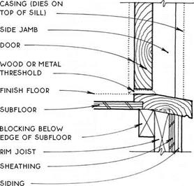
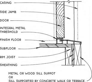
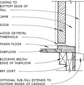
TRADITIONAL WOOD SILL WITH DRIP SLOPES AT 10° & REQUIRES THAT TOP OF RIM JOIST & COMMON JOISTS BE SHAVED OFF FOR INSTALLATION. SILL EXTENDS TO OUTSIDE EDGES OF DOOR CASINGS.

EXTRUDED SILLS OF ALUMINUM OR POLYCARBONATE ARE THE MOST COMMON FOR ALL MODERN DOORS. THE THRESHOLD IS INTEGRAL. THE SILL MUST BE SUPPORTED AT OuTER Edge. ExTRuDED SILLS May ALSO Be USED IN Slab-On-Grade cONSTRUcTION.

POCKET DOORS, BYPASS DOORS & BIFOLD DOORSПодпись: SOLE PLATEПодпись: PLASTIc OR METAL PAN FITS IN DOOR ROUGH OPENING (USE NO FASTENERS THROUGH PAN).POCKET DOORS, BYPASS DOORS & BIFOLD DOORS

FLATTENED WOOD SILL SLOPES AT 7° & IS INSTALLED ON TOP OF JOIST SYSTEM. OUTSIDE EDGE IS FLUSH WITH JAMB (SHOWN) OR CASING.

NOTES

ADJUST PROFILE OF SILLS FOR OUTSWINGING DOORS.

WEATHERSTRIP BOTTOM OF DOOR.

WOOD SILLS ARE NOT COMPATIBLE WITH SLAB SUBFLOORS.

EXTRUDED SILLS

INTERIOR Flange cOORDINATES wiTH SILL & FINISH FLOOR.

BOTTOM FLANGE OF PAN LAPS SHEATHING & DOOR wRAP.

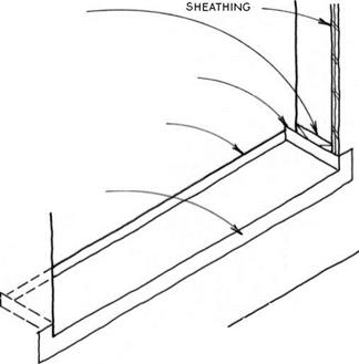
NOTE MOISTURE BARRIER (NOT SHOwN FOR cLARITY) cONTINUOUS AROUND SIDES OF ROUGH OPENING & LAPS SIDES OF SILL PAN, SEE 89.

AT DOOR LOcATIONS ExPOSED TO THE wEATHER, A GALvANIzED METAL DOOR-SILL PAN FIT INTO THE DOOR ROUGH OPENING wILL PROTECT THE STRUCTURE OF A wOODEN FLOOR SYSTEM BELOw.

Подпись: DOOR-SILL PAN^ WOOD SILLS

POCKET DOORS, BYPASS DOORS & BIFOLD DOORS

POCKET DOORS, BYPASS DOORS & BIFOLD DOORSPOCKET DOORS, BYPASS DOORS & BIFOLD DOORS

Подпись: (A GARAGE DOORS
POCKET DOORS, BYPASS DOORS & BIFOLD DOORS

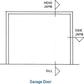
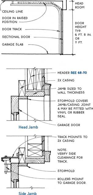
Residential garage doors have evolved from swinging and sliding types to almost exclusively the overhead variety. They are manufactured primarily with a solid – wood frame and plywood or particleboard panels. Paneled metal, fiberglass, and vinyl doors are avail­able in some regions. There are two operating types, sectional and one-piece, both which can be manual or fitted with automatic openers.

Sectional doors— Sectional doors are by far the more common (see 101B). They are hinged horizontally— usually in four sections—and roll up overhead. The advantages are that a sectional door is totally protected by the structure when in the open position, and that it closes to the inside face of the jamb, making the design of the jamb opening somewhat flexible.

One-piece doors – One-piece doors pivot up. The door fits within the jamb and extends to the outside of the building when in the open position. This exposes the open door to the weather. The advantage of this type of door over a sectional door is the greater design flexibility afforded by the single-piece door. Hardware for this type of door is not usually available locally.

POCKET DOORS, BYPASS DOORS & BIFOLD DOORS
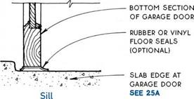
Flashing is essential to keeping water away from the structure and the interior of a building. It is used wher­ever there is a horizontal or sloped penetration of the outer building skin or a juncture of dissimilar materials that is likely to be exposed to the weather. Flashing provides a permanent barrier to the water and directs it to the outer surface of the building, where gravity carries the water down to the ground. Of course, the best protection against water penetration of walls is an adequate eave, but wind-driven rain may make this strategy occasionally unreliable.

Wall flashing, which provides the first line of defense against water, should be taken very seriously, especially because walls, unlike roofs, are not intended to be replaced regularly. Wall flashing is likely to be in place for the life of the building.

Two physical properties affect the flow of water on vertical surfaces. The first property, gravity, can be used to advantage in directing water down the wall of a building. The other property, surface tension, cre­ates capillary action that results in water migrating in all directions along cracks in and between materials. In

many cases, the negative effects of surface tension can be avoided by the proper use of a drip.

A drip is a thin edge or undercut at the bottom of a material placed far enough away from the building surface so that a drop of water forming on it will not touch the wall but will drop away (see 103A). Drips may be made of flashing or may be cut into the building material itself.

In the case of vertical joints, a sealant may be required to counter the effects of surface tension. Except for vertical joints that cannot be flashed effec­tively, a well-designed flashing (see 103-105) is always preferable to a bead of sealant.

Common flashing materials include galvanized steel, baked enamel steel, aluminum, copper, stainless steel, and lead. Because flashing materials may be affected in different ways by different climates, air pollutants, and building materials, the selection of appropriate mate­rials is specific to each job. It is also important to isolate different metals when flashing to prevent corrosive interaction (galvanic action) between them. Consult with local sheet-metal shops for appropriate materials for specific applications.