WARRANTS FOR ROADSIDE BARRIERS

Longitudinal roadside barriers are used to shield motorists from natural or human – made obstacles located along either side of the traveled way, and sometimes to protect pedestrians and bicyclists. Median barriers and barrier end treatments are discussed separately in Arts. 6.9 and 6.12.

Barriers must contain and redirect vehicles. Because of the complicated dynamic behavior involved, the most effective way to ensure performance of new designs is through full-scale crash testing. Standard crash tests are presented in NCHRP Report 350, “Recommended Procedures for the Safety Performance Evaluation of Highway Features.” To match barrier performance to service needs, a series of six test levels are recommended to evaluate occupant risk, structural integrity, and postimpact vehicle behavior. Various vehicle masses, velocities, and impact angles are included. To view acceptance letters for longitudinal barriers under NCHRP 350, visit the FHWA web site, http://safety. fhwa. dot. gov/fourthlevel/hardware/longbarriers. htm.

NCHRP Report 350 establishes six test levels (TLs) for longitudinal barriers to evaluate risk, structural integrity of the barrier, and vehicle postimpact behavior. A range of vehicle weights (masses), speeds, and impact angles are addressed. The AASHTO Roadside Design Guide provides the following description:

TL-1, TL-2, and TL-3 require successful tests of an 820 kg (1800 lb) car impacting a barrier at an angle of 20 degrees and a 2000 kg (4400 lb) pickup truck impacting a barrier at an angle of 25 degrees, at speeds of 50 km/h, 70 km/h and 100 km/h (30 mph, 45 mph, and 60 mph), respectively. TL-4 adds an 8000 kg (17,600 lb) single-unit truck at an impact angle of 15 degrees and 80 km/h (50 mph) to the TL-3 matrix. TL-5 substitutes a 36,000 kg (80,000 lb) tractor-trailer (van) for the single-unit truck and TL-6 substitutes a 36,000 kg (80,000 lb) tractor-trailer (tanker). (p. 5-1)

Barriers typically go through an experimental phase in which a barrier that has passed crash test evaluation is subjected to an in-service evaluation, and an opera­tional phase in which a barrier that has proven acceptable in the in-service evaluation is used while its performance is further monitored. Barriers are also considered opera­tional if they are used for extended periods and demonstrate satisfactory performance in construction, maintenance, and accident experience.

The criteria by which the need for a safety treatment or improvement can be determined are termed warrants. Barrier warrants are based on the premise that traffic barriers should be installed only where they reduce the probability or frequency of potential accidents. Warrants may be based on a subjective analysis of roadside conditions or a benefit-cost study (life-cycle cost analysis). The latter can be used to rationally analyze factors such as design velocity and traffic volume in relation to barrier needs and associated costs and accident costs.. Three options may be evaluated:

• Remove or reduce the area of concern so that it does not require shielding.

• Install an appropriate barrier.

• Leave the area unshielded.

The last of these options would usually be cost-effective only where the accident probability is low.

The main uses of roadside barriers are to shield either embankments or obstacles, as discussed below. Barriers may also be used to protect pedestrians, school yards, or bicyclists. There are no firm criteria for these applications, and each must be evaluated on its own merits.

CONNECTING TO FIXTURES

Electrical connections to light or fan fixtures are simple: ground wire pigtail to green screw (if any), hot pigtail to black lead wire or gold screw, and neutral pigtail to white lead wire or silver screw. If fixture lead lines are stranded, cut them a little longer than solid-copper pigtails so that both will seat correctly when they’re spliced with wire nuts. Push-in Wago Wall-Nuts are a good alternative (see "A New Kind of Nut,” on p. 248). Physical connections, such as mounting fixtures

WIRING A RECEPTACLE

image504

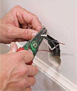
After finish walls are installed and painted, attach the wires to the devices. Start by stripping the wire ends.

image505

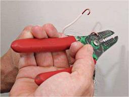
Some wire strippers have a small hole near the handle. Insert a stripped wire, flip your wrist 180 degrees and— voila!—a perfect loop and faster than needle-nose pliers.

to outlet boxes and attaching outlet boxes to framing, are covered on pp. 260-261.

Wiring fixtures quickly gets complicated when three – or four-way switches control fixtures, as you’ll see shortly. If the fixture is a combo—say, a light and fan—each function is usually controlled by a separate switch. Running three-wire cable (for example, 14/3 with ground) to the fixture enables you to run a separate hot wire to both the fan and the light.

INSTALLING SWITCHES

О First, turn off the power. Switches interrupt the flow of current through hot wires only. Neutral wires and ground wires are always con­tinuous, never interrupted. Whether a switch controls a receptacle, fixture, or appliance, hot wires only are attached to switching terminals.

Single-pole switch. A single-pole switch is sim­ple to install. Splice the ground and neutral wire groups as described for receptacles, in the pre­ceding sections. Attach the grounding pigtail to a green grounding screw on the switch, if any. Splice the neutral wires together with a wire nut; they need no pigtail because they don’t attach to switches. Finally, strip h in. of insulation from the ends of the hot wires and attach them to the switch terminals—either by screws or back wiring. It’s customary to install a single-pole switch with the manufacturer’s name at the top, so that the switch toggle will be up when a light is on and down when off.

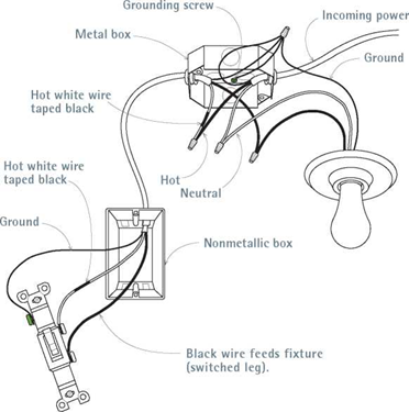
Bending a cardinal rule. When an outlet box is closer to the power source than to the switch box, a single cable may run to the switch, as shown in "Switch at End of Cable,” on the facing page. Splice the ground and neutral wires from the source; then attach a neutral pigtail to a fixture lead wire. However, the hot wire from the source should not attach to a fixture lead—instead, the


WIRING A SWITCH


image507

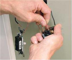
To back-wire switches, first attach the ground wire to the green screw. Then strip the insulated wire ends, using the stripping gauge on the back of the switch. Insert the wires into the terminal holes.


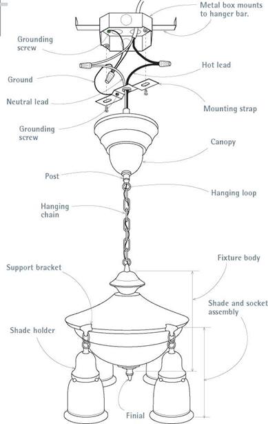
Wiring a Victorian Light Fixture


image508

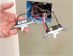
Two types of switches. Left:a single-pole switch; right: a three-way switch. The three-way switch shown has two traveler wires—one red and one white painted black to indicate a hot wire.


image509

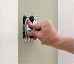
After wiring the switch, push it into the box to prepack its wires and seat it in the position you want. Caution: Don’t be tempted to use box screws to pull the devices in or you’ll end up with crooked devices and stripped screw threads.


image506

Connecting the incoming wires to fixture leads is standard: hot to hot, neutral to neutral, and splice ground wires. All metal parts should be grounded; if you’re attaching to a metal box, the grounding pigtail to the mounting strap is optional. Note: Fixture bodies and mounting devices vary considerably.

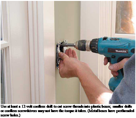
Подпись: Use at least a 12-volt cordless drill to cut screw threads into plastic boxes; smaller drills or cordless screwdrivers may not have the torque it takes. (Metal boxes have prethreaded screw holes.)

incoming hot wire is spliced to a cable wire run­ning to the switch.

Here, for convenience, we break the rule of using the white wire only as a neutral wire and instead use black tape on each end of the white wire, to show that it is used as a hot wire. At the switch, attach the black wire and the white wire (taped black) to the switch terminals. This allows you to use inexpensive two-wire cable as a switch loop. Thus painting or taping the white wire black is a breach of the rule in letter only, because both wires are technically hot. We have not mixed actual hot and neutral wires.

More complex switches. Switch wiring gets complex when three – and four-way switches require three – or four-wire cable (plus grounds). If you get confused, redraw each configuration, identifying hot wires with an H, neutral wires with an N, and so on. At each splice remind your­self: Neutral wires and ground wires are continu­ous; switches interrupt hot wires.

If switches or light fixtures have green grounding screws, run a pigtail to them from the

Подпись: Switch at End of Cable

image511,image512

Light Fixture at End of Cable

Подпись: Switch-wiring at its simplest: Incoming and outgoing hot wires attach to the terminals of a single-pole switch. Neutrals and ground are continuous.Attach the incoming neutral to a fixture lead; run the hot to a switch at the end of the cable. Use the white wire of a two-wire cable as one of the hot wires attaching to the switch—but tape both ends of the white wire black to show that it’s hot.

Подпись: I Two Switches, Two Fixturesimage513Подпись: This is a typical setup for switches by exterior doors. For example, one single-pole switch controls an exterior light fixture, while the second switch controls an interior fixture.

Three-Way Switch

image514

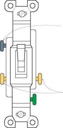
Common (COM) terminal

Traveler wires attach to gold screws.

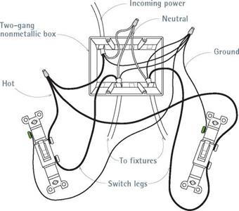
Three-way switches control power from two locations. Each switch has two gold screws and a black screw (common terminal). The hot wire from the source attaches to the common terminal of the first switch. Traveler wires between the switches attach to the gold screws. Finally, a wire runs from the common terminal of the second switch to the hot lead of the fixture.

ground-wire splice (many older fixtures may not have grounding screws). However, if you’re using metal boxes, they must always be grounded: In this case, loop a pigtail from the ground-wire splice to a green screw attached to the metal box.

Conduit and Flexible Metal Cable

The NEC requires that conductors be protected by conduit or flexible metal cable where conduc­tors are exposed, where conductors run through metal studs (and could get nicked), where high moisture could corrode conductors, and so on. Flexible metal cable has factory-installed conduc­tors (wires). But you need to pull conductors through conduit.

FLEXIBLE METAL CABLE

Flexible metal cable is commonly used in remod­eling, and it satisfies most code requirements. In addition to its use in branch circuits, MC is

Repair rate and its relationship with repair density and repair probability

The repair rate r (t), similar to the failure rate, is the conditional probability that the system is repaired per unit time given that the system failed at time zero and is still not repaired at time t. The quantity r (t) dt is the probability that the system is repaired during the time interval (t, t + dt] given that the system fails at time t. Similar to Eq. (5.3), the relationship among repair density function, repair rate, and repair probability is

r (t 1=t—GW,5-22’

Given a repair rate r (t), the repair density function and the maintainability can be determined, respectively, as

г c t -|

Подпись: I r(T) dr 0 Подпись:

Repair rate and its relationship with repair density and repair probability Подпись: (5.24)

gt(t) = r (t) X exp

5.1.2 Mean time to repair, mean time between failures, and mean time between repairs

The mean time to repair (MTTR) is the expected value of time to repair of a failed system, which can be calculated by

n TO n TO

MTTR = rgt (r) dr = [1 — Gt (r)] d r (5.25)

00

The MTTR measures the elapsed time required to perform the maintenance op­eration and is used to estimate the downtime of a system. The MTTR values for some components in a water distribution system are listed in the last columns of Tables 5.2 and 5.3. It is also a commonly used measure for the maintainability of a system.

The MTTF is a proper measure of the mean life span of a nonrepairable system. However, for a repairable system, the MTTF is no longer appropriate for representing the mean life span of the system. A more representative indicator for the fail-repair cycle is the mean time between failures (MTBF), which is the sum of MTTF and MTTR, that is,

MTBF = MTTF + MTTR (5.26)

The mean time between repairs (MTBR) is the expected value of the time be­tween two consecutive repairs, and it is equal to MTBF. The MTBF for some typ­ical components in a water distribution system are listed in Tables 5.2 and 5.3.

Example 5.6 Consider a pump having a failure density function of ft(t) = 0.0008exp(-0.0008t) fort > 0

and a repair density function of

gt(t) = 0.02 exp(-0.02t) for t > 0

in which t is in hours. Determine the MTBF for the pump.

Solution To compute the MTBF, the MTTF and MTTR of the pump should be calcu­lated separately. Since the time to failure and time to repair are exponential random variables, the MTTF and MTTR, respectively, are

MTTF = 1/0.0008 = 1250 hours

MTTR = 1/0.02 = 50 hours

Therefore, MTBF = MTTF + MTTR = 1250 + 50 = 1300 hours.

Shingling across a valley

When a porch roof intersects the main roof at a right angle, a valley is formed. Shingles can be laid across a vallev in different wavs.

4 4

A woven valley is formed by weaving shingles across the valley, alternately overlapping from the main roof onto the porch roof, then vice versa. When properly done, a woven valley is watertight. Let each course of shingles overlap the valley by at least 12 in. and keep nails 8 in. or more from the centerline of the vallev.

4

An alternative to a woven valley is a closed, or cut, valley. To create a cut valley, let all shingle courses from the main roof lap across the porch valley by at least 12 in. Don’t alter­nate back and forth from the main roof to the porch roof. After the shingles are laid on the main roof, lay the shingles on the porch roof

Shingling across a valley

Install step flashing at roof-wall intersections

Use metal step flashing to waterproof the intersection where a roof butts into a wall. Usually made from aluminum or copper, metal step flashing is bent to form a series

of elongated, L-shaped pieces that ere lapped over each other in successive shingle courses as well as upward along the wall. The step flashing we used on this house is 10 in. by 6 in., and each leg is 3 in. wide.

The illustration at left shows how step flashing is installed on each course of shingles that runs into a wall. (Its also used where shingles meet a chimney or a skylight curb.) Each time a regular shingle is laid covvn, a step shingle is placed under it—on the part of the regular shingle that will be covered. Lap step shingles by about 2 in. One nail above the tar strip should be enough to hold each step shingle in place. As each successive course of shingles is nailed in place, a portion of the step shingle on the roof is covered. Later, when the wall is covered with siding or stucco, the vertical leg will be covered as well.

Supports for Utility Poles

Utility supports represent a serious hazard that accounts for about 10 percent of all fixed-object fatal crashes. Elimination, relocation, and burying the lines are preferred options. Increased spacings or multiple use may reduce the number of poles. A breakaway device has been tested and may be considered for vulnerable locations. A breakaway device for utility pole guy wires has also been developed. As with other obstacles, shielding is also an option.

6.3.1 Trees

Collisions of single vehicles with trees account for nearly 25 percent of fixed-object fatal crashes and result in about 3000 deaths each year. Most of these are along county and township roads, which tend to have narrow recovery zones. Certainly, trees should not be planted in the clear zone for new construction, and mowing should discourage growth of seedlings. For existing situations, the hazard should be evaluated. Generally, a single tree with an expected mature size over 4 in (100 mm) is considered a fixed object. For small trees close together, calculate an equivalent diameter based on the combined cross-section area. Large trees should be removed where possible. Warning signs and roadway delineators can be used to indicate where extra caution is advised. Pavement markings and shoulder rumble strips can be helpful. Roadside barriers should generally be used only where the severity of striking the tree is greater than that of striking the barrier.

Repair density and repair probability

Like the time to failure, the random time to repair (TTR) has the repair density function gt (t) describing the random characteristics of the time required to re­pair a failed system when the failure occurs at time zero. The repair probability Gt(t) is the probability that the failed system can be restored within a given time period (0, t]:

Gt(t) = P(TTR < t) = f gt(t) dr (5.19)

90

The repair probability Gt (t) is also called the maintainability function (Knezevic, 1993), which is one of the measures for maintainability (Kapur, 1988b). Main­tainability is a design characteristic to achieve fast, easy maintenance at the lowest life-cycle cost. In addition to the maintainability function, other types of maintainability measures are derivable from the repair density function (Kraus, 1988; Knezevic, 1993), and they are the mean time to repair (described in Sec. 5.3.3), TTRp, and the restoration success.

TABLE 5.3 Reliability and Maintainability of Water Distribution Subsystems by Size

Subsystem

MTBF*(x106 hours)

MTTR* (hours)

Pumps (in gpm)

1-10,000

0.039600

6.786

10,001-20,000

0.031100

7.800

20,001-100,000

0.081635

26.722

Over 100,000

0.008366

9.368

Power transmission (in horsepower)

0-1

0.025370

1.815

2-5

0.011010

2.116

6-25

1.376400

25.000

26-100

0.058620

5.000

101-500

0.078380

2.600

Over 500

0.206450

32.000

Motors (in horsepower)

0-1

0.206450

2.600

2-5

0.214700

6-25

0.565600

7.857

26-100

0.062100

4.967

101-500

0.046000

12.685

Over 500

0.064630

7.658

Valves (in inches)

6-12

0.054590

13-24

0.010810

1.000

25-48

0.019070

42.000

Over 48

0.007500

2.667

Controls (in horsepower)

0-1

2.009200

2.050

2-5

0.509500

6-25

4.684900

26-100

0.026109

2.377

101-500

0.099340

5.450

Over 500

0.037700

3.125

*MTBF = mean time between failure; MTTR = mean time to repair; MTBF = MTTF + MTTR.

SOURCE : From Schultz and Parr (1981).

The TTRp is the maintenance time by which 100p percent of the repair work is completed. The value of the TTRp can be determined by solving

r TTRp

P (TTR < TTRp) = gt(t) dT = Gt(TTRp) = p (5.20)

J0

In other words, the TTRp is the pth order quantile of the repair density function. In general, p = 0.90 is used commonly.

Note that the repair probability or maintainability function Gt(t) represents the probability that the restoration can be completed before or at time t. Some­times one may be interested in the probability that the system can be restored by time t2, given that it has not been repaired at an earlier time t1. This type of conditional repair probability, similar to the conditional reliability of Eq. (5.12),

G (t ) _ G (t )

RS (ti, t2) = P [TTR < t2 | TTR > ti] = , (5.21)

1 — G(ti)

Kraus (1988) pointed out the difference in maintainability and maintenance; namely, maintainability is design-related, whereas maintenance is operation – related. Since the MTTF is a measure of maintainability, it includes those time elements that can be controlled by design. Elements involved in the evaluation of the time to repair are fault isolation, repair or replacement of a failed com­ponent, and verification time. Administrative times, such as mobilization time and time to reach and return from the maintenance site, are not included in the evaluation of the time to repair. The administrative times are considered under the context of supportability (see Sec. 5.3.4), which measures the ability of a system to be supported by the required resources for execution of the specified maintenance task (Knezevic, 1993).

Operating Rollers

The following sections outline some considerations regarding the operation of rollers once the roller combination for a specific job has been determined.

10.4.2.1 General Rules

In standard conditions, rollers should follow as closely as possible behind the paver. If it is not possible for the rollers to keep up with the paver, the speed of the paver should be reduced or the number of rollers increased. The method of rolling and positions of the different rollers are thoroughly discussed in the USACE Handbook 2000, Dynapac Handbook, and German DAV Handbook (Milster et al., 2004), where detailed directives can be found.

Rolling thin SMA layers should be executed with great caution, with vibra­tion only rarely applied. The use of slightly lighter rollers instead of heavy ones is recommended.

The quantity of so-called SMA roll down (i. e., the change in thickness of a spread layer due to rolling) may be estimated as 10-15% of a layer thickness. It depends, among other things, on the design gradation curve that forms the aggre­gate skeleton.

Assembling the walls

Once the door and window frames are assembled, you can start nailing walls together. Start by scattering enough 921/4-in. studs to frame one of the exte­rior through walls, which I always build and raise first. Later you’ll frame and raise the butt walls, which are generally shorter and rise up between the through walls. Scatter the studs on the floor per­pendicular to the plates, one stud per layout mark and three studs for each corner and channel.

As a beginning carpenter, one of my jobs was to set up and nail together all the corners and channels needed for an entire building. Some builders still do this, but I’ve found that it works better to build everything flat on the deck as you nail the wall together. Keep your eyes open for any studs that are badly bowed or twisted and put these aside to use for blocks and roof braces. A bowed stud can leave a bump in a wall once the drywall is nailed on. This can cause problems for finish carpenters who install cabinets, countertops, or

Подпись:interior trim. Framing carpenters need to think about the other tradespeople who will work behind them. Tilesetters like square rooms. Cabinetmakers and finish carpenters like plumb, straight walls. Always try to do work you would be proud to show to your mother or your children.

Now, using the claws of your hammer, pry apart the top and bottom wall plates that you temporarily nailed together. Be sure to bend or pull out the 8d nails used to tack the plates together so that you don’t get a puncture wound as you work. (Because carpenters can’t work long without getting their share of wounds and bruises, it’s a good idea to keep a first-aid kit on the job site and your tetanus immunization up to date.)

Move the top plate straight up to the upper ends of the studs, keeping the layout marks aligned. I’ve occasionally seen framers grab the plate, turn them­selves and it around, and place it in nailing position. Switching the stud layout end for end on the top plate makes for some interesting walls, as you can imagine.

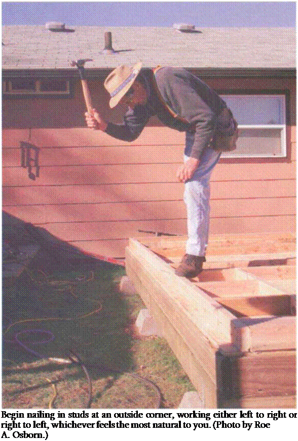
Begin nailing in studs at an outside cor­ner. You’ll find that consistently working either left to right or right to left has a natural feel to you, and over time you’ll develop a rhythm to nailing in studs that involves not only your arms and hands but also your entire body (see the photo at right). Even your feet can be trained to move studs into position for nailing. Framing can become like a dance, where every movement is coordinated and flows into the next. (I have had it hap­pen that my movements became so fluid that time seemed to stand still as I nailed down the plate line. Two of my children are professional dancers. They tell me the same thing often happens to them during a dance production.)

Corners and channels can be built in different ways, depending on the size of the wall and local preferences (see the drawing on p. 116). A three-stud corner is the most basic configuration. If you prefer, you can save wood by building either a two-stud corner or a blocked-up corner. With a two-stud corner, the first

Layout Methods

Use the Correct Order

When you perform the layout, follow a prioritized order. For example, trimmer and king studs for doors and windows take priority over studs. That is because if a stud falls on the location of a trimmer or king stud, then the stud is eliminated. Using a certain order for layout also helps you keep track of where you were if you are pulled off layout and have to come back later to pick up where you left off. The order should be doors and windows first, then bearing posts, backers and corners, then hold- downs—followed by special studs like medicine cabinet studs, then regular studs, and finally miscellaneous framing, such as blocks.

Align Framing Members

It is good practice when laying out studs to align the roof trusses, floor joists, and studs. This is not entirely possible in most cases because the studs are typically 16” O. C., while the roof trusses or rafters are 24” O. C. However, you will at least line up every third truss or rafter. If the studs are 24” O. C., then they need to align with the trusses or rafters. Aligning the studs, joists, and trusses or rafters not

only makes good sense structurally, but makes it easier for the plumbers and electricians to run their pipes and wire between floors.

Consult the Roof and Floor Drawings

To start laying out your studs, you need to know the layout of your roof and floor systems. If you are using dimensional lumber, then you can most likely start the layout for your roof and floor wherever it is convenient. If, however, you are using I-joists or roof trusses, the layout will probably be defined on a set of shop drawings provided by the supplier. You should receive a set of these shop drawings before you start laying out your studs, so that you can align wherever possible. Once you have decided on a starting point for your layout in each direction, use the same layout throughout the building. Although it is not structurally necessary to align nonbearing interior walls with multiple floors, it is helpful to have the studs aligned for the plumbers and electricians.

A Word of Caution

Some production framing techniques speed up the layout process, but be careful, if you use them, not to sacrifice quality. For example, instead of using the X with a line next to it to indicate a stud, a single line
can be used to represent the center of the stud. Be careful with this designation, because the studs need to line up with the middle of the wall sheathing. If you figure that you allow 1/8" for expansion between the sheets of sheathing, that only allows п/іб" for nailing each side. You cannot afford to be off by even a small amount and still get enough stud to nail to. If you use this system, you also have to be sure that your framers are competent and can align the studs properly.

Sill Plates and Sill Beams

Very often, a two-inch thick sill plate is fastened to the foundation, and the wooden frame is attached to that. This sill plate is usually bolted to the foundation all around its perimeter. Yet another neighbor, Chris Ryan — we live in a community of owner-builders — did this at his new garage. First, he laid a course of ordinary eight-inch concrete blocks around the perimeter of his slab, except where his doors would be, because he wanted to keep his posts (and his cordwood masonry) about eight inches (20 centimeters) off the slab. (Fig. 4.3 is actually a detail from the Ryan garage.) Then, at appropriate locations, he filled block cores with concrete and placed anchor bolts into the fresh mix. (Use any bagged dry concrete mix for this, such as Sakrete® or equivalent.) Anchor bolts are in the shape of a long upper-case letter L, and come in various sizes, but a typical one for this purpose would be eight inches long and one-half-inch in diameter, with the top few inches threaded to receive hex-headed nuts. Chris left the bolts sticking out about 1У2 inches (3.8 centimeters) proud of the top of the blocks.

For an eight – or ten-foot sill plate, place an anchor bolt such that there will be one about six inches (152 millimeters) in from each end, and one in the middle of the planks length. Although PT material will not deteriorate in this application, it is still a good ideal to install a roll of Sill Seal® or equivalent. Sill Seal is a blue foam that comes in a roll, eight inches wide and about one-quarter-inch thick. It will help resist rising damp and will also seal against drafts coming in where the sill plate meets the foundation.

Set the plates on top of the anchor bolts and hit the plate with a hammer at each bolt location to make a mark. Drill a five-eighths-inch (1.6 centimeter) hole through the plate at each mark, and install the plate using flat washers and half­inch nuts. Chris countersunk the holes in the plate to accommodate the washers and nuts, but with most infillings, a nut and bolt assembly protruding a half inch proud of the plate will not present a problem.

On a poured footing or slab, you may wish to place the anchor bolts right in the fresh concrete, but be sure to get them in useful positions. If you do make an error, you can always hacksaw any errant bolts off, and install pins by the expansion shield or strike bolt methods already described.

With traditional timber framing, the sill might be a heavy timber, such as an eight-by-eight or better. Timber framer Steve Chappell tells me that these heavy sills are normally installed first, and the bents are raised up on them, with the mortises and tenons all ready to join each other at the time of raising. Where wind uplift is not a code issue, Steve simply pins these heavy timbers to the foundation. He uses metal foundation straps where required by code. You can jump ahead to Fig. 4.54 to see these straps used in an area prone to earthquakes. Steve feels strongly, as I do, that heavy timber frames have a powerful natural resistance against wind uplift.

Most of “the rest of us” place posts directly down on the foundation (not forgetting the damp-proof course) or use a two-by sill plate, like Chris did at his garage. However, at Log End Cottage, our first timber frame structure, built in 1975, we used heavy ten-by-ten (25.4 by 25.4 centimeter) barn beam sills at the gable ends and full-sized three-by-ten sills along the longer sidewalls. The three – by-tens were fastened to the top of the block wall by the method described for Chris’s garage. With the ten-by-tens, we simply set anchor bolts sticking out two inches, made an impression on the underside of the sill with a good strike of the hammer, drilled the receiving holes, and placed the sill beams onto the foundation over the 1970s equivalent of Sill Seal. This stopped the sill from moving laterally. There is no way that this heavy sill and building is going to leap upward off of the positioning pins.

If code requires that you anchor such heavy timbers down, you will need to use threaded rod set in grouted block cores or into the poured concrete footings. The rod would have to extend eleven inches (28.0 centimeters) for a ten-by-ten (or ten inches if you want to countersink the washer and nut.) Alternatively, you may be able to fasten the girder by other strap fasteners set in the concrete for the purpose — see Joe Zinni’s case study at the end of the chapter — or you might choose the angle iron method, described next.

The angle iron method can be very useful where a doorframe is installed after the rest of the frame is already built. However, you can use the technique in all sorts of applications, so I will spend a little time on it now.

Any good building supply will have galvanized angle iron of various sizes and gauges. Four-foot-long sections are a common item, and they are usually stocked near the truss plates and joist hangers. These inexpensive pieces have a number of round or oval holes on both faces of the angle iron, giving almost infinite flexibility for installing lag screws pretty much anywhere you like. You can cut the angle iron quickly with a hacksaw into useful lengths: eight inches, twelve inches, or whatever.

Подпись: Fig. 4.6: Leaded expansion-shield installation method. Drawing courtesy of Simpson Strong-Tie Co.r Inc. It goes like this: Set the doorframe (or post or sill beam) on the slab, floor, footing or sill. Using a pencil, mark the doorframe’s location on whatever surface you are going to fasten to. Choose a length of angle iron a little shorter than the width of the piece you wish to fasten, set it against the pencil line, and choose a couple of appropriate hole locations. Scribe these with a pencil, using the little piece of angle iron as a template. If the receiving surface is concrete, drill appropriately sized holes for whatever anchor you have chosen (leaded expansion shields with lag screw method or strike bolt method). Fasten the angle iron as shown in Figs. 4.6 or 4.7. If you are fastening to a wooden deck, as in Fig. 5.40 on page 136, just drill the appropriate hole into the wood for the lag screw selected.

Now, set the wooden member up next to the angle iron and, with a pencil, scribe a couple of appropriate hole locations on the post, doorframe, or heavy sill. Drill holes into the wooden member, using the correct diameter and depth for the lag screws chosen. Quarter-inch or flve-sixteenths-inch screws of two to three inches in length are appropriate. I make my holes in the wood about a quarter – inch less than the full length of the screw below the hex head, and I use a drill of about the same size as the solid shaft (not including threads) of the lag screw. When in doubt, use a smaller size. If this is too tight, you can always make the hole a little bigger. If the screw is too loose and doesn’t hold, you will have to drill again nearby, using a smaller hole.

With any lag screwing that you do, it is always wise to test the drill hole size and the screw itself on a piece of similar-species scrap wood. You want a fit that is snug and tight, but not so tight that the wood splits or that it is impossible to turn the screw.

Finally, set the wooden member up again and install the lag screws through the angle iron into the receiving hole in the wood. Snug the screws up with a hex – head ratchet wrench. I particularly like this method when I am unable to lift a post or doorframe over an anchor pin, such as when placing a new member within an existing post-and-beam panel.