Obstacles

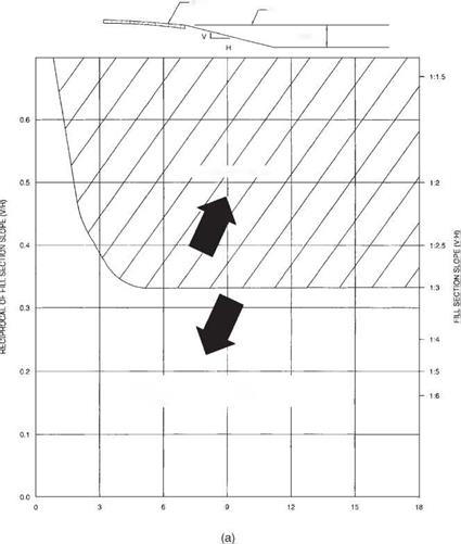
Roadside obstacles include nontraversable terrain and fixed objects, either constructed (such as culvert headwalls or structural supports) or natural (such as trees). Such obstacles account for over 30 percent of highway fatalities. The need for a barrier depends on both the nature of the obstacle and the probability that it will be hit. Table 6.1 lists the major types of obstacles and considerations for barrier warrants. Refer to the clear zone chart (Fig. 6.2) as a guide in determining whether the location of an obstacle constitutes a significant threat.

Obstacles
Подпись: FILL SECTION HEIGHT [ft]
Подпись: BARRIER WARRANTED
Подпись: 3ARRIER NOT WARRANTED FOR EMBANKMENT

ObstaclesFIGURE 6.12 (Continued)

Making Sense of Flexible Metal Cable

There are two main types of flexible metal cable, armor clad and metal clad. Outside, they look about the same. (For a comparison, see the photo on p. 238.) The main difference is that MC cable contains an insulated ground wire so it can ground equipment and tools with a three-prong plug. MC cable assemblies should be used in exposed dry locations, such as garages and basements. PVC-jacketed MC cable can be used outdoors, but it is so expensive that it is rarely used in residences. Note:

Exposed doesn’t mean "exposed to the ele­ments." Here it means visible and accessible— not hidden behind finish walls.

AC cable, on the other hand, contains no ground wire; rather, its metal sheathing serves as an equipment ground. AC should be used only in dry, indoor locations. The thin, uninsu­lated copper aluminum wire inside AC is not a conductor; it’s a bonding wire, which enhances the grounding ability of the armor itself. That is, AC’s grounding path is its metal sheathing.

The NEC allows both MC and AC to be used in branch circuits, but for the reasons just cited, many local codes allow only MC in new con­struction. In the text, MC is the default term for any flexible metal cable.

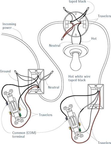
Подпись: I Three-Way-Switch Wiring Подпись: Hot white wireimage515

Подпись: Insert anti-short bushings between wires and sheathing, to protect the wire insulation from the sharp edge of the metal sheathing.
image516

sometimes used as a whip, a short section of exposed cable that connects permanent appli­ances or lighting fixtures to a circuit.

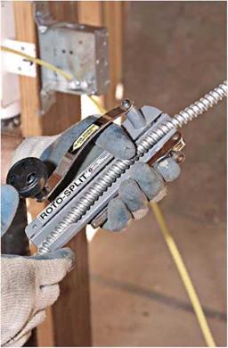
There are at least two ways to cut MC cable. The first method requires looping and squeezing the cable till its coils pucker and then snipping through the pucker with metal shears or diagonal-nose cutters, being careful not to nick the insulated wires inside. The second method is often required by local codes and is far easier: The rotary cable cutter shown in the photo below uses a hand-cranked cutting wheel to cut through metal sheathing. Once the tool cuts through a coil, slide the severed sheathing off the insulated wires inside.

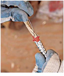
Rough cut lengths of cable about 2 ft. longer than the distance from box to box, to allow for generous loops at turns. After you have removed the metal sheathing, rip free the Mylar® wrap between its outer sheathing and the insulated conductors inside (AC cable has kraft paper sur­rounding its wires). To prevent the severed sheathing from slicing the insulation of individ­ual wires, insert a plastic or fiber anti-short bush­ing between the wires and the sheathing, as shown below right. Note: Anti-short bushings are not required when using UL-listed MC cable clamps, but they are required by code (and man­ufacturers) for AC cable.

image517

Roto-Split cutters cut through armored cable sheathing quickly and cleanly, without damaging the insulation of individual wires inside.

Here’s a representative three-way setup (there are many possible configurations). Whenever you use a white wire as a switch leg, tape it black to indicate that it’s hot. Here, all boxes are nonmetallic.

Подпись: PROTIP Use polyethylene fish tape to pull wires in metal conduits. Flat steel fish tapes can cut and create burrs in metal conduit, and they tend to become jammed up at conduit bends. llll Подпись:

Once you’ve inserted the bushing, attach an appropriate cable connector to the end of the sheathing; most connectors employ a locknut that holds the threaded connector to a metal box. (Pull the BX bonding wire outside the sheathing and wrap it once around the connector screw; the bonding wire doesn’t go into the box.) After the cable connector is secured to the metal box, snip incoming wires so they are roughly 8 in. long. Splice and attach them to devices, as you would wires in nonmetallic cable

Because metal cable is flexible, support it every 6 ft. along its run and within 1 ft. of box connections. Staples should be snug but should not crimp the sheathing. The most common method of attaching cable is stapling it to the undersides or sides of joists where the cable runs parallel. When the cable runs perpendicular to framing, drill 58-in. holes through the center of the studs or joists and feed the cable through.

Note: Flexible metal cable can be punctured by drywall screws, so keep the cable back at least 114 in. from stud or joist edges. Otherwise, use steel nail-protection plates to safeguard the cable.

CONDUIT

There are several types of conduit, including thin-walled electrical metal tubing (EMT), rigid metal conduit (RMC), flexible metal conduit (FMC), and rigid nonmetallic conduit (RNC), which is made of PVC plastic. With metal con­duit, the conduit pipe is the equipment ground. Fittings are specific to each type of conduit and may vary further if the conduit is to be used underground or in high-moisture areas. Most types approved for exterior use will have weather­proof compression fittings. All conduit boxes must also be gasketed to keep moisture out.

Because conduit comes without wires inside, you must pull wire through it. Although wire can usually be pushed easily through straight lengths of conduit 10 ft. or less, use fish tape to pull wires around bends or through longer lengths.

First, use a conduit whose diameter is large enough for the number of wires you need to pull: 52-in. interior diameter (I. D.) conduit will suffice for most runs of 12AWG wire; use 54-in. I. D. con­duit for the heavier wires, such as 8AWG or 6AWG wire, needed for stoves and such. Check your local code requirements. Using pulling com­pound (also called pulling lube) will make the task easier, as will having one person to feed wire and one to pull. THHN wire, whose coating is especially slick, is often specified when pulling is necessary. To keep wires from pulling off the fish tape, bend them tightly over the end of the tape, and wrap well with electrical tape.

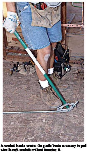
Pull wire only after you’ve attached conduit to boxes. If conduit bends more than the equivalent of four 90° bends between two boxes, you’ll need a pull box in the middle of the run, through which wires can be pulled. Too many bends cre­ates too much friction to overcome and can stress the wire too much. Such boxes give you access to the middle of the run. To shape bends, use a conduit bender, which slides over the con­duit. Bend the conduit, pushing down heavily on the shoe and bend till you achieve the desired curve: For 52-in. EMT conduit, a radius of about 552 in. is usual for a 90° bend. The bender will have arrows that indicate turning radiuses. Use a hacksaw to cut metal conduit; then use a debur – ring tool to smooth the cut ends and remove any metal spurs that could nick the conductor insulation.

Support EMT conduit at least every 10 ft. and within 3 ft. of termination. Connections within boxes are essentially the same as those for Romex cable, the principal difference being that

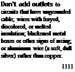
Подпись: TIPПодпись: Don't add outlets to circuits that have ungrounded cable; wires with frayed, discolored, or melted insulation; blackened metal boxes or other signs of arcing; or aluminum wire (a soft, dull silver) rather than copper. 1111 image519

the conduit itself, because it is metal, provides the grounding. To ground individual outlets, run a grounding pigtail from the grounding screw on the device to the metal box.

Speed of the Rollers

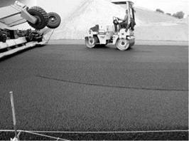
The speed of the rollers should be controlled and should be slow. According to the NAPA SMA handbook QIS 122, the speed of a roller during rolling must not exceed 5 km/h. In one of the British guidelines, the speed of the rollers should normally be between 4 and 6 km/h (SEHAUC, 2009).

Rolling with vibration at a reduced speed improves the effectiveness of compaction. However, doing so may lead to crushing particles and squeezing mastic out on the sur­face of a layer. Therefore great caution should be exercised, and vibration should be turned off if need be. Rollers with a speed control option enable automatic control to disengage vibrations during braking and changing direction. It should be kept in mind that rollers with speed control require a longer braking distance and skillful control.

Rafter or Truss

Rafter or truss layout, like floor joist layout, is relatively easy compared with wall layout. Sometimes it is helpful to lay out for rafters or trusses on the top of the double plate so that once the wall is standing, the layout will already be done, and you won’t have to do it from a ladder. (See “Rafter layout on walls before the wall is stood up" photo.)

Special layout is often required for ceiling can-lights. Check on necessary clearance to make sure you provide enough room.

Roof layout is the process of taking the information given on the plans and writing enough instructions on the double plate for the roof framer to spread and nail the rafters or trusses.

Use the same reference points established for floor and wall building for starting layout on the roof.

Roof rafters and trusses are sometimes 24" O. C. as compared with 16" O. C. for floors and walls. In that case, only every third truss or rafter will be over a stud.

Before layout is started, check plans for openings in the roof required by dormers, skylights, chimneys, etc.

For roof trusses, lay out according to truss plan, especially for hip-truss packages.

Roof Layout Language

Rafter or truss

X

Tail rafter or truss

T

Double rafter or truss

XX

Roof Layout Steps

1. Lay out for doubles, trimmers, and tail rafters or trusses.

2. Lay out for other rafters or trusses.

Rafter layout on walls before the wall is stood up

Conclusion

Writing layout is just like writing anything else. If the person reading it understands what you want to say, then you’ve done a good job. When you are done with the layout, take a look at it to make sure you can read it. If your writing is not showing up clearly, you might try a different brand of carpenter pencil. There are different leads, and some write better than others, depending on the condition of the wood. You can also use indelible marking pens, which are especially good on wet lumber.

Review the layout with the framer who will be reading it before he starts. If a framer doesn’t understand your layout, it takes more time for him to try to figure it out than for you to explain it to him. A little extra time spent on layout is usually a good investment. It’s not easy taking information from all the different sources that combine in the construction of a building and making it legible for framing, but if the layout is communicated clearly, it will help the framers do their work in an organized and productive manner.

Embankments

As indicated in Fig. 6.12, the main factors considered in determining the need for barriers are the embankment height and the side slope. These criteria are based on studies of the severity of encroachments on embankments as compared with impacts with roadside barriers. The figure does not include the probability of an encroachment or relative costs. Some states have made their own studies and developed charts having a series of curves for different traffic densities.

Подпись: SHOULDER
Подпись: TRAVELED WAY
Embankments
Подпись: BARRIER WARRANTED
Подпись: BARRIER NOT WARRANTED FOR EMBANKMENT. HOWEVER, CHECK BARRIER NEED FOR OTHER ROADSIDE OBSTACLES.

EmbankmentsFILL SECTION HEIGHT (m)

FIGURE 6.12 Embankment warrants based on comparative risk analysis. (a) SI units; (b) U. S. Customary units. (From Roadside Design Guide, AASHTO, Washington, D. C., 2002 and 2006, with permission)

Sequence

Various compaction sequences are adhered to. Generally speaking, every road-en­gineering company works out its own procedure after some time. By and large, the standard rule states that the paver is followed by static rollers first and then by vibra­tory rollers. Final passes are always carried out by static rollers, which finally level the surface, removing traces of rolling from it (the so-called finishing). When using

image103

FIGURE 10.11 The particular way rollers approach the paver, with a turn being made right behind the paver. (Photo courtesy of Konrad Jablotiski.)

rollers with new types of vibration, it is worthwhile to consider the manufacturer’s

suggestions.

One of the more interesting techniques of rolling consists of the first roller behind the paver (the breakdown roller) making a slight turn when it approaches the paver (Figure 10.11). The remaining rollers operate without making the turn by simply reversing direction. This technique, among others applied in the Kompaktasphalt, is aimed at achieving better layer smoothness.

STEP 3 SET THE WINDOWS AND DOORS

The setting process anchors the windows and doors in their final positions. Complete instal­lation happens later, when we move inside the house and work on the interior trim. The windows and doors used in affordable hous­ing are mainly vinyl and vinyl clad, though aluminum-clad frames are still installed in some areas. Some codes require that window frames be clad with white vinyl; check with your local building department. Dark-colored vinyl absorbs more solar heat and, as a result, tends to deteriorate faster. On the other hand, dark-colored aluminum cladding holds up well in sunny areas.

Both vinyl and aluminum-clad windows come with a nailing flange on the outside of the window frame; the flange greatly simplifies the installation process. The most popular styles are single hung (the bottom sash moves up and down), double hung (both sashes move up and down), and sliding (one sash slides to the side). Windows with a built-in J-channel, or channel surround, make it easy to hide the ends of vinyl and other siding without the use of extra trim.

Windows in affordable houses should defi­nitely be double-glazed. The heat loss and gain through single-glazed windows is considerable. In very cold or very hot climates, windows with low-E coatings offer even more energy savings. For more information on energy-efficient glaz­ing, see Resources on p. 279.

Setting a window

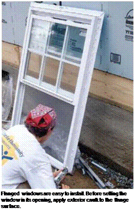
Flanged windows are the easiest windows to in­stall, but windows that come with exterior trim instead of flanges are fairly easy as well. The main difference is that you nail through the exterior trim instead of through the flanges. No matter which type of window you use, it’s good to have two people for this job—one inside the house and one outside. There are three basic steps involved in setting a window:

not to damage the vinyl frame by hitting it with your hammer. When I’m building in rainy climates, I make one more seal all around the windows by running a strip of waterproof tape over the flange and onto the housewrap. It may be overkill, but who wants to tear off siding to repair a leaky window in the middle of a rainstorm?

Setting a prehung exterior door

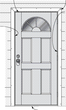
Подпись:Подпись: Plumb the frame with a level. Before nailing the flange to the wall, fine-tune the window's position so the side of the frame is plumb.STEP 3 SET THE WINDOWS AND DOORSПодпись:Exterior doors are often prehung units that include jambs, a threshold, and wood exterior trim. I buy doors predrilled for both the house lockset and the deadbolt. Given the option, I also choose a door with a double-glazed glass window to bring more light into the house.

1. Make sure there is a [2]/8-in. gap between the door and the door frame.

If you live in a high-wind area, help protect your home by cutting pieces of plywood to fit over every window and store them in your garage. When the big blow comes you can screw these pieces in place over the windows.


Take note of which way the plans say the door should open, and make sure the door you or­dered swings the right way (see the illustration at right). Most exterior doors open inward. Also, make sure the door jamb is the proper width for the wall. A 2×6 wall takes a wider jamb than a 2×4 wall does. There are four basic steps involved in setting a prehung door:


WHICH WAY DOES THE
DOOR SWING?


Stand here with your back to the door hinges.


1. Flash the doorsill. The sides and top of the rough opening can be flashed in the same way as a window. With an exterior door, sill flashing is essential if you want to prevent rot beneath the threshold. I prefer to use 12-in.- wide aluminum flashing for this application, though heavy tar paper also works well.

Cut the flashing about 6 in. longer than the width of the rough opening so it can cover


Most suppliers use the above method to determine which way a door opens.


the threshold area completely and extend several inches up each trimmer stud. Cut the flashing as necessary to create ears that fold onto the subfloor and over the exterior wall sheathing. You can keep the flashing in place with a few galvanized roofing nails.

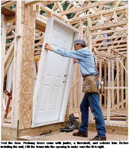
2. Test-fit the door. When working with a prehung door, your primary concern is to set it so that it opens and closes with ease. Fortunately, this is pretty easy to do. Once you’ve removed any materials used to protect the door during shipping and any device used to hold the door secure in its jamb, check the fit of the door in its opening. It should fit easily (see the top photo on the facing page).

3. Set the door in place. Run a bead of sealant on the back of the door trim and a couple of heavy beads across the bottom of the rough opening on the flashing where the threshold will sit. Then set the frame in its opening. From the inside, adjust the frame so that there’s a gap of about ‘/s in. all the way around the door. This will allow the weatherstripping on the door frame to seal properly. Secure the door in the opening by


STEP 3 SET THE WINDOWS AND DOORS

Exterior wall


3. Nail through the jamb into the trimmers above and below the hinge locations. Insert shims as necessary to keep the jamb straight. Use 8d finish nails or 2-in.


4. Nail through the jamb on the lock side, using shims to keep the jamb straight. Keep nails out of the lock and deadbolt area.

Set all nails or countersink screws, then fill recesses with wood putty.


screws


5. Drive long screws (provided with the door) through the hinges and jamb and into the trimmer.


Threshold


Keep checking as you work to make sure the door opens and closes with ease.


STEP 3 SET THE WINDOWS AND DOORSSTEP 3 SET THE WINDOWS AND DOORSSTEP 3 SET THE WINDOWS AND DOORSSTEP 3 SET THE WINDOWS AND DOORS

Подпись: Test the door. Prehung doors come with jambs, a threshold, and exterior trim. Before installing the unit, I tilt the frame into the opening to make sure the fit is right.

driving a 16d finish nail through each corner of the exterior trim and into the sheathing and studs. (Alternatively, you can drive 3-in.- long trim-head screws.)

4. Finish fastening the door. Check the door again to see that it opens and closes with ease. If it does, then drive more 16d finish nails (or screws) 2 ft. o. c. all the way around the trim. Set all nails or screws about У) in. below the surface of the wood so they can be hidden by putty and covered with paint. Drive 8d finish nails or 2-in.-long screws through the hinge side of the jamb and into the trimmer near each hinge. If the jamb is not tight against the trimmer, slip in a shim to prevent the jamb from bowing. Shim and nail through the jamb on the lock side next, but be sure to keep nails away from the lock and deadbolt area. Finally, drive the long screws that are included with the door frame through the hinges and the jamb and into the trimmer. These help hold the entire assembly in place.

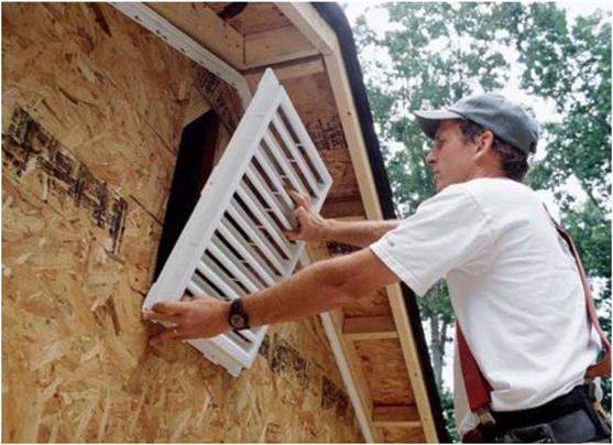
STEP 3 SET THE WINDOWS AND DOORSInstall the attic vent. Vinyl siding panels can’t be installed until the vents, outlet boxes, and other wall elements are in place. This vent has flanges for easy installation. House – wrap and flashing go on before final installation.

Other Tasks that Can Be Done Along with Layout

Some items can be attended to while you are performing the layout. One is to cut a kerf in the bottom of the bottom plate at door thresholds when they are sitting on concrete. This kerf (about half the thickness of the plate) allows you to cut out your bottom plate after the walls are standing without ruining your saw blades on the concrete. (See “Kerf cut [threshold cut]" photo.)

You can take care of another item while drilling the bottom plate to install over anchor bolts. When the bottom plate is taken off the bolts to do the layout, it can be turned over and accidentally built into the wall upside-down. This problem can be prevented by using a carpenter crayon to mark “UP" on the top

Kerf cut (threshold cut)

of the plate before it is removed from the bolts. Angle walls have the same potential for getting built with the plates backward. You can also mark them as they are being laid out.

Layout Tools

There are some tools that can help with layout, particularly with multi-unit or mass production – type framing. One of these is the channel marker, a template made to assist in laying out corners and backers. Another is a layout stick. The layout stick is 491/21′ long and is placed on the plates to act as a jig for marking studs. (See “Channel marker and layout stick" photo.)

oist Layout

Floor Joist

Joist layout is relatively easy compared with wall layout. It uses the same basic language as walls.

Special layout for joists includes the area under the toilet and shower drain. It is easier to move a joist a couple of inches or even to add a joist than to come back and "header-out" a joist because the plumber had to cut it up to install pipes. On larger buildings, there may be shop drawings for the floor joists that can be used for your layout. The shop drawings should show the locations of openings and how they should be framed. (See “Joist Layout Language" illustration.)

Channel marker & layout stick

Joist Layout Principles

Joist layout is the process of taking the information given on the plans and writing enough instructions on the top of the rim joist or double plate so the joist framer can spread and nail the joists without asking any questions.

Where possible, we want joists, studs, and rafters to set directly over each other.

Before layout is started, establish reference points in the building for measuring both directions of layout and use those points for joist, stud, and rafter/truss layout throughout the building. Check the building plans for special joist plan or rafter/truss plans
indicating layout. Select a reference point which allows you to lay out in as long and straight a line as possible, and which ensures that a maximum number of rafters/trusses are directly supported by studs.

Check plans for openings in the floor required for stairs, chimneys, etc.

Check plans for bearing partitions on the floor. Double joists under bearing partitions running parallel.

Check locations of toilets to see if joists must be headed-out for toilet drain pipes.

Joist Layout Language

Joist

Tail joist Double joist

Beam

Joist Layout Steps

1. Layout for double joist, trimmer joist, and tail joist.

2. Layout for other joists.

Preventive maintenance

There are two basic categories of maintenance: corrective maintenance and preventive maintenance. Corrective maintenance is performed when the sys­tem experiences in-service failures. Corrective maintenance often involves the needed repair, adjustment, and replacement to restore the failed system back to its normal operating condition. Therefore, corrective maintenance can be regarded as repair, and its stochastic characteristics are describable by the re­pair function, MTTR, and other measures discussed previously in Secs. 5.3.1 through 5.3.3.

On the other hand, preventive maintenance, also called scheduled mainte­nance, is performed in a regular time interval involving periodic inspections,
even if the system is in working condition. In general, preventive maintenance involves not only repair but inspection and some replacements. Preventive maintenance is aimed at postponing failure and prolonging the life of the sys­tem to achieve a longer MTTF for the system. This section will focus on some basic features of preventive maintenance.

From the preceding discussions of what a preventive maintenance program wishes to achieve, it is obvious that preventive maintenance is only a waste of resources for a system having a decreasing or constant hazard function because such an activity cannot decrease the number of failures (see Example 5.7). If the maintenance is neither ideal nor perfect, it may even have an adverse impact on the functionality of the system. Therefore, preventive maintenance is a worthwhile consideration for a system having an increasing hazard function or an aged system (see Problems 5.18 and 5.19).

Ideal maintenance. An ideal maintenance has two features: (1) zero time to com­plete, relatively speaking, as compared with the time interval between mainte­nance, and (2) system is restored to the “as new” condition. The second feature often implies a replacement.

Let tM be the fixed time interval between the scheduled maintenance, and ps, M(t) is the reliability function with preventive maintenance. The reliability of the system at time t, after k preventive maintenances, with ktM < t < (k + 1)tM, for k = 0,1,2,…, is

ps, M(t) = P {no failure in(0, tM], no failure in(tM,2 tM],…,

no failure in((k – 1)tM, ktM], no failure in(ktM, t]}

Preventive maintenance

П no failure in ((i

i=1


1)tM, itM], no failure in (ktM, t]


=P


Подпись: (5.27)= [ps(tM)]k X ps(t – ktM)

where ps, M(t) is the unmaintained reliability function defined in Eq. (5.1a).

The failure density function with maintenance fM (t) can be obtained from Eq. (5.27), according to Eq. (5.2), as

Подпись: f M (t)

Preventive maintenance Подпись: [ ps (tM )]kft (t - ktM ) Подпись: (5.28)

d [ps, m(t)]
dt

for ktM < t < (k + 1)tM, with k = 0, 1, 2,_______________________ As can be seen from Eqs. (5.27) and

(5.28), the reliability function and failure density function with maintenance in each time segment, defined by two consecutive preventive maintenances, are scaled down by a factor of ps(tM) as compared with the proceeding segment.

Preventive maintenance

Preventive maintenanceWith Scheduled Maintenance

Without Scheduled Maintenance

time

Figure 5.12 Reliability function with and without preventive maintenance.

The factor ps(tM) is the fraction of the total components that will survive from one segment of the maintenance period to the next. Geometric illustrations of Eqs. (5.27) and (5.28) are shown in Figs. 5.12 and 5.13, respectively. The envelop curve in Fig. 5.12 (shown by a dashed line) exhibits an exponential decay with a factor of ps(tM).

Similar to an unmaintained system, the hazard function with maintenance can be obtained, according Eq. (5.3), as

hM (t) = Mfor ktM < t < (k + 1)tM, k = 0,1,2,… (5.29)

Подпись: Figure 5.13 Failure density function with ideal preventive maintenance.

Ps, M(t – ktM)

The mean time-to-failure with maintenance MTTFm can be evaluated, ac­cording to Eq. (5.18), as

г ж f-(k+1)tu

MTTFm = / Ps, m (t) dt = ^/ Ps, m (t) dt

Preventive maintenance Подпись: (5.30)

•JO k=o ’ k^M

Подпись: MTTFM = Подпись: [Ps(tM)]k k=0 Подпись: ptM I PS(T ) dT O Подпись: J0M PS(T) dT 1 - Ps(tM)
Подпись: (5.31)

By letting t = t – ktM, the preceding integration for computing the MTTFm can be rewritten as

using 1/(1 – x) = 1 + x + x2 + x3 + x4 + …, for 0 < x < 1.

Подпись: Ps, M (t) Ps(t) Подпись: [ Ps(tM )]kPs (t Ps(t) Preventive maintenance Подпись: 1 Подпись: for ktM < t < (k + 1)tM, k = 0, 1, 2,... (5.32)

A preventive maintenance program is worth considering if the reliability with maintenance is greater than the reliability without maintenance. That is,

Подпись: Ps, M (ktM ) Ps(ktM ) Preventive maintenance Подпись: for k = 0, 1, 2, ... Подпись: (5.33)

Letting t = ktM and assuming ps(0) = 1, the preceding expression can be simplified as

Similarly, the implementation of a preventive maintenance program is justifi­able if MTTFm > MTTF or hM(t) > h(t) for all time t.

Example 5.7 Suppose that a system is implemented with preventive maintenance at a regular time interval of tM. The failure density of the system is of an exponential type as

ft(t) = Xe-xt for t > 0

Assuming that the maintenance is ideal, find the expression for the reliability function and the mean time to failure of the system.

Solution The reliability function of the system if no maintenance is in place is (from Table 5.1)

ps(t) = e~lt for t > 0

The reliability of the system under a regular preventive maintenance of time interval tM can be derived, according to Eq. (5.27), as

Ps, M(t) = (e-ltM)k x e-x(t-ktM-1 for ktM < t < (k + 1)tM, k = 0,1,2,…

Подпись: which can be reduced to

Ps, M(t) = e lt for t > 0

Подпись: MMTFM Preventive maintenance Подпись: 1(1 - e-XtM) 1 1 — e-xtM X

The mean time to failure of the system with maintenance can be calculated, according to Eq. (5.31), as

As can be seen, with preventive maintenance in place, the reliability function and the mean time to failure of a system having an exponential failure density (constant failure rate) are identical to those without maintenance.

Example 5.8 Consider a system having a uniform failure density bounded in [0, 5 years]. Evaluate the reliability, hazard function, and MTTF for the system if a preventive maintenance program with a 1-year maintenance interval is implemented. Assume that the maintenance is ideal.

Solution The failure density function for the system is

ft(t) = 1/5 for 0 < t < 5

From Table 5.1, the reliability function, hazard function, and MTTF of the system without maintenance, respectively, are

Ps(t) = (5 — t)/5 for 0 < t < 5

h(t) = 1/(t — 5) for 0 < t < 5

and MTTF = 5/2 = 2.5 years

Подпись: and Preventive maintenance

With the maintenance interval tM = 1 year, the reliability function, failure density, hazard function, and the MTTF can be derived, respectively, as

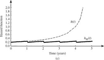
Referring to Fig. 5.6, the hazard function for the system associated with a uniform failure density function is increasing with time. This example shows that the MTTFm is larger than the MTTF, indicating that the scheduled maintenance is beneficial to the system under consideration. Furthermore, plots of the reliability, failure density, and hazard function for this example are shown in Fig. 5.14.

In the context of scheduled maintenance, the number of maintenance ap­plications KM before system failure occurs is a random variable of significant

Preventive maintenance

Preventive maintenance

Preventive maintenance

Figure 5.14 Reliability function (a) with [ps, M(t)] and without [ps(t)] pre­ventive maintenance, failure density function (b) with [ f m(t)] and without [ft(t)] preventive maintenance, and hazard function (c) with [Hm(t)] and without [H(t)] preventive maintenance for Example 5.8.

importance. The probability that the system will undergo exactly k preventive maintenance applications before failure is the probability that system failure occurs before (k + 1)tM, which can be expressed as

qk = [ Ps(tM )]k [1 – Ps(tM)] for k = 0,1,2,… (5.34)

Подпись: ps(tM ) 1 - ps(tM) Подпись: (5.35)

Подпись: TO ps(tM)]J3 k X [ps(tM)]k k = 1
Подпись: E ( KM ) = Y, k x qk = [1 k=0

which has the form of a geometric distribution. From Eq. (5.34), the expected number of scheduled maintenance applications before the occurrence of system failure is

Подпись: Var(KM) = ]Tk2 x qk - E2(KM) k=0 Подпись: [1 - ps(tM)]£k2[ps(tM)]k k = 1 Подпись: ps(tM) 2 1 - ps(tM)_

and the variance of KM is

Подпись: ps(tM) 2 1 - ps(tM)_ Подпись:ps(tM )[1 + ps(tM )]
[1 – ps(tM)]2

ps(tM )

[1 – ps(tM)]2

Preventive maintenance Подпись: x (1 - x)2 Подпись: i2xi i=1 Подпись: x(1 + x) (1 - x)3 Подпись: (5.37)

The algebraic manipulations used in Eqs. (5.35) and (5.36) employ the following relationships under the condition 0 < x < 1:

Example 5.9 Referring to Example 5.7, having an exponential failure density func­tion, derive the expressions for the expected value and variance of the number of scheduled maintenance applications before the system fails.

Подпись: E ( KM ) Подпись: ps (tM ) 1 - ps(tM) Подпись: e-ltM 1 1 1 — £~^м Q^M — 1 Q^M/MTTF 1

Solution According to Eq. (5.35), the expected number of scheduled maintenance ap­plications before failure can be derived as

Подпись: Var( KM ) Подпись: ps (tM ) [1 - ps(tM)]2 Подпись: g—XtM (1 - e-XtM )2 Подпись: QMM (ektM - 1)2 Подпись: etM/MTTF (etM/MTTF - 1)2

The variance of the number of scheduled maintenance applications before failure can be derived, according to Eq. (5.36), as

Time variations of the expected value and standard deviation of the number of sched­uled maintenance applications before failure for a system with an exponential failure density function are shown in Fig. 5.15. It is observed clearly that, as expected, when the time interval for scheduled maintenance tM becomes longer relative to the MTTF,

Подпись: Figure 5.15 Time variations of the expected value and standard deviation of the number of scheduled maintenance applications before failure for a system with an exponential failure density function, as in Example 5.9.

the expected number of scheduled maintenance applications E(Km) and its associ­ated standard deviation a ( Km ) decrease. However, the coefficient of variation Q ( Km ) increases. Interestingly, when tM/MTTF = 1, E(Km) = 1/(e — 1) = 0.58, indicat­ing that failure could occur before maintenance if the scheduled maintenance time interval is set to be MTTF under the exponential failure density function.

Example 5.10 Referring to Example 5.8, with a uniform failure density function, compute the expected value and standard deviation of the number of scheduled main­tenance applications before the system fails.

Подпись: E( KM ) Подпись: Ps (tM ) 1 — Ps(tM) Подпись: 4/5 4/5 1 - (4/5) = 1/5

Solution According to Eq. (5.32), the expected number of scheduled maintenance ap­plications before failure can be derived as

Подпись: Var( KM )Подпись: 20

Preventive maintenance

The variance of the number of scheduled maintenance applications before failure can be derived, according to Eq. (5.33), as

The standard deviation of the number of scheduled maintenance applications before failure for the system is V20 = 4.47 scheduled maintenance applications.

Imperfect maintenance. Owing to faulty maintenance as a result of human error, the system under repair could fail soon after the preventive maintenance application. If the probability of performing an imperfect maintenance is q, the reliability of the system is to be multiplied by (1 – q) each time maintenance is performed, that is,

Ps, m (t | q) = [(1 – q) ps(tM)]kPs (t – ktM) for ktM < t < (k + 1) M k = 0, 1,2,…

(5.38)

Подпись: Ps,M(ktM | q) Ps(ktM ) Preventive maintenance Подпись: for k = 0, 1, 2, ... Подпись: (5.39)

An imperfect maintenance is justifiable only when, at t = ktM,

Example 5.11 Refer to Example 5.7, with an exponential failure density function. Show that implementing an imperfect maintenance is in fact damaging.

Solution By Eq. (5.39), the ratio of reliability functions with and without imperfect maintenance for a system with an exponential failure density is

Подпись: (1 - q)k < 1 for k > 1Ps, m(ktM | q) _ (1 k (e Шм

Ps(ktM) =( q) в-шм

This indicates that performing an imperfect maintenance for a system with an expo­nential failure density function could reduce reliability.

5.3.5 Supportability

For a repairable component, supportability is an issue concerning the ability of the components, when they fail, to receive the required resources for car­rying out the specified maintenance task. It is generally represented by the time to suPPort (TTS), which may include administrative time, logistic time, and mobilization time. Similar to the TTF and TTR, TTS, in reality, also is randomly associated with a probability density function. The cumulative dis­tribution function of the random TTS is called the suPPortability function, rep­resenting the probability that the resources will be available for conducting a repair task at a specified time. Also, other measures of supportability include the mean time to suPPort (MTTS), TTSP, and suPPort success, similar to those defined for maintainability, with the repair density function replaced by the density function of the TTS.
OFFICES AND PUBLIC BUILDINGS

Offices and public buildings may be allowed to have only one bathroom, sub­ject to the size and use of the building. Refer to Figure 9.2, line number 6, for a complete description of possible options in using a single bathroom. The table in Figure 9.8 shows you sizing information for offices and public build­ings where multiple bathrooms are used. Feel up to another sizing example? Well, let’s try a couple with the table in Figure 9.8.

Schools:

Average

Bach 15

1 Fixture Each 15 1 Fixture

Pre-School,

Daily

children or

children or

Day Care or

Attendance

fraction

fraction

Nursery

thereof

thereof

Schools:

Average

One drinking fountain for each 3

Elementary &

Daily

classrooms, but not less than

Secondary

Attendance

Persons (total)

Male

Female

Persons (total)

Male

Female

one each floor

1-50

2

2

1-120

1

1

51-100

3

3

121-240

2

2

101-150

4

4

For each

151-200

5

5

additional 120

For each

persons over

additional 50

240, add

1

1

persons over 200, add

1

1

Подпись: CALCULATING MINIMUM PLUMBING FACILITIES ■ 175

FIGURE 9.7 ■ Minimum fixtures for elementary and secondary schools. (Courtesy of Standard Plumbing Code)

”I

O’,


Подпись: PLUMBER’S AND PIPE FITTER’S CALCULATIONS MANUAL

Office6 and

100 sq ft

Drinking fountains

public buildings

per person

Persons (total)

Male

Female

Persons (total)

Male

Female

Persons

Fixtures

1-15

1

1

1-15

1

1

1-100

1

16-35

1

2

16-35

1

2

101-250

2

36-55

2

2

36-60

2

2

251-500

3

56-100

2

3

61-125

2

3

Not less than one

101-150

3

4

For each

fixture each floor

For each

additional 120

subject to access.

additional 100

persons over

persons over

125 add

1

1.57

150 add

1

1.57


FIGURE 9.8 ■ Minimum fixtures for offices and public buildings. (Courtesy of Standard Plumbing Code)

Okay, assume that the public building we are working with will be rated for 75 people. What are the fixture requirements? We will need two toilets in the male restroom and three in the female restroom. How many lavatories are required? Two lavatories are needed in the male restroom and three are re­quired in the female restroom. One drinking fountain is required, but others may be required if the building has more than one floor level, since a fountain is required on each floor of the building. That wasn’t too hard, was it? Now let’s try an example with a larger occupancy load.

In this example, assume that there will be 250 occupants. The amount of water closets needed in the male restroom is four. How many are need in the female restroom? Looks like 5V2 toilets, right? Well, it is, but you have to round up to the next nearest whole number. In other words, you would need six toilets in the female restroom. What are the needs for lavatories? The male restroom requires four lavatories, and the female lavatory need is six. How many drinking fountains are needed in a building that has only a single floor? Three fountains are required.