Posted by admin on 19/ 11/ 15
The number of rollers, their types, and number of passes should be selected with regard to the SMA gradation, layer thickness, weather conditions, and the planned paving speed. Obviously the rollers should be in good working order, able to work at low and constant speeds.
The Minimum number of rollers to compact one layer one lane wide is two or three. Many nations’ guidelines stipulate diverse requirements for the numbers of rollers, mainly stating that one should use rollers weighing more than 9-10 tons each. If three rollers are in use, two of them should be responsible for the majority of the compaction, and one should be the finisher. Extra rollers should be added in case of
|
TABLE 10.1
A Summary of the Usefulness of Equipment for SMA Placement
steel pneu- Triple – matic Wheels Tire
|
rollers
|
rollers
|
|
steel Tandem rollers
|
|
combi rollers
|
|
|
|
|
|
Directional
|
|
|
|
|
operation
|
static
|
static
|
static
|
vibration
|
vibration
|
oscillation
|
static
|
vibration
|
|
SMA 0/11 mm and
|
Yes
|
No
|
Yes
|
Yes
|
Yes
|
Conditionally
|
No
|
No
|
finer
Source: Based on M VA, Merkblatt fur das Verdichten von Asphalt (M VA), Ausgabe, FGSV Koln,
Germany, 2005.
|
problems with reaching the design layer density. Table 10.1 shows an overall summary of the usefulness of equipment for SMA placement based on German compaction guidelines M VA 2005.
Posted by admin on 19/ 11/ 15
Breakaway supports for luminaires are usually a cast-aluminum transformer-type frangible base, a slip base, or frangible couplers. These devices have been developed to activate when loaded in shear by impacts at a bumper height of about 20 in (500 mm). If the supports are located so that they may be impacted at a greater height, the performance may not be as intended. Thus, foreslopes between the roadway and the support should be limited to 1:6 or flatter. The mast arm of a falling support will usually rotate away from the roadway. However, the danger of falling poles striking pedestrians, bicyclists, and other motorists should be considered.
Breakaway supports are suitable for poles that do not exceed 60 ft (18.5 m) in height and 1000 lb (450 kg). Foundations must be designed for the surrounding soils to prevent the foundation from pushing through the soil. From a roadside safety perspective, a preferred method for lighting major intersections is to use high-mast lighting, because fewer supports are required and they can be located farther from the roadway. Supports located in the clear zone should be protected with a suitable traffic barrier.
Posted by admin on 19/ 11/ 15
Historically, chemical analysis of water was achieved by titration methods. It is, practically, impossible to use these on water containing a pollutant at a low concentration due to the need to collect a very large volume of water that can be concentrated to permit a weighable amount of chemical to be obtained at the end of the procedure. Also, such procedures are very time-consuming and operator sensitive. Therefore, modern analysis is based on electrical, atomic and spectrographic techniques.
The most common analytical techniques suitable for determination of the presence of selected pollutants are synthesised in Table 7.3.
|
Table 7.3 Analytical techniques suitable for determination of the presence of selected pollutants
|
Technique
|
Detection limit level
|
Basic
|
Common
|
Platinum
|
Organic
|
|
|
cations*
|
heavy
|
group
|
compounds
|
|
|
|
metals)
|
elementsf
|
(e. g. PAH and their derivates, HCB, PCB)
|
|
Gas Chromatography
|
Depends on sample
|
|
|
|
X
|
|
(GC)
|
preparation and detector used
|
|
|
|
|
|
Liquid Chromatography
|
Depends on sample
|
|
|
|
X
|
|
(LC)
|
preparation and detector used
|
|
|
|
|
|
Atomic Absorption
|
mg. l-1 or pg. l-1
|
X
|
X
|
|
|
|
Spectrometry (AAS)
|
(ppm or ppb)
|
|
|
|
|
|
Inductively Coupled
|
pg. l-1 or ng. l-1
|
|
X
|
X
|
|
|
Plasma (ICP)
|
(ppb or ppt)
|
|
|
|
|
|
Molecule Absorption
|
mg. l-1 or pg. l-1
|
X
|
X
|
|
|
|
spectrometry in the UV – VIS
|
(ppm or ppb)
|
|
|
|
|
|
environment
|
|
|
|
|
|
|
(UV-VIS) Ion Exchange
|
Depends on sample
|
X
|
X
|
|
|
|
Chromatography
|
preparation and
|
|
|
|
|
|
(IEC)
|
detector used
|
|
|
|
|
* = include sodium, potassium, calcium, barium and magnesium.
X = include iron, copper, zinc, cadmium, lead, chromium, nickel, cobalt and vanadium. f = here include rhodium, palladium, iridium and platinum. PAH = polyaromatic hydrocarbons, HCB = hexachlorobenzene, PCB = polychlorinated biphenyls. ppm = parts per million (10-6). ppb = parts per billion (10-9). ppt = parts per trillion (10-12).
|
Posted by admin on 19/ 11/ 15
  The Portland demonstration subdivision was arranged in clusters of four detached units. The city allowed one 1 1/2-inch PVC water line to run from the main to each cluster and 3/4-inch PVC from there to each unit. This was instead of one 1-inch line from the main to each unit. Cost savings amounted to $32 per unit. The Portland demonstration subdivision was arranged in clusters of four detached units. The city allowed one 1 1/2-inch PVC water line to run from the main to each cluster and 3/4-inch PVC from there to each unit. This was instead of one 1-inch line from the main to each unit. Cost savings amounted to $32 per unit.
Rough plumbing was installed in a trough above the slab so the plumber would make only one site visit. All plumbing was clustered to reduce DWV and supply pipe lengths. A standardized DWV plumbing "tree" was used; therefore, much of the DWV system could be prefabricated. The plumbing wall was prefabricated with supply pipe and DWV installed. Polybutylene plastic pipe was used instead of copper. Total plumbing cost savings averaged $182 per unit.
 
Polybutylene supply pipe, fiberglass bathtubs, and cultured marble lavatory/vanity tops were used instead of copper pipe, cast iron bathtubs with ceramic tile surrounds, hardboard vanity tops, and ceramic lavatories. Total cost savings amounted to $367 per unit.
|
Tulsa, Oklahoma
|
Use of polybutylene supply pipe reduced costs by about $100 per unit.
|
|
Phoenix, Arizona
|
Polybutylene supply pipe was used instead of copper, reducing costs by $65 per unit.
|
|
Valdosta, Georgia
|
Gary Minchew redesigned his homes to cluster plumbing in a central area, thus reducing DWV and supply piping. Because the plumber would not reduce his total bid, Minchew hired his own master plumber and found that his costs were reduced by an average of $400 per house.
|
|
Christian County, Kentucky
|
The builder used CP VC rigid plastic pipe for hot and cold water service versus copper, thereby reducing costs by about $105. per unit.
|
|
Burlington, Vermont
|
Polybutylene water and PVC DWV pipe was used. Reduced size vents and one water main per four units reduced costs.
|
Posted by admin on 19/ 11/ 15
Whatever foundation method is selected, local codes will vary on their requirements for tying the timber frame down to it, depending on the likelihood of hurricanes, tornadoes and earthquakes. In most areas, a heavy timber frame will not vertically leap off of the foundation so the main consideration is to prevent the sill plate or the posts from moving laterally. This is most easily accomplished by joining the posts to the foundation with positioning pins. As northern New York does not suffer from any of the aforementioned natural disasters, this is what I have been doing with all our buildings since 1975.
The joint between posts and foundation. Sometimes just the posts are fastened to the foundation, and infilling (such as cob, cordwood, or straw bale) completes the wall between posts after the frame is completed, such as La Casita in Fig. 4.2. Our downstairs doorposts at Earthwood are also pinned direcdy to the foundation. I pour the footings or the floating slab without placing positioning pins (anchor bolts) in the concrete, for two reasons: 1) It is difficult to trowel the concrete smoothly within a few inches of the anchor bolt, leaving an irregular bearing surface for the post to stand upon and 2) Murphys Law tells you that the pin or anchor bolt will not be in the right place when you come to use it, particularly with doorframes.
Therefore, I install my positioning pins in another way. After the concrete has set — it is hard and strong after two weeks — I use a carbide masonry bit to drill holes into the concrete exactly where they should be. I can measure off the corners and double-check my measurements. These holes are drilled the same depth as the length of the expansion shield which will be later driven into them. These cylindrical shields, available at any building supply store, are made of lead and are split in half to receive a certain size lag screw. The shield has all the pertinent information molded right into the lead. For example, you might see D, %S’’embossed in the lead. This tells you to drill the hole with a five-eighths-inch (1.6 centimeter) Drill bit, and that you will insert a three-eighths-inch (1.0 centimeter) screw into the shield later. Drill the hole a smidgen deeper than the length of the shield. I find two-inch (5.0 centimeter) shields to be convenient: not too much drilling, but plenty strong enough. Blow the dust out of the hole with a straw, but wear eye and nose protection.
The shields are driven into the clean hole with a hammer so that the top of the shield is flush with the concrete surface. Next, turn the hex-headed lag screw into the shield with a socket wrench until the screw is tight. Choose a length so that when the hex head is cut off (takes 30 seconds with a hacksaw), about two inches will be left exposed above the concrete. If you use a two-inch shield, then, you will want to buy four-inch lag screws.
There is another fastener that will do this job a little more easily and has the advantage of leaving a threaded end proud of the foundation, for the installation of angle iron as a fastening aid or for the installation of sill plates (described below.) Simpsons fastener of this kind is called an “Easy-Set pin drive expansion anchor,” quite a mouthful, so just ask the clerk for an expansion anchor or strike bolt. A pin sticks out of the anchor, and when the pin is struck, the anchor expands tightly into the hole. So, again, drill a hole (Simpson recommends a hole one-sixteenths-inch greater than the anchor diameter), insert the anchor, and give the pin a good blow with a hammer. Choose a length of strike bolt appropriate for the application. For most purposes, leave the top of the anchors shaft extending two inches proud of the foundation. The downside of strike bolts is that they are about three times as expensive as the expansion shield method, so I still use the shields and lag screws. They don’t call me Rob Roy for nothing.
Now, before installing the post, there is a very important step which must not be omitted. Cut a square of material — called, by the Brits, a “damp-proof course”— the same size as the footprint of the post. An eight-by-eight post requires an eight-inch by eight-inch (20 by 20 centimeter) square of damp-proof material. I have used pieces of asphalt shingle as well as 240-pound roll roofing for the purpose, both successfully. These materials are almost an eighth of an inch thick. Before placing the posts, position the square of asphalt over the anchor pin and press down. Sometimes you can actually press the square down over the pin right to the foundation. Sometimes, you may have to make an impression and actually cut the little hole out with a knife. In either case, you will now have the post’s footprint completely covered to prevent “rising damp.” This protects the underside of the post from deterioration by damp and rot. Believe me, it works. I have done this for 25 years with no deterioration in any post or doorframe. (The International Residential Code at Section R323 also requires “an impervious moisture barrier,” wherever a wooden post meets concrete.) I have seen others put the post directly on the concrete without the square of asphalt damp proofing, and those posts have deteriorated badly. Plus, the almost eighth-inch thick piece
acts as a steadying or leveling influence when it comes to actually standing the post in place.
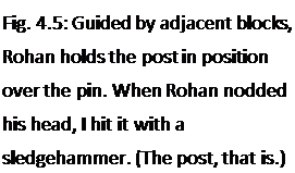 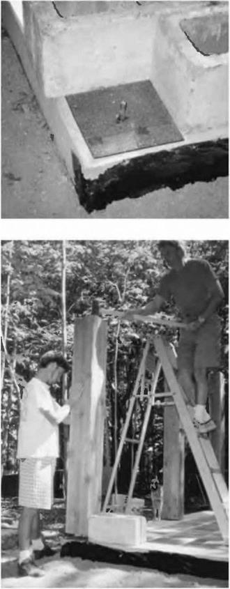  Erecting an individual post is a two-person, two-step process, because of the positioning pin. First, the post is stood up onto the pin. Concrete blocks can be used as positioning aids so that you know that the post will stand on just the right footprints, as seen in Figs. 4.4 and 4.5. Make sure that the post is the right length and has two good squared ends. Now, while one person holds the post, the other person, on a stepladder, gives it one stiff “thwack” with a heavy hammer, making an imprint on the underside of the post. Next, the post is taken down and a hole of the same diameter as the threaded lag screw is drilled at least as deep as the pin is high, say two inches in our example. Finally, the post is stood up again, but this time it is there to stay, the pin in the hole keeping it in the right place, even during an earthquake. Erecting an individual post is a two-person, two-step process, because of the positioning pin. First, the post is stood up onto the pin. Concrete blocks can be used as positioning aids so that you know that the post will stand on just the right footprints, as seen in Figs. 4.4 and 4.5. Make sure that the post is the right length and has two good squared ends. Now, while one person holds the post, the other person, on a stepladder, gives it one stiff “thwack” with a heavy hammer, making an imprint on the underside of the post. Next, the post is taken down and a hole of the same diameter as the threaded lag screw is drilled at least as deep as the pin is high, say two inches in our example. Finally, the post is stood up again, but this time it is there to stay, the pin in the hole keeping it in the right place, even during an earthquake.
By the one-post-at-a-time method, each post must be supported in two different directions by long diagonal scrap timbers, nailed to wooden stakes pounded firmly into the ground. (If the post is in the middle of a slab, or at some intermediate point along the wall, horizontal pieces of flat scrap, such as two-foot long (61 centimeter) pieces of two-by-four, can be screwed to the bottom of the post to act as stabilizers. A piece of plywood in the shape of an isosceles triangle will work nicely, too. Review figure 2.21).
Posted by admin on 19/ 11/ 15
Covering the wood house frame with house – wrap, a thin protective layer, is the next step before finish siding is applied. You can use the old, reliable housewrap—rolls of 30-lb. felt paper, or you can try one of the modern housewraps, such as Tyvek®, Barricade®, and Typar®. These are lightweight, fabric-like materials that come in rolls and are literally wrapped around the walls of a house. The main purpose of this treatment is to form a drainage plane behind the siding to stop wind-driven water from penetrating into the wall cavity. No siding is completely watertight, so in areas where hard, wind-driven rain is common, housewrap can help protect the walls from moisture damage. However, house – wrap is not a replacement for good flashing around doors, windows, and decks. Rather, it adds to those flashing systems, with upper layers
2 x scaffolding planks need to be strong
and safe to use. Try reinforcing these boards by drilling a %-in. hole through the plank edge about 8 in. from each end. Insert and tighten a %-in. bolt with a washer on each end through the holes. This will help keep the plank from splitting.
 always overlapping lower layers like shingles on a house. In addition to helping keep water out, housewrap reduces air leakage but is porous enough to allow water vapor to escape from inside the house. always overlapping lower layers like shingles on a house. In addition to helping keep water out, housewrap reduces air leakage but is porous enough to allow water vapor to escape from inside the house.
Climate plays a huge role in determining how housewraps are used. We live in a country with an astonishing diversity of climates, and these varied conditions require different solutions for protecting a house and its inhabitants from the elements. Even the type of wall covering you use can affect your wrapping strategy. Talk to builders in your area (and to the building inspector) to find out what’s used locally and why.
Installing housewrap
Housewrap may be attached directly to studs, on top of wall sheathing, or over rigid foam. Modern plastic housewrap is usually white or gray and comes in different widths and lengths. Don’t plan to install housewrap on your own; this is definitely a two – or three – person job. The only installation tools required
are a staple gun and a sharp utility knife. Here are the basic steps:
1. Cover the inside and outside corners. This is an optional step, but one that I routinely take to provide extra protection in these critical areas, especially if the siding will be installed directly over the studs. Fold a 2-ft.-wide wall-high length of wrap in half and staple
it vertically over the outside corners and into the inside corners.
2. Wrap the house from corner to corner. A 9-ft.-high roll usually fits just right on houses with 8-ft. studs. Staple the free end of the roll near a corner of the house and unroll it over the entire side of the house, with one
or two helpers stapling as you go. Cover the window and door openings. When you’ve finished one side, simply keep rolling onto the next one until you’ve made your way all around the house.
3. Seal joints and repair tears, if necessary. Hopefully, you can skip this step. But if you can’t create a continuous wrap around the house, make sure you overlap the wrap by at least 16 in. or one stud space. Seal the seam with the sticky, self-adhering tape made for this purpose. Be sure to get some when you pick up (or take delivery of) your housewrap. Repair a tear in the housewrap by applying a patch from the top of the wall down over the tear, so that water will drain properly. Seal the tear with tape.
4. Cut and wrap the window and door openings. To finish the installation, cut an “X”-slice in the housewrap over each window and door opening, then pull the cut ends inside the house and staple them around the trimmers, header, and rough sill. Staple the flaps right away so they don’t get caught by the wind and torn.
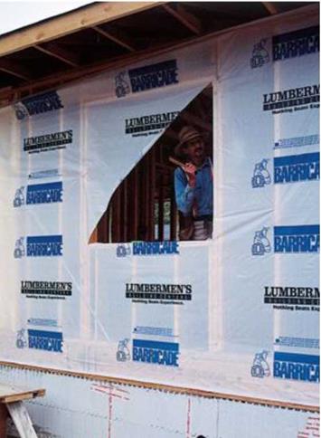
  Housewrap helps to keep wind and water out. Modern housewraps can be applied over sheathing or directly over framing, as was done here. After wrapping the walls completely, make “X” cuts at the window and door openings, then fold and staple the flaps inside. [Photo © Memo Jasso] Housewrap helps to keep wind and water out. Modern housewraps can be applied over sheathing or directly over framing, as was done here. After wrapping the walls completely, make “X” cuts at the window and door openings, then fold and staple the flaps inside. [Photo © Memo Jasso]
    Simple flashing details Simple flashing details
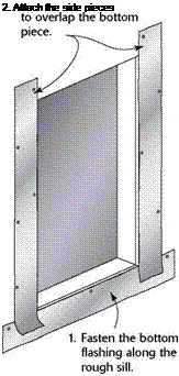
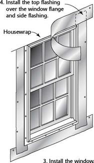
Whether or not you wrap the house, it’s important to flash around the window and door openings. Especially with windows, proper flashing can prevent the water that runs down both sides of the window from entering the wall cavity through the sill area. To flash window and door openings, I generally use 6-in.- to 8-in.-wide strips of felt paper, installing the strips as shown in the illustration below. Don’t forget to install the top piece of flashing after the window has been set in its opening. If housewrap is used, you can still install a top piece of flashing. Cut a horizontal slit in the housewrap above the window, then slip the top edge of the top flashing piece into the slit.
Posted by admin on 19/ 11/ 15
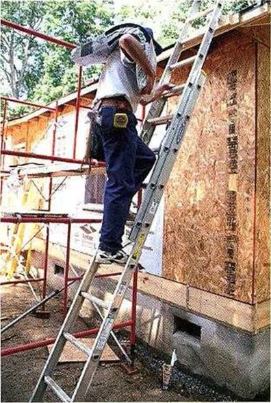
HERE IN THE WEST, we try to order shingles the day before they will be installed. Suppliers arrive with a hoist and stack both shingles and felt paper directly onto the roof. An experienced celivery person knows to stack bundles of shingles about 6 ft. apart on both sides of the roof.
The other way to get shingles onto the roof is the hard way—hoisting one bundle at a time. If you must haul roofing shingles up to the roof yourself, make sure you have a secure ladder that is positioned properly and is 2 ft. to 3 ft taller than the roof. It’s a good idea to nail a temporary 2x tread at the spot on the roof where you will step off the ladder. This tread provides a solid foothold where you need it most.
Bust the bundle. Shingles are much easier to carry if you "bust" the bundle first. Pick up a bundle and lay it across a sawhorse. Push down on both
ends until the bundle curves downward. A curved bundle is easier and safer to carry on your shoulder than a straight, stiff one (see the photo at left).
Pick up the bundle by bending your knees and draping the bundle over your shoulder. This is not always easy, because a bundle of shingles can weigh as much as 80 lb. Ascend the ladder slowly and watch your balance. Don’t throw down bundles between rafters, or you could break the OSB sheathing. Just set them on the roof without a lot of force, and space the bundles so that they’re easy to grab while you’re shingling.
STARTER COURSE, SECOND LAYER. This shingle layer, and every subsequent course, is installed right side up (tabs down). Position the first shingle of this top layer flush with the lower edge of the bottom layer, with one of its short edges on the second vertical offset line.
It doesn’t make any difference whether vou go to the right or the left of the second vertical line—all that matters is that the tabs of this top layer are offset from the tabs of the bottom layer by 6 in. Nail each and every shingle the same way. Use four /-in. roofing nails and drive one nail about 1 in. from each edge and one nail above each slot. Drive all nails just below the tar strip and above the cutout.
REMAINING COURSES. Start several courses of shingles, offsetting each by 6 in. This allows other shinglers to work in both directions. Hold each new course of shingles to the 5-in. horizontal mark above the last course, alternating shingle ends on the vertical marks. This establishes a pattern with a 6-in. offset on each shingle.
At vent pipes, install a roof jack, or metal flashing, over the vent to keep out water. Install shingles below the pipes centerline beneath the flashing. Install those above the centerline on top of the flashing (see the top photo on the facing page). The flashing can be nailed near the top corners of the tin, before
 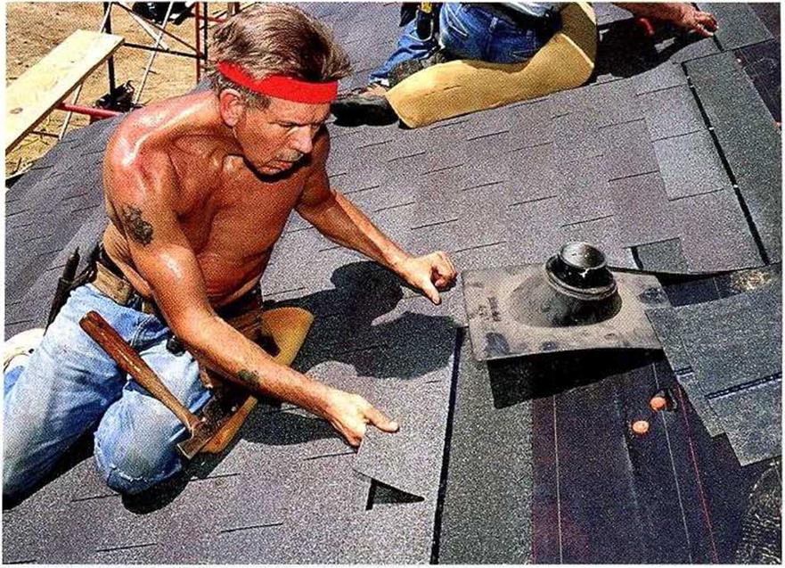  shingles are laid on top of it. Don’t nail the bottom corners down, though, as this could cause the flashing to leak. shingles are laid on top of it. Don’t nail the bottom corners down, though, as this could cause the flashing to leak.
At the gable ends, cut the shingles to length before nailing them in position. Mark the length and cut them from the back with a utility knife. Rather than carrying a square, 1 use another shingle as a straightedge to guide the cut and a third shingle as a protective base below the cut. At the top, cut the shingles flush with the sheathing that was cut back to accommodate the ridge vent.
Posted by admin on 19/ 11/ 15
The Roman Nemausus (Nimes) is much older than Lyon, founded in the 6th century BC, even before the conquest of Gaul by the Romans. Nimes was the capital of the Arecomic Volques, a Gallic people often allied with the Romans. Nimes is naturally well supplied with water, from wells and especially from the Fontaine spring, abundant and perennial. Under Augustus the spring was the subject of major construction, including a masonry canal and basin at its outlet. The need for an aqueduct only came later under the pressure of urban development (20,000 inhabitants in the Gallo-Roman Nemausus), with the objective of supplying water to the highest areas of the city above the level of the Fontaine (at an elevation of 51.1 m). Under Claudius, in the middle of the 1st century AD,[243] the Eure fountain spring is tapped near Uzes at an altitude of 72 m.[244]
![The Nimes Aqueduct and the Pont du Gard[242] Подпись: Figure 6.15 The Pont du Gard, supporting the aqueduct of NTmes across the Gardon (photo by the author).](/img/1312/image097_4.gif) |
![The Nimes Aqueduct and the Pont du Gard[242] The Nimes Aqueduct and the Pont du Gard[242]](/img/1312/image098_5.jpg) |
Although it is only some 20 km from the source to Nimes as the crow flies, the aqueduct had to wind around the vast scrubland plateau of Nimes, whose elevation is above 100 m (see Figure 6.14). There are numerous obstacles to be crossed on this plateau. These obstacles include ravines that are dry in summer but subject to violent floods, such as the Bornegre ravine with its three-arch bridge; passes, with the two-level arched bridge of Font-Menestiere; and notably the sunken valley of the Gardon, across which the highest bridge-aqueduct of the Roman Empire is built, the Pont du Gard (Figure 6.15). The bridge is about 360 m long, and carries the canal of the aqueduct at an altitude of 65 m, some 48.4 m above the bed of the river. Just upstream of the bridge the canal has a basin provided with a gate and a discharge canal enabling diversion of the discharge of the aqueduct (or its excess) into the Gardon, if necessary. Downstream of the bridge, the canal traverses the rough terrain along the edge of the limestone plateau by means of multiple switchbacks, crossing ravines on small bridges. The canal passes through three tunnels of about 400 m in length, further downstream near Sernhac, then again near 39
![The Nimes Aqueduct and the Pont du Gard[242] The Nimes Aqueduct and the Pont du Gard[242]](/img/1312/image099_5.jpg) Nimes. The terminal point of the aqueduct is the water tower in the city (castellum), at an elevation of 58.95 m. Nimes. The terminal point of the aqueduct is the water tower in the city (castellum), at an elevation of 58.95 m.
All of these bridges are designed to handle the strong floods typical of the Mediterranean climatic regime. The bases of the bridge piers are protected by shaped prows on the upstream face. The bridges all leave a very large opening for flood passage; the widths of the openings of the arches of the Pont du Gard are 24.5 m and 19 m.
The castellum of Nimes (Figure 6.17) is one of the rare Roman water towers still conserved in more or less its original state. The aqueduct dumps water into the tower’s
|
![The Nimes Aqueduct and the Pont du Gard[242] The Nimes Aqueduct and the Pont du Gard[242]](/img/1312/image100_2.jpg)
Figure 6.16 Longitudinal profile of the Nimes aqueduct, from the data of Fiches (1991).
|
Figure 6.17 The castellum of Nimes: this distribution basin is the terminal point of the Nimes aqueduct. It is visible in the city, on rue de la Lampeze (photo by the author).
circular basin of 5.5 m inside diameter and depth 1.4 m. Issuing from the basin are ten circular distribution pipelines of 0.4 m diameter. Valves enable the isolation of one circuit or another, and drains in the bottom make it possible to empty the basin.
The aqueduct has several slope changes;[245] upstream of the Pont du Gard it is only 38 cm/km on the average, which is relatively small compared to other aqueducts. But downstream of the bridge, the slope is only 8 cm/km along a particularly sinuous segment of more than 10 kilometers length. The theoretical maximum discharge for this slope can be estimated at around 40,000 m3/day. Even though this aqueduct may not attract the same admiration as the Pont du Gard, it is all the more impressive for its incredibly small slope, and the precision of surveying and construction that this implies.
These slope changes have hydraulic consequences that were not well understood or mastered by the Roman engineers. In a canal of constant width, the depth of water is larger when the slope is small; yet the Nimes aqueduct was initially constructed for an essentially constant depth. Early on, it became necessary to raise the canal walls in several locations (of flatter slope) to avoid overflow.
Another problem is the fact that the water from the Eure fountain is very calcareous. Over the years, the useful cross-section of the aqueduct’s canal becomes considerably reduced by deposits, effectively reducing the discharge to a value that was probably only about 20,000 m3/day. The canal had to be scoured out on several occasions.
| |


 A window’s U-factor is the inverse of its R-value; the lower the U-factor, the better the window is at resisting heat flow. A low U-factor is desirable in all climates. While the best double-glazed windows have a U-factor of about 0.27, triple-glazed windows have U-factors as low as 0.17.
 The Portland demonstration subdivision was arranged in clusters of four detached units. The city allowed one 1 1/2-inch PVC water line to run from the main to each cluster and 3/4-inch PVC from there to each unit. This was instead of one 1-inch line from the main to each unit. Cost savings amounted to $32 per unit.


 Erecting an individual post is a two-person, two-step process, because of the positioning pin. First, the post is stood up onto the pin. Concrete blocks can be used as positioning aids so that you know that the post will stand on just the right footprints, as seen in Figs. 4.4 and 4.5. Make sure that the post is the right length and has two good squared ends. Now, while one person holds the post, the other person, on a stepladder, gives it one stiff “thwack” with a heavy hammer, making an imprint on the underside of the post. Next, the post is taken down and a hole of the same diameter as the threaded lag screw is drilled at least as deep as the pin is high, say two inches in our example. Finally, the post is stood up again, but this time it is there to stay, the pin in the hole keeping it in the right place, even during an earthquake.
 always overlapping lower layers like shingles on a house. In addition to helping keep water out, housewrap reduces air leakage but is porous enough to allow water vapor to escape from inside the house.
 Housewrap helps to keep wind and water out. Modern housewraps can be applied over sheathing or directly over framing, as was done here. After wrapping the walls completely, make “X” cuts at the window and door openings, then fold and staple the flaps inside. [Photo © Memo Jasso]



 shingles are laid on top of it. Don’t nail the bottom corners down, though, as this could cause the flashing to leak.
![The Nimes Aqueduct and the Pont du Gard[242] Подпись: Figure 6.14 The Roman aqueduct of Nimes (after Fabre, Fiches, Leveau, Paillet, 1992).](/img/1312/image095_7.gif)
![The Nimes Aqueduct and the Pont du Gard[242] The Nimes Aqueduct and the Pont du Gard[242]](/img/1312/image096_2.jpg)
![The Nimes Aqueduct and the Pont du Gard[242] Подпись: Figure 6.15 The Pont du Gard, supporting the aqueduct of NTmes across the Gardon (photo by the author).](/img/1312/image097_4.gif)
![The Nimes Aqueduct and the Pont du Gard[242] The Nimes Aqueduct and the Pont du Gard[242]](/img/1312/image098_5.jpg)
![The Nimes Aqueduct and the Pont du Gard[242] The Nimes Aqueduct and the Pont du Gard[242]](/img/1312/image099_5.jpg) Nimes. The terminal point of the aqueduct is the water tower in the city (castellum), at an elevation of 58.95 m.
Nimes. The terminal point of the aqueduct is the water tower in the city (castellum), at an elevation of 58.95 m.![The Nimes Aqueduct and the Pont du Gard[242] The Nimes Aqueduct and the Pont du Gard[242]](/img/1312/image100_2.jpg)