Number of roller passes

Usually six to nine roller passes are enough to compact an SMA mixture. Moreover, compaction should not cause squeezing of the mastic onto the surface. The number of passes with vibrations should be limited to the indispensable minimum (most frequently, three).

On many construction sites or at the start of a new SMA mixture, it is recom­mended that the effectiveness of rolling in relation to the number of passes and type of rollers be tested on a specified section. The increase in density with more rolling passes is monitored with, for example, a nuclear density gauge, and the number of passes to reach the desired density is determined.

Gypsum Board

Gypsum board, also known as gypboard, Sheetrock, or drywall, is the most common form of interior wall sheathing in modern res­idential construction. It is considerably less expensive than plaster. The 4- by 8-foot sheets are attached to the studs, then taped, sealed, textured, and painted.

Gypsum board is composed of natural gyp­

sum sandwiched between two sheets of card­board made from recycled newsprint. This cardboard backing creates problems when water damage occurs because it is a nutrient that encourages mold growth. In his mold in­vestigation work, John Banta has seen many cases where mold has begun to grow less than 72 hours after water damage occurs. Getting immediate help from a remediation specialist with the proper drying equipment is often the key to saving money and health when a water disaster occurs. A skilled specialist will know how to safely remove mold while isolating it so that no further contamination occurs.

Gypsum Board Installation

The installation of gypsum board in standard practice may negatively affect indoor air qual­ity for the following reasons:

• Dust and debris within wall cavities are often enclosed and concealed by the gyp – board. If dust and debris are not cleaned
out, they can cause problems over time. Dust can eventually work its way back into the living space and become a main­tenance problem as well as an air pollutant, and other construction debris can become a breeding ground for mold if it becomes wet.

• Gypsum board itself will outgas because of the inks remaining in the recycled news­paper. To seal in the small quantity of un­desirable VOCs generated by the surfacing board, the walls may be primed with a spe­cialty paint or primer. With the printing industry shift to soy-based ink, outgassing may become less of a problem.

• The standard premixed joint compounds may contain several undesirable chemi­cals, including formaldehyde.

• Like plaster, gypsum board is highly ab­sorbent. In standard practice, gas and ker­osene heaters may be used to dry the joint compounds. The byproducts of combus­tion are absorbed into the walls and will outgas into the building envelope of the completed home.

• Special gypsum boards are made for use in areas that get wet, such as showers, tub surrounds, and countertops. When walls using these products in wet areas are dis­assembled after several years, the water re­sistant papers are often moldy, especially at the joints between boards. Cementitious boards without paper backing are made to be used as backerboard in wet locations and do not have the same mold problems that are associated with the paper-backed products.

To avoid these problems, include the follow­ing specifications:

• All wall cavities shall be thoroughly vacu­umed and free of debris prior to installa­tion of the gypsum board.

• Joint compound shall be a powdered joint cement and texture compound such as Murco M-ioo HiPo or approved equal that is formulated with inert fillers and without formaldehyde or preservatives.

• Heaters fueled by gasoline or kerosene are prohibited.

• If relative humidity rises above 55 percent, electric dehumidification shall be applied until relative humidity remains consis­tently between 45 and 55 percent without additional dehumidification. Interior sur­face temperatures shall remain above 50 degrees.

• The joint compound must be completely dry before primer is applied.

• In wet areas such as showers, tub sur­rounds, and sink counters, cementitous backerboard without paper backing shall be used. Durock, Hardibacker Board, Permabase, or approved equal maybe used for this purpose.

Creating an Air Barrier with Gypsum Board

In 2X frame wall construction there are often undesirable emissions from materials used in the building envelope. Since, even with the greatest care in choosing materials, there may not be completely inert, cost-effective prod­ucts available, it often makes sense to create an airtight barrier on the inside face of the building envelope to block the entry of unde­sirable substances from within the wall cavity itself or from adjoining environments. This also makes great sense from the standpoint of moisture control and energy efficiency. A tightly sealed and taped gypsum board wall, in combination with gasketed or foamed sill and top plates and thorough sealing around all openings (windows, electrical outlets, plumb­ing penetrations, and recessed lighting), will create an airtight barrier that can perform the same function as an air barrier made of care­fully joined plastic sheeting as described in the section on air barriers in Division 7.

This type of airtight assembly will pre­vent airborne moisture from pouring through cracks into the wall but will allow a small amount of moisture to be carried through by diffusion. In climatic conditions where the building would tend to dry to the inside (i. e., when the inside temperature of the building is cooler than the outside temperature), the gypsum board assembly will also allow mod­erate amounts of moisture in the wall cavity to dry out instead of remaining trapped. Be­cause gypsum board allows some water vapor to move through it, this is a superior solu­tion for blocking chemical gases out of living spaces. This is especially relevant where air conditioning is used and moisture would tend to condense on a layer of impermeable plas­tic sheeting (if one were present) and remain trapped in the wall cavity.

Gypsum board can store limited amounts of moisture before it begins to mold. It will not stand up to large amounts of wetting. In hot, humid climates there must be a sufficient vapor barrier on the exterior of the building to prevent excessive moisture from penetrating the wall from the outside and causing the card­board on the gypsum board to mold. Similarly, in heating conditions it may be necessary to use a paint or primer with a low permeability rating to retard some of the water vapor that would naturally diffuse through the gypsum board. 86001 Seal is a primer that has a low enough rating to serve as a vapor retardant.

Gypsum board can be purchased with foil backing. Although foil is an excellent vapor blocker, we do not recommend it because it is problematic if water damage occurs. As­sessment is hampered because the foil pre­vents a moisture meter from taking accurate readings. It is also more difficult to dry out a flooded wall cavity when foil-backed gypsum board has been used.

To summarize, using gypsum board in an airtight manner on stud frame construction makes sense in all climatic conditions. How­ever, this is only one part of the moisture con­trol strategy. Developing an overall strategy for the control of moisture in any building must take into account the climatic conditions of the site. The best solution will be different for different locations. While a full discussion of moisture movement and best solutions is beyond the scope of this book, an understand­ing of moisture movement is essential for the ongoing success of a health-enhancing build­ing in all but the most forgiving dry climates. To this end, we highly recommend the Build­ers Guides by Joseph Lstiburek, listed at the end of Division 7.

Determinations of Availability and Unavailability

5.4.1 Terminology

A repairable system experiences a repetition of the repair-to-failure and failure – to-repair processes during its service life. Hence the probability that a system is in an operating condition at any given time t for a repairable system is different from that for a nonrepairable system. The term availability A(t) generally is
used for repairable systems to indicate the probability that the system is in an operating condition at any given time t. It also can be interpreted as the percentage of time that the system is in an operating condition within a specified time period. On the other hand, reliability ps(t) is appropriate for nonrepairable systems, indicating the probability that the system has been continuously in an operating state starting from time zero up to time t.

There are three types of availability (Kraus, 1988). Inherent availability is the probability of a system, when used under stated conditions and without consideration of any scheduled or preventive actions, in an ideal support en­vironment, operating satisfactorily at a given time. It does not include ready time, preventive downtime, logistic time, and administrative time. Achieved availability considers preventive and corrective downtime and maintenance time. However, it does not include logistic time and administrative time. Oper­ational availability considers the actual operating environment. In general, the inherent availability is higher than the achieved availability, followed by the operational availability (see Example 5.13). Of interest to design is the inherent availability; this is the type of availability discussed in this chapter.

In general, the availability and reliability of a system satisfy the following inequality relationship:

0 < ps(t) < A(t) < 1 (5.40)

with the equality for ps(t) and A(t) holding for nonrepairable systems. The reli­ability of a system decreases monotonically to zero as the system ages, whereas the availability of a repairable system decreases but converges to a positive probability (Fig. 5.16).

Determinations of Availability and Unavailability

Figure 5.16 Comparison of reliability and availability.

The complement to the availability is the unavailability U(t), which is the probability that a system is in a failed condition at time t, given that it was in an operating condition at time zero. In other words, unavailability is the percent­age of time the system is not available for the intended service in time period (0, t], given that it was operational at time zero. Availability, unavailability, and unreliability satisfy the following relationships:

A(t) + U (t) = 1 (5.41)

0 < U(t) < pf (t) < 1 (5.42)

For a nonrepairable system, the unavailability is equal to the unreliability, that

is, U(t) = pf (t).

Recall the failure rate in Sec. 5.2.2 as being the probability that a system experiences a failure per unit time at time t, given that the system was oper­ational at time zero and has been in operation continuously up to time t. This notion is appropriate for nonrepairable systems. For a repairable system, the term conditional failure intensity p(t) is used, which is defined as the proba­bility that the system will fail per unit time at time t, given that the system was operational at time zero and also was in an operational state at time t. Therefore, the quantity p(t) dt is the probability that the system fails during the time interval (t, t + dt], given that the system was as good as new at time zero and was in an operating condition at time t. Both p(t) dt and h(t) dt are probabilities that the system fails during the time interval (t, t + dt], being conditional on the fact that the system was operational at time zero. The dif­ference is that the latter, h(t) dt, requires that the system has been in a con­tinuously operating state from time zero to time t, whereas the former allows possible failures before time t, and the system is repaired to the operating state at time t. Hence p(t) = h(t) for the general case, and they are equal for nonre­pairable systems or when h(t) is a constant (Henley and Kumamoto, 1981).

A related term is the unconditional failure intensity w(t), which is defined as the probability that a system will fail per unit time at time t, given that the system is in an operating condition at time zero. Note that the unconditional failure intensity does not require that the system is operational at time t. For a nonrepairable system, the unconditional failure intensity is equal to the fail­ure density ft (t). The number of failures experienced by the system within a specified time interval [t1, t2] can be evaluated as

W(tb t2) =f 2 w(t) dr (5.43)

t1

Hence, for a nonrepairable system, W(0, t) is equal to the unreliability, which approaches unity as t increases. However, for repairable systems, W(0, t) would diverge to infinite as t gets larger (Fig. 5.17).

On the repair aspect of the system, there are elements similar to those of the failure aspect. The conditional repair intensity p(t) is defined as the probability that a system is repaired per unit time at time t, given that the system was in

Determinations of Availability and Unavailability

Figure 5.17 Expected number of failures for repairable and nonrepairable systems.

an operational state initially at time zero but in a failed condition at time t. The unconditional repair intensity y(t) is the probability that a failed system will be repaired per unit time at time t, given that it was initially in an operating condition at time zero. The number of repairs over a specified time period (ti, t2), analogous to Eq. (5.43), can be expressed as

r(ti, t2) = [ y(r)dr (5.44)

Jt1

in which Г(0, t) is the expected number of repairs for a repairable system within the time interval [t1, t2]. A repairable system has Г(0, t) approaching infinity as t increases, whereas it is equal to zero for a nonrepairable system. It will be shown in the next subsection that the difference between W(0, t) and Г(0, t) is the unavailability U(t).

Materials MORE SIDING OPTIONS

IN ADDITION TO VINYL SIDING, there are three more exterior finisies to consider if you’re inter­ested in affordability, low maintenance, and attrac­tive appearance:

Composite wood. These planks are made the same way as OSB sheathing panels, but they look like solid-wood clapboards or horizontal lap siding when installed. This siding comes with a factory-applied primer coat, and it needs to be painted after instal­lation. Composite-wood planks don’t split, crack, or warp like solid-wood siding does, but they may not be a wise choice in extremely wet climates.

Stucco. Two tyaes of stucco finishes can be applied to house exteriors. Lightweight acrylic-type stucco treatments are available for application over specially prepared foam insulation board. And old – fashioned Portland cement-based stucco can be applied to masonry walls and to wire lath that’s been fastened to wall sheathing or directly to studs. It’s best to hire experienced professional crews to do these treatments. In hot, sunny cli­
mates, stucco stands up better than most other sid­ing treatments.

Tl-11. This plywood paneling can serve as both sheathing and finish siding, so it can be a real money saver. Tl-11 typically comes in 4×8 sheets and is available in different thicknesses. The "good" side of the panel has a rough-sawn wood finish that is divided lengthwise by a series of parallel grooves. A house sided with Tl-11 has a rustic appearance.

The panels are installed just like regular sheath­ing is—эу nailing through the plywood into the studs and plates. Be sure to use galvanized nails. The long edge of each panel is milled to meet in a lap joint. Tl-11 needs the protection of a good exterior paint or stain for the sake of appearance and longevity. Although it’s not a good long-term (20 years or more) siding, it enables you to cut down on construction costs and provides a workable base for subsequent siding treatments. Vinyl siding, fiber-cement siding, clapboards, and shingles can all be applied right over Tl-11.

Подпись: Helping HandПодпись: Be careful with delicate sheathing. Take aim carefully when installing foam sheathing. A misdirected hammer blow can easily dent or puncture the foam. Install these insulating panels with broad-head roofing nails or plastic-cap nails. Space the nails about 16 in. apart along the edges and 24 in. apart everywhere else.

range from T in. to 8 in.; there’s even a wide» single-board siding panel with a decorative bead along the bottom edge. Manufacturers offer most of their siding with either a smooth surface or a textured, wood-grain finish.

When choosing a siding color, hear in mind that it will fade slightly over time. Also, darker siding will absorb more heat and expand more than light-colored vinyl.

To estimate how much siding vou’ll need, refer to the sidebar on p. 150. Keep in mind that when vou buy vinvl siding, vou’re act nail v buying a comprehensive system of siding components: siding panels, J-channel, inside

and outside corner pieces, and other types of trim designed to simplify the installation and enhance the appearance. Siding manufacturers also make compatible vinyl soffit paneling and other components, such as vents, electrical outlet covers, and special exterior trim. It’s smart to get an overview of the full range of compatible products before you order siding. Go online to visit manufacturers Web sites or call to request product information (see Resources on p. 278).

Water Influence on Bearing Capacity

and Pavement Performance: Field Observations

Robert Charlier[20], Pierre Hornych, Mate Srsen, Ake Hermansson, Gunnar Bjarnason, SigurSur Erlingsson and Primoz Pavsic

Abstract This chapter presents a mechanical behaviour study, i. e. the bearing capacity as a function of the moisture degree. The field point of view is expressed and the chapter summarises a number of observations on road behaviour, in relation to variations of moisture. First, the road structure is recalled with respect to the mechanical analysis point of view. Then some observations onfield under temperate climate, humid, are given. In a second step, the specific case of frost and thawing are discussed.

Keywords Bearing capacity ■ moisture level ■ field measurement ■ stiffness ■ rutting ■ thawing

8.1 Introduction

This chapter introduces the study of mechanical behaviour, i. e. it seeks to describe bearing capacity as a function of the moisture degree. This description is based on a summary of road behaviour with respect to variations of water content as observed in-situ.

Initially, the road structure is presented from the point of view of a mechanical analysis. The mechanical and hydraulic specific behaviour of each subgrade layer is discussed. Next, the chapter briefly analyses water penetration and the water effect on the road structure layers before illustrating the water-induced mechanical effects. The change of water content over time is shown for specific locations that are sub­jected to a humid, temperate, climate. Then a consideration of the development of ruts, i. e. the strains and deformation, with time is given. A discussion of the stiffness of a road structure is also given as it relates to the moisture level. A clear decrease of the stiffness and an increase of the strain accumulation are observed when the moisture increases.

In the second part of the chapter, specific cases of frost and thawing action are discussed. In particular, the stiffness decrease during and after thawing is described. Field measurements of temperature, of layer moisture and of deflectometer stiffness are presented.

WAREHOUSES, FOUNDRIES, AND SUCH

Warehouses, foundries, manufacturing buildings, and similar buildings have some special requirements. For example, a shower must be provided for each 15 people who may be exposed to excessive heat or to skin contamination with poisonous, infectious, or irritating material. When you look at the table in Figure 9.12 you will see a number of numbers at the topic headings. Refer back to Figure 9.2 for an understanding of the special notes. An example of such a note is number 14 in the list of Figure 9.2. It says that one lavatory must be supplied for every 15 people who may have exposure to skin contamina­tion with poisonous, infectious, or irritating materials. Refer all of the special notes before you begin figuring your fixture needs.

LIGHT MANUFACTURING

Buildings used for light manufacturing are affected by the special notes listed in Figure 9.2. Pay attention to all the note references in the table labeled as Figure 9.13. You will see that the sizing table is like the others that we have been using and is just as easy to negotiate.

CHARACTERISTICS OF ROADSIDE BARRIERS

Depending on their deflection characteristics upon impact, roadside barriers can be classified as flexible, semirigid, or rigid. Table 6.2 lists the most widely used barriers in each classification. Details of most of these operational barriers are presented along with other available information in Figs. 6.13 through 6.22. The dynamic deflection listed is that observed during the standard test defined by NCHRP Report 350 for the test levels listed in Table 6.2 as defined in Art. 6.4. Other characteristics of the barriers are discussed below.

TABLE 6.1 Barrier Warrants for Nontraversable Terrain and Roadside Obstacles*f

Подпись: Bridge piers, abutments, and railing ends Boulders Culverts, pipes, headwalls Cut and fill slopes (smooth) Cut and fill slopes (rough) Ditches (parallel) Ditches (transverse) Embankment Retaining walls Sign and luminaire supports^ Traffic signal supports§ Trees Utility poles Permanent bodies of water Shielding generally required A judgment decision based on nature of fixed object and likelihood of impact A judgment decision based on size, shape, and location of obstacle Shielding not generally required A judgment decision based on likelihood of impact
Refer to Figs. 6.5 and 6.6 Shielding generally required if likelihood of head-on impact is high A judgment decision based on fill height and slope (see Fig. 6.12)

A judgment decision based on relative smoothness of wall and anticipated maximum angle of impact

Shielding generally required for nonbreakaway supports

Isolated traffic signals within clear zone on

high-speed rural facilities may warrant shielding A judgment decision based on site-specific circumstances

Shielding may be warranted on a case-by-case basis

A judgment decision based on location and depth of water and likelihood of encroachment

*Shielding nontranversable terrain or a roadside obstacle is usually warranted only when it is within the clear zone and cannot practically or economically be removed, relocated, or made breakaway and it is deter­mined that the barrier provides a safety improvement over the unshielded condition.

fMarginal situations, with respect to placement or omission of a barrier, will usually be decided by acci­dent experience, either at the site or at a comparable site.

$Where feasible, all sign and luminaire supports should be a breakaway design regardless of their distance from the roadway if there is reasonable likelihood of their being hit by an errant motorist. The placement and locations for breakaway supports should also consider the safety of pedestrians from potential debris resulting from impacted systems.

§In practice, relatively few traffic signal supports, including flashing light signals and gates used at railroad crossings, are shielded. If shielding is deemed necessary, however, crash cushions are sometimes used in lieu of a longitudinal barrier installation.

Source: From Roadside Design Guide, AASHTO, Washington, D. C., 2002 and 2006, with permission.

HAIR SHOPS

Hair shops, like beauty salons and barber shops are required to have a drink­ing fountain and a service or utility sink. Figure 9.11 shows the basic require­ments for fixtures in these types of buildings. it is worth noting that only one lavatory is required for each bathroom, regardless of the occupancy load. it is also possible that beauty shops and barber shops might be required to main­tain only one restroom for occupants.

”I

oo


Подпись: PLUMBER’S AND PIPE FITTER’S CALCULATIONS MANUAL

Building or occupancy2

Occupant content2

Water closets3

Lavatories4

Bathtubs, showers and miscellaneous fixtures

Clubs, lounges, and

40 sq ft per

Persons (total)

Male

Female

Persons (total)

Male

Female

Comply with board of

restaurants with club

person

1-50

2

2

1-150

1

1

health requirements

or lounge6

51-100

3

3

151-200

2

2

101-300

4

4

201-400

3

3

For each

For each

additional 200

additional 200

persons over

persons over

300, add

1

2

400, add

1

1


FIGURE 9.9 ■ Minimum fixtures for clubs and lounges. (Courtesy of Standard Plumbing Code)

Do-it-yourself

50 sq ft

Persons

Persons

One drinking fountain and

laundries6

per person

(total)

Male

Female

(total)

Male

Female

one service sink.

1-50

1

1

1-100

1

1

51-100

1

2

101-200

2

2

Подпись: CALCULATING MINIMUM PLUMBING FACILITIES ■ 179

FIGURE 9.10 ■ Minimum fixtures for do-it-yourself laundries. (Courtesy of Standard Plumbing Code)

00

о


Подпись: PLUMBER'S AND PIPE FITTER'S CALCULATIONS MANUAL

Beauty shops

One drinking fountain and

and

50 sq ft

Persons

Persons

one service or other

barber shops6

per person

(total)

Male

Female

(total)

Male

Female

utility sink.

1-35

1

1

1-75

1

і

36-75

2

2


FIGURE 9.11 ■ Minimum fixtures for hair-care establishments. (Courtesy of Standard Plumbing Code)

Some More About Doorframes and Posts

With a lot of natural building being done these days, cordwood, cob, or straw bale walls of 16 to 24 inches thick are not uncommon. Doorframes will have to be equally wide. Earth woods cordwood walls are all 16 inches (40.6 centimeters) thick, so I make my doorframes from two four-by-eight timbers, with their 4-inch
(ioi millimeter) dimensions butted together, forming, effectively, a 4-by-i6-inch door post. These vertical timbers can be fastened together with metal straps, as shown in Fig. 4.54.

Fastening such a doorframe to a concrete floor requires two pins, one for each of the four-by-eights, to stop the doorframe from rotating. Alternatively, a 12- to 16-inch-long piece of angle iron can fasten the frame to the floor as discussed above, and the angle iron is hidden from view in the cordwood wall.

With single posts, such as eight-by-eights, two pins instead of one will stop the post from rotating, and I have mentioned this to students for years. In point of fact, we only used one pin for each of the posts at both Log End Cave and Earthwood, and I have seen no sign of any post rotating. The heavy concentrated load on these posts imparts tremendous friction at each post end, and rotation would be highly unlikely, especially after girders and floors above the posts tie everything together. One pin is enough with heavy structures.

Chris Ryan, like any good builder, likes to use patterns to make jobs easier. My son Rohan helped him set up a corner post at his garage while I took the following sequence of photos:

Fig. 4.8: Chris made a pattern from an eight inch piece of two-by-eight, held it firmly on the corner of his garage footing, and drilled two holes straight down into the plate, already fastened to a course of blocks as described above.

Fig – 4-9: Next, Chris installed a couple of positioning pins into the two-by – eight pressure-treated plate. The pins are made from scrap half-inch (1.2 centimeter) #4 reinforcing bar, or “rebar.”

Fig. 4.10: Chris used the pattern to transpose the pin locations to the underside of his eight-by-eight corner posts. In this photo, Chris completes the holes, deep enough so that the post will sit firmly on the sill plate. Rohan and Chris will put the heavy eight-by-eight post in place over the pins seen in Fig. 4.9.

Fig. 4.11: Here, Rohan adjusts the post while Chris checks the plumb bubble of his four-foot level. When the post is plumb, he screws the short brace diagonal into place. The post is plumbed and braced in both directions. One down, about 15 more to go (including four-by-eight doorframe posts.)

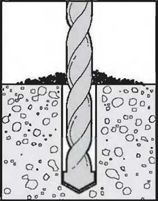
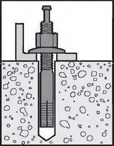
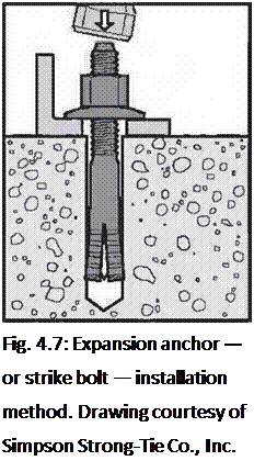
image44image45Подпись: Fig. 4.7: Expansion anchor — or strike bolt — installation method. Drawing courtesy of Simpson Strong-Tie Co., Inc. In areas of high winds, positioning pins alone may not satisfy local code, and you will probably have to use a code-approved metal fastener for the purpose. But, before we look at these, we should discuss metal fasteners and connectors in a general way.
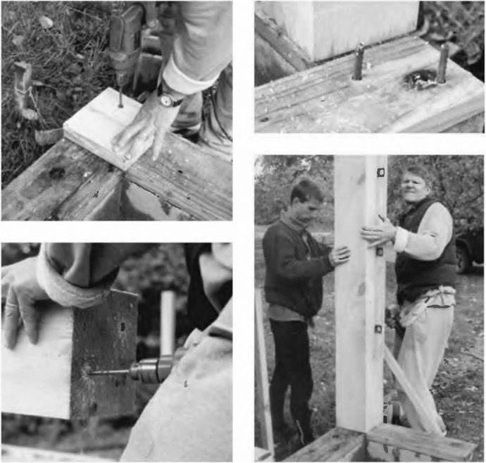
image47

ENGINEERED WOOD PRODUCTS

Engineered wood products have been around for years, particularly in the form of plywood, glu-lam beams, and metal-plate-connected wood trusses. I-joists are more recent, as are LVLs (laminated veneer lumber), PSLs (parallel strand lumber), and LSLs (laminated strand lumber).

It is not the intent of this chapter to explain everything there is to know about engineered wood products, but rather to make you familiar with this category of materials, and give you a sense of what to look out for when you are working with them.

Engineered wood products (EWP) fit into two general categories, engineered panel products (EPP) and engineered lumber products (ELP). The

first group includes plywood, oriented strand board (OSB), waferboard, and composite and structural particleboard.

The second group includes I-joists, glu-lam beams, metal-plate-connected wood trusses, and structural composite lumber (LVLs, PSLs, and LSLs).

Engineered Panel Products

Engineered panel products are so common that their uses are defined in the building codes.

Specific applications vary from job to job, and from manufacturer to manufacturer.

Oriented Strand Board & Waferboard

Most building codes recognize oriented strand board and waferboard for the same uses as plywood, as long as the thicknesses match.

Working with Engineered Panel Products

When working with any engineered panel products, keep the following guidelines in mind:

1. On floors and roofs, run the face grain perpendicular to the supports (except with particleboard, which has no grain). See “Using Engineered Panel Products" illustration.

2. Do not use any piece that does not span at least two supports for floors and roofs.

3. Allow a gap of at least Vs" on all edges, and a gap of more than 1/s" if the piece will be exposed to a lot of moisture before the siding is installed. Note that this also applies to walls.

4. Follow manufacturers’ recommended installation directions.