TESTING THE FINISHED LAYER

A series of acceptance tests are carried out after finishing the placement of a mix­ture. They usually comprise measuring the content of air voids and the compaction factor, conducted on specimens of cores taken from the finished pavement. In many countries, nuclear density gauges are used for testing the homogeneity of compac­tion. When this is the case, cores are only required for calibration and comparisons with the nuclear gauge. Other properties checked on finishing the layer are skid resistance and the macrotexture depth. The methods used for these tests depend on national specifications.

10.6.1 Air Voids in a Compacted SMA Layer

The content of voids in the compacted SMA layer is the most commonly found parameter checked at the acceptance of a finished layer and is always mentioned as a fundamental. According to most analysis documents worldwide, the content of air voids should be lower than 6.0% (v/v). Lately in German guidelines ZTV Asphalt-StB 07 (September 2008 issue), this value has been lowered to 5.0% (v/v). This is the requirement most closely related to the durability of the compacted layer, including its susceptibility to water permeability, frost heave, and deicers. In countries with no significant drops of temperature below 0°C, higher contents of voids in the SMA layer (e. g., up to as much as 5-8% [v/v]) have usually been permitted.

An insufficient content of voids in a layer is also disadvantageous; recent expe­rience shows that less than 3% (v/v) brings about the risk of premature rutting. It has been underlined in the literature (Voskuilen, 2000, Voskuilen et al., 2004) that when designing SMA with a determined content of voids in laboratory speci­mens (usually 3-4% [v/v]), one should remember that the final amount of voids in a compacted layer depends, among other things, on the arrangement of skeleton particles and voids among them. The air voids achieved in a layer on a work site are different from those achieved in the laboratory, just as particles compacted using a Marshall compactor are arranged differently than those that are rolled. Some authors (Voskuilen, 2000) also claim that during the life of the pavement, the content of voids in an SMA layer decreases due to the gradual decrease of voids in the chipping skeleton (e. g., postcompaction, crushing particles). That is why, for instance, in the Netherlands, designing SMA with an initial (laboratory) content of voids at the level of about 5% (v/v) has been practiced. Then, after some time of service, the air void content in the field was lowered to 2-3% (v/v) (Figure 10.13).

Determinations of availability and unavailability

Determination of the availability or unavailability of a system requires a full accounting ofthe failure and repair processes. The basic elements that describe such processes are the failure density function ft (t) and the repair density func­tion gt (t). In this section computation of the availability of a single component or system is described under the condition of an ideal supportability. That is, the availability, strictly speaking, is the inherent availability. Discussions of the subject matter for a complex system are given in Chap. 7.

Consider a specified time interval (0, t], and assume that the system is ini­tially in an operating condition at time zero. Therefore, at any given time in­stance t, the system is in an operating state if the number of failures and repairs w(0, t) are equal, whereas the system is in a failed state if the number of failures exceeds the number of repairs by one. Let NF (t) and Nr (t) be the random vari­ables representing the numbers of failures and repairs in time interval (0, t], respectively. The state of the system at time instance t, failed or operating, can be indicated by a new variable I (t) defined as

I (t) = Nf (t) – Nr(t) (5.45)

Note that I(t) also is a random variable. As described earlier, the indicator variable I (t) is binary by nature, that is,

Подпись: I(t)1 if system is in a failed state

0 otherwise

Recall that the unavailability is the probability that a system is in the failed state, given that the system was initially operational at time zero. Hence the unavailability of a system is the probability that the indicator variable I (t) takes the value of 1, which is equal to the expected value of I (t). Accordingly,

U(t) = E [I (t)] = E [Nf (t)] – E [Nr(t)] = W(0, t) – Г(0, t) (5.46)

indicating that the unavailability is equal to the expected number of failures W(0, t) minus the expected number of repairs Г(0, t) in time interval (0, t]. The values of W(0, t) and Г(0, t) can be computed by Eqs. (5.43) and (5.44), respectively.

To compute W(0, t) and Г(0, t), knowledge of the unconditional failure in­tensity w(t) and the unconditional repair intensity y(t) is required. The un­conditional failure intensity can be derived by the total probability theorem as

w(t) = ft(t) +( y(t) ft(t – r) dr (5.47)

0

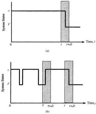
in which, on the right-hand side, the first term, ft (t), is for the case that the probability of failure is at time t, given that the system has survived up to time t; the second term accounts for the case that the system is repaired at time r < t and later fails at time t. This is shown in Fig. 5.18.

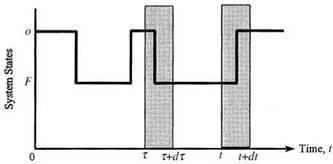
For the unconditional repair intensity y (t) one would need only to consider one possible case, as shown in Fig. 5.19. That is, the system is in an operating state at time t given that the system is operational initially and is in a failed state at time r < t. The probability that this condition occurs is

Y(t) = [ w(r)g(t – r) dr (5.48)

0

Determinations of availability and unavailability

Determinations of availability and unavailability

Figure 5.18 Two different cases for a system to be in a failed state during (t, dt]: (a) the system has been operational up to time t and failed during (t, t + dt), given that it was good at t = 0 and no repair has been done during (0, t); (b) the system has been operational up to time tand failed during (t, t + dt), given that it was good at t = 0 and was repaired at t = т. (After Henley and Kumamoto, 1981.)

Determinations of availability and unavailability

Note that given the failure density ft(t) and the repair density gt(t), the un­conditional failure intensity w(t) and the unconditional repair intensity y(t) are related to one another in an implicit fashion, as shown in Eqs. (5.47) and (5.48). Hence the calculations of w(t) and y (t) are solved by iterative numerical integration. Analytically, the Laplace transform technique can be applied to derive w(t) and y(t) owing to the convolution nature of the two integrals.

Based on the unavailability and unconditional failure intensity, the condi­tional failure intensity g(t) can be computed as

w(t)

1 – U (t)


w(t)

At)


g(t)


(5.49)


which is analogous to Eq. (5.3). For the repair process, the conditional repair intensity p(t), unconditional repair intensity y(t), and unavailability are re­lated as

p «> = ш (550)

The general relationships among the various parameters in the failure and repair processes are summarized in Table 5.4.

TABLE 5.4 Relationship among Parameters in Time-to-Failure Analysis

Repairable systems

Nonrepairable systems

General relations

A(t) + U (t) = 1

A(t) + U (t) = 1

A(t) > ps(t)

A(t) = ps(t)

U(t) < pf (t)

U(t) = pf (t)

w(t) = ft(t) + f ft(t – r)y(t) dr

w(t) = ft (t)

Y(t) = Jgt(t – r)w(r) dr

Y(t) = 0

W(t1, t2) = Jw(r)dr

W(t1, t2) = ps(t2) – ps(tx)

r(t1, t2) = f Y(r)dr

r(t1, t2) = 0

U(t) = W(0, t) – Г(0, t)

U(t) = pf (t)

!i(t) = w(t)/A(t)

h(t) = ft (t)/ps(t)

p (t) = y (t)/U (t)

r(t) = 0

Stationary values

MTBF = MTBR = MTTF + MTTR

MTBF = MTBR = to

0 < A(to), U(to) < 1

A(to) = 0, U(to) = 1

0 < w(to), y(to) < to

w(to) = 0, y(to) = 0

w(to) = y (to)

w(to) = y (to) = 0

W(0, to) = Г(0, to) = to

Remarks

W(0, to) = 1, Г(0, to) = 0

w(t) = Mt), Y(t) = p(t)

w(t) = Mt), Y(t) = p(t) = 0

Mt) = h(t), p(t) = r(t)

p,(t) = h(t), p(t) = r (t) = 0

w(t) = ft(t), y(t) = gt(t)

w(t) = ft(t), y(t) = gt(t) = 0

SOURCE : After Henley and Kumamoto (1981).

Example 5.12 For a given failure density function ft(t) and repair density function gt(t), solve for the unconditional failure intensity w(t) and the unconditional repair intensity y(t) by the Laplace transform technique.

Solution Note that the integrations in Eqs. (5.47) and (5.48) are in fact convolutions of two functions. According to the properties of the Laplace transform described in Appendix 5A, the Laplace transforms of Eqs. (5.47) and (5.48) result in the following two equations, respectively:

L[w(t)] = L[ ft(t)] + L[y(t)] x L[ ft(t)] (5.51a)

L[y(t)] = L[w(t)] x L[gt(t)] (5.51b)

Determinations of availability and unavailability Подпись: (5.52a) (5.52b)

in which L(-) is the Laplace transform operator. Solving Eqs. (5.51a) and (5.51b) simultaneously, one has

To derive w(t) and y(t), the inverse transform can be applied to Eqs. (5.52a) and (5.52b), and the results are

Подпись: L [ ft (t)] 1 (5.53a) 1 - L[ ft(t)] x L[gt(t)]  L[ ft(t)] x L[gt(t)] 1 1 - L[ ft(t)] x L[gt(t)] J (5.53b) Подпись: w(t) = L 1 Y (t) = L-1and

Example 5.13 (Constant failure rate and repair rate) Consider that the failure den­sity function ft(t) and the repair density function gt (t) are both exponential distribu­tions given as

ft(t) = Xe Xt for X > 0, t > 0

gt(t) = ne—qt for n > 0, t > 0

Derive the expressions for their availability and unavailability.

Solution The Laplace transform of the exponential failure density ft(t) is

/•TO /»ТО X

L[ ft(t)] = e-st ft(t) dt = X e-(s+X)t dt = ——————

Л J0 X +s

Determinations of availability and unavailability Подпись: 1 s Determinations of availability and unavailability

Similarly, L[gt(t)] = n/(n + s). Substituting L[ ft(t)] and L[gt(t)] into Eqs. (5.52a) and (5.52b), one has

Подпись: L [Y(t)](Л _X^( 1

X + n s f X + n s + X + n )

Determinations of availability and unavailability

Taking the inverse transform for the preceding two equations, the results are

The availability A(t) then is

Подпись: (5.59)A(t) = 1 – U(t) = -^ + —e-(k+n)t к + n к + n

As the time approaches infinity (t ^ те), the system reaches its stationary condition. Then the stationary availability А(те) and unavailability U(те), are

А(те) =

n

1/k

MTTF

(5.60)

к + n

1/k + 1/n

= MTTF + MTTR

U (те) =

к

1/n

MTTR

(5.61)

к + n

1/k + 1/n

MTTF + MTTR

Other properties for a system with constant failure and repair rates are summarized in Table 5.5. Results obtained in this example also can be derived based on the Markov analysis (Henley and Kumamoto, 1981; Ang and Tang, 1984).

Strictly speaking, the preceding expressions for the availability are the inherent availability under the condition of an ideal supportability with which the mean time to support (MTTS) is zero. In the case that the failed system requires some time to respond and prepare before the repair task is undertaken, the actual availability is

Подпись: А(те) =Подпись: (5.62)MTTF

MTTF + MTTR + MTTS which, as compared with Eq. (5.60), is less than the inherent availability.

Repairable systems

Nonrepairable systems

Failure process

h(t) = X

h(t) = X

Ps (t) = e-Xt

Ps(t) = e-Xt

Pf (t) = 1 – e-Xt

Pf (t) = 1 – e-Xt

ft (t) = Xe-lt

ft (t) = Xe-Xt

MTTF = 1/X

MTTF = 1/X

Repair process

r (t) = n

r(t) = 0

Gt (t) = 1 – e-nt

Gt(t) = 0

gt (t) = ne-nt

gt (t) = 0

MTTR = 1/n

MTTR = to

Dynamic behavior of whole process

U(t) = X/(X + n)(1 – e-(X+n)t)

U(t) = 1 – e-Xt = Pf (t)

A(t) = n/(X + n) + X/(X + n)(1 – e-(x+n)t)

A(t) = e-Xt = Ps(t)

a(t) = Xn/(X + n) + X2/(X + n)(1 – e-(X+n)t)

w(t) = ft (t) = Xe-Xt

Y(t) = Xn/(X + n)(1 – e-(X+n)t)

Y(t) = 0

W(0, t) = Xnt/(X + n) + X2/(X + n)(1 – e-(X+n)t)

W(0, t) = Pf (t)

r(0, t) = Xnt/(X + n) – Xn/(X + n)2(1 – e-(X+n)t)

О

II

o’

Stationary values of whole process

U (to) = X/(X + n) = MTTR/(MTTF + MTTR)

U (to) = 1

A(to) = n/(X + n) = MTTF/(MTTF + MTTR)

A(to) = 0

ш(то) = Xn/(X + n) = 1/(MTTF + MTTR)

w(to) = 0

Y (to) = Xn/(X + n) = w(to)

Y (to) = 0

TABLE 5.5 Summary of the Constant Rate Model

SOURCE : After Henley and Kumamoto (1981).

Example 5.14 Referring to Example 5.12, with exponential failure and repair density functions, determine the availability and unavailability of the pump.

Подпись: 0.0008 (1 e-0.0208t) 0.0008 + 0.02 0.03846(1 - e-0 0208t)
Подпись: U(t) = —— (1 - e-a+n)t) X + n

Solution Since the failure density and repair density functions are both exponential, the unavailability U(t) of the pump, according to Eq. (5.58), is

The availability A(t) then is

A(t) = 1 – U(t) = 0.9615 + 0.03846e-00208t

The stationary availability and unavailability are

4 MTTF 1/X 1250

A(to) = MTTF + MTTR = I/m/n = 1250 + 50 = a96154 U(to) = 1 – A(to) = 1 – 0.96154 = 0.03846

Determinations of availability and unavailability

TABLE 5.6 Operation Properties of the Laplace Transform on a Function

Property

Function

Variable

Laplace transform

Standard

fx ( x)

X

Lx(s)

Scaling

fx (ax)

X

a-1 Lx (s/a)

Linear

afx(x)

X

aLx (s)

Translation-1

eaxfx (x)

X

Lx (s + a)

Translation-2

fx (x — a)

X

easLx(s), x > a

Appendix 5A: Laplace Transform*

Подпись: eSXfx(X) dx
Подпись: Lx (s) Подпись: — TO Подпись: (5A.1)

The Laplace transforms of a function fx(x) are defined, respectively, as

In a case where f x(x) is the PDF of a random variable, the Laplace transform defined in Eqs. (5A.1) can be stated as

Lx(s) = E [esX] for x > 0 (5A.2)

Useful operational properties of the Laplace transform on a PDF are given in Table 5.6. The transformed function given by Eq. (5A.1) of a PDF is called the moment-generating function (MGF) and is shown in Table 5.7 for some com­monly used probability distribution functions. Some useful operational rules relevant to the Laplace transform are given in Table 5.8.

‘Extracted from Tung and Yen (2005).

Uniform

Eq. (2.100)

ee

(b — a)s

Normal

Eq. (2.58)

exp(/u, s — 0.5s

Gamma

Eq. (2.72)

1/в

a

[(1/в) — s

Exponential

Eq. (2.79)

1/в

(1/в)—s

Extreme value I (max)

Eq. (2.85)

e4 sr(1 — в s)

Chi-square

Eq. (2.102)

(1 — 2s)—K/2

TABLE 5.7 Laplace Transform (Moment-Generating Functions) of Some Commonly Used Distribution Functions

Distribution

PDF Laplace transform

TABLE 5.8 Operational Rules for the Laplace Transform

W = cX Lw(s) = Lx(cs), c = a constant.

W = c + X Lw(s) = ecsLx(s), c = a constant.

Other aqueducts in the Roman Empire

The panorama of Gallo-Roman aqueducts that we have just described represents the diversity of situations and solutions adopted throughout the Roman Empire. Table 6.1 gives an incomplete list of the numerous Roman aqueducts that have been discovered and studied. It would be impossible to describe all of them. To the best of our knowl­edge, the longest one is at Apamea-on-Orontes in Syria, built in 116 or 117 AD as part of the broad reconstruction after the earthquake of 115 AD.[246] But another aqueduct also merits our attention. It is the aqueduct of Carthage, one of the marvels of Roman archi­tecture in Africa, and among the longest of all the Roman aqueducts in the western world (Figure 6.18).[247]

Carthage is destroyed by the Romans at the end of the Punic wars, then rebuilt in 29 BC by Augustus for the purpose of granting property to legionnaires at the end of their service, and then later becomes a capital of the province of Africa. With completion of the great thermal baths of Antonio, it becomes necessary in 162 AD to build an aqueduct to supply numerous public fountains, and also to build cisterns to store rainwater. But the usable water sources are some distance away, in Djebel Zaghouan. The closest source is 56 km away as the crow flies, with obstacles in the way including a lagoon to the east of Tunis, and a saline lake somewhat further. At the wide valley of the wadi Milliane there is a crossing of 4.5 km on arches that are some 20 m high in places, and a two-level bridge 126 m long and 34 m high.[248] In this plain of Carthage there are 17 km of crossings on high arches in all. Later on, very likely under the Severus emperors, the aqueduct is lengthened to 132 km, to capture the even more distant springs of Ain Djoukar.

Other aqueducts in the Roman Empire

Distance from the cistern at Carthage (km)

Figure 6.18 The aqueduct of Carthage: map of the alignment and schematic longitudinal profile (after Rakob, 1979). Only the points indicated (x) are exact, the remainder of the profile is deduced from simple interpolation. The maximum capacity is estimated at 25,000 m3/day.

Like the Pont du Gard in Europe, the aqueduct of Carthage and its appurtenances attract the admiration of African observers:

“This distance, from the source (Ain Djoukar) to the cisterns (the 24 cisterns of Carthage) was covered thanks to an infinite number of aqueducts, in which water flowed at a constant level. These aqueducts were composed of stone arches. When these were on the ground, they were low and when they were in the depressions or valleys, they were extremely high. This was one of the most remarkable things to be seen on the surface of the earth.” [249]

The upstream portion of the aqueduct is still used today by the Tunisian water service.

Final Remarks

The layer edge should be rolled with a machine fitted with a side-roll; this will enable suitable compaction of the area close to the edge. The drums of a roller should be moistened with water, which should protect them against mastic adhesion and drag­ging particles out.

10.5 pLAcEMENT of sMA IN KOMPAKTASPHALT TEcHNIQuE

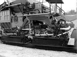
The Kompaktasphalt method consists of placing two layers of a pavement in one pass of a specially designed paver (Figure 10.12). Typically the paver places both an SMA and asphalt concrete in one pass. The first attempt at such a laydown occurred

image104

FIGURE 10.12 Special paver for the placement of two layers in one pass with an SMA wearing course (A2 highway in Poland), an example of Kompaktaspha. lt technology. (Photo courtesy of Konrad Jablohski.)

in 1995 Germany and was made by Elk Richter of Fachhochschule Erfurt and the company Hermann Kirchner GmbH&Co KG on Highway A4 (Richter, 1997). In December 1998, also in Germany, a special modular paver was used for the first time (Utterodt and Egervari, 2009). This technology has been chiefly applied in Germany. Undoubtedly, the simultaneous placement of two layers has a number of strong points. It is enough to mention just the following:

• Excellent interlayer bonding (i. e., the “hot-on-hot” placement)

• Great thermal capacity of the two layers together (thickness of 10-12 cm), giving more time for compacting, especially on cool days

• Rapid progress in work (two layers at the same time)

The use of the Kompaktasphalt technology carries with it some additional require­ments for the construction site organization:

• The mixture intended for a particular site comes from two, sometimes even three, asphalt plants with sufficient capacity to supply the paver.

• An adequate number of transport vehicles are essential to haul mixtures from asphalt plants to the construction site.

This frequently adopted scheme provides for the placement of an asphalt concrete intermediate layer and an SMA wearing course. Various thicknesses and gradation of SMA layers are used, with 4-cm of SMA 0/11 mm and 3-cm of SMA 0/8 mm being used most often.

Organic Mastics

Organic mastics are either water – or petro­leum-based adhesives that consist of a bonding agent and a liquid vehicle. For petroleum – based mastics, the vehicle is a solvent, usually toluene. These formulations are highly toxic and flammable and are not recommended for use in a healthy home.

Organic mastics enjoy widespread popu­larity because they are inexpensive, stickier than thinsets, and allow the quickest installa­tions. However, they do not have the strength, flexibility, or water resistance of thinset or thickset applications. Because they are applied in a very thin layer, they do not have leveling capabilities and are suitable only for applica­tion over flat surfaces such as plywood or dry – wall. When they are used over concrete, the vapor emission rate and pH of the slab must be checked to ensure compatibility with the mastic, which can break down if too much moisture is emitted from the slab. If the slab is too alkaline, adverse pH reactions in the mastic can result in a persistent odor that is strong and unpleasant. Refer to Division 13 for more information on calcium chloride mois­ture testing and pH testing for concrete. Most mastics are not recommended for areas that get wet. Where mastic applications are appro­priate, you may wish to choose one of the fol­lowing water-based products:

• AFM Safecoat 3 in 1 Adhesive: Low-odor, low-VOC, water-based mastic for hard composition wall and floor tiles

• CHAPCO Safe-Set 88 and Safe-Set 90 Ce­ramic Tile Adhesives: Solvent-free, non­flammable, freeze/thaw stable, and almost odor-free ceramic floor tile adhesives

• Taylor Envirotec 901 Odyssey Ceramic Tile Type I Adhesive: For ceramic floor and wall tile adhesion

Grouts

As with tile-setting mortars, a number of addi­tives maybe used in commercial grouts to im­part certain performance characteristics such as improved strength and flexibility, increased water or stain resistance, and improved freeze/ thaw stability. Some of these additives, such as epoxies, are quite noxious. In grout applica­tions, they will be exposed to the living space and will continue to outgas until completely cured. Homemade grouts can be mixed on­site by combining Portland cement, sand, lime (optional), and water. They can be colored with the same pigments used to color concrete (see the section on concrete finishes in Divi­sion 3). It is important that the person mixing the grout know the proper proportions and sand size for the particular tile application. These applications should be damp-cured for three days. The following commercially avail­able grouts are free of latex additives:

• C-Cure AR Sanded Grout 922: A sanded grout available in a limited selection of colors

• C-Cure Supreme Grout 925: An unsanded grout for joints less than % inch and for use with tiles that are easily scratched, such as marble

• Hydroment: Ceramic tile grout (sanded) and dry tile grout (unsanded)

• Mapei 2V2" to 1: For large grout joints greater than % inch

• Summitville-700 SummitChromes:

Sanded grout without polymer additives, available in 32 colors

Sealers

Tile Sealers

If an unsealed tile is selected, it is important to specify sealants that are free of harmful chem­icals. Many of the commercially available tile sealers are solvent-based, highly toxic prod­ucts that will emit noxious fumes for a long time after application. If they are used to cover a large floor area, the negative impact can be significant. Consider one of the following spe­cially formulated products:

• AFM Safecoat MexeSeal: For sealing pre­viously unsealed tile floors

• AgriStain for Concrete: Sealer and stain for concrete, plaster, and porous tiles

• Zip-Guard Environmental Wood Finish: A water-based urethane that can be used for sealing very clean, previously unsealed tile floors

Execution

So far, this chapter has described the sensibility, the principles, and the tools inherent to successful architecture. This next section explains the actual pro­cess of subtractive design and relevant considerations. Compared to what is involved in producing large houses, planning a little home is relatively challenging. As stated earlier, a smart, little dwelling is just like an oversized house with the unnecessary parts removed. Editing a structure down to its essence takes patience, but so long as one has this and abides by these instructions as well as necessity, the effort will not go unrewarded.

Get the right tools. There are as many techniques for putting architec­tural ideas down on paper (or screen) as there are people putting them down there. The best way I have found is with a.05 mm technical pencil, a Tuff Stuff retractable eraser, an 8 1/2” x 11” pad of 1/8” grid paper, a transparent ruler and a simple compass for making arcs. I know there are a lot of people out there who will swear by computer programs like CAD. My own experi­ence with such programs is that they are great for tidying up finished designs but are no match for pencil and paper when it comes to the creative part of the process. Fluidity is essential, in any case.

Keep the process fluid. Writer’s block is not exclusive to writers. It can happen to any artist who forgets to keep an eye on the big picture. Because a successful composition is only possible when every one of its parts is integral to the whole, it makes sense that the whole must be more or less established before any part can be fully developed. The whole informs the shape and function of its parts. Work from the most general elements of the composition toward the more specific details within.

Do not consider anything too precious for revision until a composition has been established, the house has been proven to work perfectly. Expect to go through more eraser than graphite. Every mistake is a step forward, as it further illuminates what is not necessary and, thus, points the way to what is. Ninety percent of the process will be messy and temporal. Clean lines will only be introduced once the real work has been done.

Know what is needed. The process begins with general considerations and broad forms. Before proceeding, a list of domestic necessities, like the one provided on pages 89 – 92, should be developed according to the inhab­itant’s needs and those posed by the local environment.

Determine the shape of the house. Spherical forms have the least amount of surface area, so a dome is bound to need a bit less heating and cooling than something with square corners. On the other hand, domes are prone to leaks and are far more difficult to compose than rectilinear shapes. Right-angled forms invariably mesh with other right-angled forms, so books fit easily onto shelves, shelves into corners, corners into rooms, rooms into houses, houses into lots and lots into communities.

Buildings with flat roofs have become quite popular over the past century or so. The trend began in Europe, where elaborate roofs with lots of orna­ments had become symbolic of the ruling class. Modernism stepped in to provide homeowners with the exact opposite of the ornate option. Flat roofs represented the more respectable, utilitarian lifestyle of the proletariat. Once Modernism hit America, it became the perfect excuse for putting up a lot of cheap buildings. Aside from adding unnecessary square footage, about the easiest way for builders to make more money for less is by sticking a flat roof on their structures.

Flat roofs may be all well and good when used in the most arid deserts of the U. S., but when used elsewhere, they tend to spring a lot of leaks or collapse. In such cases, the complexities of simplification become all too clear. By all means, that which is unnecessary to a design should be eliminated, but only after what is necessary has been determined.

Just as bees build with hexagons and cubitermes termites go for domes, we, as a species, tend to produce a lot of 90-degree angle walls and pitched roofs. It just seems to make sense for us. Rain and snow are a part of most of the climates we live in, and a slanted roof sheds these elements like noth­ing else can. Of course, flat roofs and domes are exactly what are needed in some situations, and, as always, necessity should be heeded.

Determine the approximate size. I know people who live in just sev­enty square feet. I know other folks for whom living in anything less than ten times that might be difficult. Houses are not a one-size-fits-all product.

Lists detailing the amount of space needed for appliances and elbow room, as well as wall, floor and ceiling thickness are provided at the end of this chapter. Reference these as you proceed to determine and organize special needs.

If this is to be a place for yourself, you will have to figure out how much physi­cal space is required for all of your things, for yourself, for other occupants and their stuff, and for guests. Remember that, with all of the money that will be saved by building a smaller dwelling, outsourcing hotel ball rooms for big parties will now be a viable way to extend your home beyond the limitations of the house itself. Your little abode should not be thought of as an autono­mous structure, but more as the most private realm within a much broader system.

Calculating how much space is needed for your stuff is a pretty straight­forward task. First, get rid of anything you do not need. Then, round up all your possessions and a measuring tape. Consider how many of the things will require closet space, how many will go on book shelves, in the kitchen, near the kitchen sink, and so on. Then proceed to determine how much open space you need for your own comfort. You will probably want one relatively – large, main room. To determine its size, find a smallish enclosure that is fairly uncluttered. Does it feel like a comfortable amount of space? How tall does it need to be? Consider what kind of activities you will be doing in your main room. If you anticipate some yoga, determine how large an area that requires. Office cubicles, bathroom stalls and walk-in closets are some places you might consider evaluating. Never mind the puzzled looks you will undoubtedly receive from others

Sketch your rooms. Once you have an idea of how much open area you require, draw a bird’s-eye view of the main room on a piece of grid paper. Be sure to add some square footage around the edges for furnishings and storage. To keep its center unobstructed, most of the furniture will need to be kept on the periphery, along with some empty space for accessing windows and doors.

Detailed calculations should be saved for later. For now, just continue to cat- categorize your things into areas and make to-scale drawings of any other rooms you plan to include. Keep the center of these spaces open too.

Cut the drawing of each room out and place all of them together as you ima­gine them fitting together in a house. If they do not add up to a simple, Euclid­ian shape, like a square, circle, rectangle or triangle, you may want to adjust their proportions until they do. Generally, the more corners there are on the outside of a house, the more surface area there will be to lose heat and A. C., the more materials and labor will be required, and the more complex and po­tentially leaky the roof will be. Four or five exterior corners are usually plenty. Anything with more than ten or so may become problematic. Alignment is particularly important for the outside of the house. Four, unbroken walls are generally better than a bunch of divided ones.

Consider portals. Decide how the rooms will be connected by doors and how the house will be connected to the outside world by windows and door(s). Think about how the placement of doors and windows will make the home’s exterior read in terms of alignment and proportion. Unless your plan is intended for a very warm climate, try to locate most of the windows on the south side and few, if any, on the north. South-facing windows allow for solar gain. North-facing windows allow for winter heat loss.

Along these same lines, be sure to provide seasonal shade for south-facing and west-facing windows. Deciduous trees work to this end, as their leaves provide summer shade and drop to reveal the winter sun. Awnings and porch roofs achieve the same effect by protecting windows from the relatively verti­cal rays of the summer sun while allowing the more horizontal rays inside.

Sliding doors, curtains and pocket doors can often save space as, they do not require an area in which to swing.

Minimize throughways. Hallways and oversized stairwells unnecessar­ily consume valuable space. If a stairway is required, consider making it a ladder. Paddle steps can also save space.

Make use of vertical space. Shelves can usually go all the way to the ceiling; drawers can be put beneath the bed, cabinets can often be posi­tioned over the table, and a sleeping loft may fit below a high ceiling.

Consider using built-in furniture and storage in your design.

Freestanding furniture tends to leave awkward and unusable margins on both sides of where it is positioned. Built-ins generally stretch from wall-to – wall, and often floor-to-ceiling, to make use of every inch.

Built-ins are not only integral to a house in terms of function and structure, but in visual terms as well. Freestanding armoires, chests, and bookcases will fill up a small room quickly and tend to make any space feel more crow­ded. A wall of built-in cabinets can contain more possessions than all of these combined and comes off as far less visually intrusive. Built-in seating, cabin­ets, bookcases, work surfaces, and dining nooks can all be used to save and order space in this way.

Consider including some shallow shelves. Putting all of your glasses, vita­mins and herbs on one deep shelf is going to demand that you dig for stuff that sits at the back. Less depth will put everything where you can get to it.

Carve out places near the door for the things that enter and leave your home: coat hooks, shoe cubbies, recycling bins, and the like.

Keep it simple. It is particularly important that a place for one be kept sim­ple. For a single resident, all of the little extras can quickly add up to one big headache. The housing market currently offers very few properties designed specifically for one person. More often than not, those of us who choose to live alone end up saddled with the responsibilities of a house or apartment that was built for two or more residents.

Tumbleweed Tiny House Company’s XS-House

The design of a single-occupancy dwelling is unique in that it requires rela­tively few, if any, interior walls. One room is often enough to contain every­thing that is necessary. Sometimes a separate little bathroom, kitchen, sleep­ing loft and/or closet can be useful, but the principal aim should be to keep things open. That said, it should be remembered that arbitrarily eliminating as many interior walls as possible will not necessarily result in a better space. While floor area and elbow room are inevitably gained, wall space is lost. This may affect the possibilities for furniture placement and storage options. Open-concept layouts are great so long as they truly correspond with the necessities at hand.

Provide privacy and community. Designing a house for two or more people entails largely the same process, but the big room has to accommo­date enough open space for all of the home’s occupants to feel comfortable, and a small private area should be provided for every member of the house­hold. Our need for a balance of both privacy and community is inherent, and if it is ignored in the design of a dwelling, strife will inevitably result. The private areas can be rooms, entire apartments within the structure, or even physically separate cottages. To increase the effectiveness of the private rooms within a house, closets should be located between them as sound buffers whenever it is possible.

These little private realms should be arranged around a shared larger area. One form that has been proven to work quite well as a shared space is the farmhouse kitchen mentioned earlier. In this case, the kitchen is also the din­ing room and the family/living room. It is designed to contain the dining table and cooking facilities, and enough space to serve a variety of functions.

In the common area of a shared household (be it inside or out), traffic zones and activity zones need to be kept apart. Unlike the space in a one-person residence or a private room, people will be passing through the common area regularly, so projects need to be kept out of traffic’s way. Provide activity nodes at the area’s periphery to keep the center wide open.

Keep it light. Light colors tend to make a space feel more open, while dark ones will make the same space feel crowded.

Make it flexible. If your desk can double as a dining table, so much the better. Mobile bookcases and cabinets can be used as room dividers, then moved out of the way for activities that require more space. A Murphy bed can transform an office into a guest room in seconds. Folding tables and chairs allow for further flexibility.

Extend sight lines to make small rooms feel more generous.

Views from one part of the house into another or to the outdoors will make that part feel more expansive.

Keep clutter out of sight and, thus, out of mind. This goes a long way to improve how we experience a space. Be sure to include areas where clutter, or even everyday items, can be stored away and hidden from view. An uncluttered house will result in an uncluttered mind and unfettered creativity.

Take advantage of the outdoors whenever possible. Outdoor rooms add functional space without the added cost of water-tight, insulated construction.

If necessary, sacrifice space for the illusion of space. Our per­ceptions of spaciousness often have more to do with perception itself than actual volume. Occasionally, it will become necessary to sacrifice actual space to achieve a design that feels more open. By lowering the ceiling in one area, for example, the volume in a neighboring area will generally ap­pear to increase.

Remember the invisible parts. With the basic shapes and sizes more or less established and in place, more attention can now be paid to arranging any furnishings or integral elements. Do not forget to include room for pipes and heating ducts if any are needed. Keep the plumbing as localized as pos­sible. If the water heater is at one end of the house and the shower is at the other, you will have to wait a long while for hot water when you go to bathe.

Keep refining. As the floor plan becomes clearer, feel free to add some details and to eliminate any unused or unusable parts. To read as a strong composition, every square inch of your house should be contributing to the whole structure and its function. Feet, inches and quarter-inches can be shaved off as the design begins to reveal its own needs. Before things get too finite on the inside, make scale drawings of the front, back and sides of the structure to determine what changes may need to be made there.

Align everything that can be aligned. Consider the hierarchy of the place. Lower ceilings and enlarge some doorways, if necessary. So long as necessity is allowed to make the decisions, all of this should come pretty naturally. Remove yourself from the process and let nature take over. The resulting home will be beautifully simple.

Time Available for Compaction

The time available for compacting the layer depends mainly on the following condi­tions during placement:

• The mixture temperature behind the paver

• The air and surface temperatures and wind velocity

• The layer thickness

The matters of temperature are elaborated on in Section 10.3.2.

In extremely adverse weather conditions, the time for compacting is counted in minutes and is often less than 5 minutes. After that time, the mixture temperature falls to a level at which the high viscosity of binder makes the movements of the mix­ture particles impossible. If the SMA layer has to be placed in difficult conditions, the following organizational issues should be remembered:

• Using the best possible insulation during SMA mixture delivery

• Closely coordinating the mixture deliveries in relation to the spreading speed with no stoppages and shutdowns of the paver or trucks delivering mixture to a work site

• Discharging consecutive mixture deliveries to the paver hopper before it is completely emptied

• Effectively heating of the paver screed

• Maintaining the proper paver speed to avoid the following:

• Decreased effectiveness of the paver compaction

• The risk of dragging chipping particles out by the screed

• Keeping the rollers close behind the paver and having more of them than when compacting in good conditions

• Calculating the limited time of effective rolling caused by the drop of mix­ture temperature in the layer; being aware of weather conditions, the tem­perature of a delivered mixture, and the layer thickness, one can roughly estimate the time required for compacting using ready-made curves, mea­suring the layer cooling rate, or calculating it with the use of computer software such as PaveCool or MultiCool.

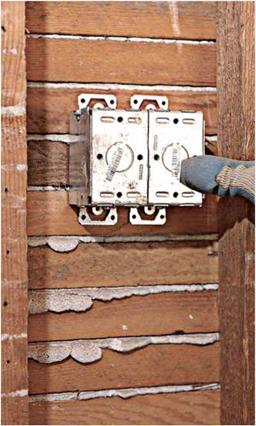
Adding Outlets to Existing Circuits

Adding an outlet may be relatively simple if you can access an existing outlet and run a length of cable to a new outlet in the same wall cavity. But even the simplest setup needs a bit of planning— and some exploration—beforehand.

IMPORTANT PREP STEPS

Here are some tasks to do before working in an existing circuit:

► Check local electrical codes, which may not allow extensions of ungrounded circuits. The NEC forbids tying into specialized kitchen, bathroom, or dedicated-appliance circuits.

The circuit you tie into must be a 15-amp or

20- amp general-use or lighting circuit.

► Using a circuit map like that shown on

p. 234 will help you calculate how much power the new circuit will draw. Add up the wattage of all lights and appliances you’ll use on the circuit—plus that of tools if it’s an outdoor outlet. If the total exceeds 1,440 watts for a 15-amp circuit, you’re better off installing a new circuit to serve the new outlets.

►0 Turn off the power and test all affected outlets—including switches—with a voltage tester to make sure the power is off (see "Using a Voltage Tester," on p. 235). If you flip a circuit breaker to cut power, tape the service-panel door shut and put up a sign warning others of work in progress.

► Using cordless tools with plastic housings also reduces the risk of shock. Wear protection if you use power tools.

► After testing verifies that the power is off, unscrew the receptacle and gently pull it from the wall so you can check the capacity of the box. If the box is already crowded—which you can tell just by looking—there may not be room for an additional cable. Consult the table "Box Fill Worksheet, " on p. 240, to be sure. It is possible to replace the existing box with a larger one, but that will complicate

the task.

POSITIONING NEW OUTLETS

After deciding where you’d like a new outlet, find an existing outlet close to it. Think spatially: The closest outlet may be on the other side of a wall or on a floor above or below. Any existing outlet
is a likely candidate as long as it is live all the time—and not controlled by a switch upstream.

That decided, next figure out how to run cable with a minimum of drilling, wire fishing, and destroying of finished surfaces. If the nearest existing outlet is on another floor, look for a wall that contains plumbing that runs from floor to floor (a “pipe chase”). Also, there’s often room to run cable in the voids around stairwells. Closets that line up vertically are also good places to hide cable, patched walls, and discrete holes.

Drilling through wall plates. If there’s an un­finished attic or basement, you may be able to locate a wall in which to run cable by noting where existing cables or pipes emerge, where sole plates have been nailed through a subfloor, or where attic joists rest on wall top plates. When dropping cable down from above, first drill two pilot holes in the top plate—one hole to shine a flashlight into, the other to look into—to see if

A 4-ft. flexible drill bit is one way to drill through wall plates to reach a power source below. Because its diameter is less than ’A in., the bit shaft tends to wander. Wear heavy gloves so you can guide the bit without hurting your hands. Drill slowly.

INSTALLING A CUT-IN BOX

Ideally, a cut-in box should be positioned so that you need to remove only one complete lath strip and so the box’s plaster ears can be screwed into lath strips that are continuous.


image521

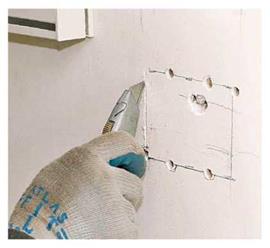
1. After test-drilling to locate the edges of a lath strip, level and outline the box, and drill several holes for a jigsaw blade—the more holes, the better. Before sawing, score the outline to minimize plaster cracking.


image520

there are obstructions such as fire-stops in the stud bay. Professionals sometimes have a helper stand near an outlet they’re drilling toward, who lightly places his or her hand on the wall to tell if a bit is on target. (You can feel the vibration of the bit.) Obviously, this takes skill and slow, care­ful drilling to avoid goring the helper.

Another approach: Drill exploratory holes by facing the outlet and angle drilling a Мб-in. hole at the base (or top) of the wall. Once the Мб-in. bit hits open space, insert a length of coat hanger or wire to find the hole more easily, above or below. If exploratory holes are in the right place, use a 18-in. bit to enlarge the holes.

If there’s no accessible attic or basement, you may need to cut small holes at the top or base of finish walls so you can angle-drill through wall plates and fish cable. For this you may need to pull back carpeting or remove baseboard mold­ing temporarily.

Behind baseboards. Running cable behind baseboards may be the best way to minimize damage to plaster or drywall. О First, turn off power to the area, and check to be sure it’s off; then remove the baseboard trim. If you use a nail set to drive finish nails through the trim, you’ll be less likely to break it. Once the baseboards are off,
use a cordless circular saw to cut along the bottom of the finish wall, 3 in. to 4 in. up from the floor. Set the sawblade to the depth of the finish surface so you don’t cut into studs or through electrical cables hidden in the walls. (Wear safety glasses.) Use a flat bar to pry up the finish wall slot.

Next, create a pathway for running the cable by drilling holes through studs; by notching stud edges !2 in.; or by cutting a slot in the back of the baseboard, if it’s thick enough. Whatever approach you choose, install Иб-in. steel nail – protection plates afterward to keep screws or nails from puncturing the cable.

Alternatives to Gypsum Board

Alternatives to paper-backed gypsum board are now available. The following products may be used to replace it and are especially use­ful in applications where moisture conditions may promote mold growth:

• Dens Armor Plus is an alternative to regu­lar cardboard-backed panels. It is paper­less, faced on two sides with a glass mat, and highly mold resistant.

• Magnesium oxide boards: Currently these products are being manufactured in China. They can be used to replace gypsum board, plywood, cement boards, and oriented strand board (OSB). They resist moisture, bugs, fungus, mold, and fire. Products are available in North America under the prod­uct names Dragonboard, MagBoard, and Strong-Enviro Board.

Tile

Tile is generally an inert and healthful floor, wall, and counter surfacing material. We rec­ommend factory-finished tiles that require no further finishing onsite. Many attractive and reasonably priced tiles are rated for com­mercial and exterior use. This rating almost guarantees a low-maintenance, long-wearing product that will not require onsite refinish­ing.

The following concerns must be addressed in order to achieve a healthful installation:

• In standard construction, tile is often laid over an unacceptable backing such as par­ticleboard, which contains high formalde­hyde levels.

• In wet areas, tile is frequently laid over green board (a gypsum board that has par­affin wax mixed with the gypsum to pre­vent it from falling apart). However, the paper on the board will still develop mold in the presence of moisture.

• Certain imported tiles contain lead-based glazes or asbestos fillers. Lead content can be simply verified with a lead swab test (see Chart 13 л).

Подпись: Ceramic tile slate and glass create this shower enclosure that brings views of the beautiful surroundings into this bathroom. Architect: Baker-Laporte and Associates; Builder: Prull and Associates. Photo: Julie Dean. Certain glazes, primarily imports, have been found to be radioactive, especially cobalt blues and burnt oranges.

Alternatives to Gypsum Board

Alternatives to Gypsum Boardсокт

Alternatives to Gypsum Board

PBTAl МТЙ 4W ШШб"

ШпЖ

H^^NPV

&&, w>

Thick-set tile installation.

• Many tile-sealing products contain harm­ful chemicals and high levels of VOCs. Selecting tiles with commercially rated finishes and glazes will bypass the need to use tile sealers on the construction site.

• Some standard tile adhesives and mortars contain harmful chemicals.

• Standard grouts usually contai n fungicides and latex additives.

• Grouts are porous and can harbor mold and mildew. They should be sealed where exposed to water.

Underlayment for Ceramic Tile

The following are acceptable underlayments for ceramic tile:

• A clean, level concrete slab or gypsum con­crete base that has been fully cured.

• Exterior-grade plywood that has been aired out and sealed. Use only where a ce­mentitious underlayment is unavailable.

This method will require mastic adhesive and is not recommended for areas that get wet.

• A lightweight, strong, noncombustible, highly water-resistant cementitious board such as Durock, Hardibacker Board, or PermaBase.

Tile Installation

The three basic methods for installing tiles are thicksetting, thinsetting, and adhesion with organic mastics.

Thickset Method

This is the tried and true, old-fashioned way of adhering tiles, prevalent prior to the invention of additives. A thick reinforced bed of mor­tar consisting of Portland cement, sand, and in some cases lime is floated. While the base is still plastic, a thin layer of Portland cement paste known as the bond coat is spread over
it. The tile is adhered to the bond coat and al­lowed to cure for several days before the tile is grouted.

This method will create the strongest, most durable tile installation available without the use of chemical additives. The following should be specified for this type of installation:

• Use only additive-free Portland cement, clean sand, lime where required, and po­table water. Use the recommended rein­forcing and specified cleavage membrane.

• For wall, ceiling, and floor installations, follow the method covered by ANSI AI08.1 and set the tiles on the mortar bed while it is still plastic.

• The cleavage membrane shall be non­asphalt-impregnated, 4 millimeter poly­ethylene such as Cross Tuff, Tu Tuf 4, or an approved equivalent.

It is not always possible to use a thickset instal­lation. The iW-inch depth required for thick­setting may not be available unless carefully planned from the outset. Tile setters skilled in this method are sometimes difficult to locate. This method is labor-intensive and will be more costly than other installation methods.

Thinset Method

Tliinset mortars are powdered sand and ce­ment products mixed with liquid and spread to a thickness of approximately Vs to Ys of an inch. Once dried they are unaffected by water and can be used in wet applications.

A variety of thinsets are available. Most thinset mortars contain various chemical ad­ditives to enhance workability, flexibility, and bonding strength, thus expanding the range of application. Water-mixed thinsets consist of powdered sand and cement. They are available with or without powdered latex and acrylic additives and are mixed onsite with water. Latex and acrylic thinsets consist of powdered sand and cement mixed with liquid latexes and acrylics instead of water. They have higher bond and compressive strength and improved flexibility compared to water-mixed thinsets. Epoxy thinsets develop bonds more quickly than other thinsets. The epoxies emit nox­ious fumes while curing and these fumes can be absorbed by porous surfaces. The use of epoxies is almost always unnecessary in res­idential construction. If epoxies are used, workers should wear protective vapor respira­tors during application and the space should be continuously aired out until all fumes have dissipated. The additive ingredients used in these thinset mixtures are proprietary and not disclosed on the label. When selecting a thin­set product, choose one that can do the job at hand with the smallest amount of chemical additives and the least odor.

Thinsets Without Synthetic Additives

The following water-mixed thinsets are avail­able without synthetic additives. They gain their strength through the use of high-quality Portland cement, but are generally considered to be less flexible and more prone to cracking than thinsets with latex additives. They may be used successfully over clean concrete slabs, properly supported cementitious boards, and mortar beds.

• C-Cure FloorMix 900, Thinset 911 (dual purpose), andWallMix9oi: The “economy” line of C-Cure mortars, which contain no additives other than mineral salts

• Laticrete Additive Free Thinset

Low-О dor Thin sets with Vinyl Polymer Additives

The following water-mixed thinsets con­tain vinyl polymers, which give them greater strength and range of application. They have very little odor and are virtually odorless once cured. However, anyone with sensitivities to vinyl polymer additives is advised to test these products prior to using them.

• C-Cure MultiCure 905: A latex-en­hanced, dry-set mortar with added bond­ing strength and flexibility for use over cementitious and plywood substrates

• C-Cure PermaBond 902: A dry-set mor­tar with Portland cement, sand, and addi­tives for use over cementitious substrates

Water Influence on Bearing Capacity

8.2.1 Different Types of Road Structures Versus Sensitivity to Water

Road pavements are multilayer structures (see Fig. 1.5) generally comprising a sur­face course and one or more asphaltic or granular base layers, resting on a pavement foundation. Chapter 1 introduced the major pavement layers – the foundation, the sub-base, the pavement base and a surfacing (see Section 1.4.2).

Water permeability should normally increase from the top of the pavement (the asphalt or concrete layers) downward until about 0.7 m depth (see Chapter 5). Oth­erwise water would accumulate onto the low permeability layer and keep the upper layer wet; freezing of the accumulated water might then unbind the upper layer. This would decrease it’s bearing capacity and service life. An exception to these rules are the porous asphalt surfaced pavements described in Chapter 5, Section 5.7, which are designed to carry water within their thickness.

Pavement structures can be divided in four main groups:

• Thin bituminous pavements, which consist of a relatively thin bituminous sur­face course, resting on one or more layers of unbound granular materials. These are typically used for carrying low traffic levels.

• Thick bituminous pavements consisting of a bituminous surfacing, over one or two bituminous layers/asphaltic concrete (AC) (base) then an aggregate (sub-base). Their application is, typically, for high traffic levels. They may be considered as flexible, but they are much stiffer then the preceding pavements.

• Semi-rigid pavements comprising a bituminous surfacing over one or two layers of materials treated with hydraulic binders (e. g. concrete). This type of pavement is also appropriate for high traffic levels.

• Portland cement concrete (PCC) pavements which consist of a Portland ce­ment concrete slab (15-40 cm thick), possibly covered with a thin bituminous surfacing, resting on a sub-base (bound or unbound), or directly on the foun­dation. The concrete slab can be continuous with longitudinal reinforcement, or discontinuous. Once again, this type of pavement is also appropriate for high traffic levels.

These various pavement types present different types of mechanical behaviour, and different deterioration mechanisms. However, for all structures, water plays a major role in pavement deterioration.

In thin bituminous pavements, high stresses are transmitted to the unbound granular layers and to the subgrade; and lead to permanent deformations of these layers. Because unbound layers and subgrades are sensitive to water content, the performance of these pavements is strongly dependent on variations of moisture conditions. This can lead, in particular to “edge failures”: water infiltrates from the pavement shoulders, under the edge of the pavement, leading to subsidence at road edges. As these pavements are very sensitive to moisture, impermeability of the surface course and good drainage are very important for their performance.

In thick bituminous pavements, the much lower flexibility of their bituminous base layers means that the stresses transmitted to the soil are much lower, and the risk of permanent deformations in the soil, as well as the sensitivity to the wa­ter content of the soil, are lower. The main mechanism of deterioration of these pavements is cracking due to the combined effects of traffic-induced strains and thermally-induced movements, causing high tensile stresses in the bound layers. Once the pavement is cracked, water infiltration accelerates the degradations, lead­ing to weakening of the subgrade, attrition at the lips of the cracks, and material chipping away to form potholes (see Chapter 5). Without maintenance, deterioration can lead rapidly to total ruin.

In pavements with layers treated with hydraulic binders, the main deteri­oration process is generally due to reflective cracking. Thermal contraction and shrinkage in the cement treated materials create transversal cracks. These cracks generally rise up through the surfacing and appear on the pavement surface at fairly even spacing (5-15 m). These cracks tend to deteriorate and split under traffic loads. Then again, water infiltration is a major problem, leading to a deterioration of the bonding between bound layers, a decrease of the bearing capacity of the subgrade in the cracked area, thus decreasing load transfer and favouring attrition of the crack lips. On these pavements, protection against water infiltration, by using relatively thick surface courses and by sealing the shrinkage cracks, is essential;

In concrete pavements, due to the high modulus of elasticity of concrete, only very low stresses are transmitted to the foundation. Thermal cracking in concrete structures is generally controlled by transverse joints, or by the longitudinal rein­forcement, producing only very fine micro-cracks. Two main types of damage are observed:

• Cracking created by excessive tensile stresses at the top or base of the slabs due to the combination of traffic loads and deformations of the slabs due to thermal gradients; and

• Reduction in bearing capacity around joints and cracks, leading to pumping phe­nomena. This reduction is essentially due to the presence of water at the interface between the slab and the sub-base. Under loading by vehicles, water at the inter­face is locally highly pressurised, high pressure gradients appear, inducing high water flow velocities which can erode the sub-base material (near a pavement edge crack or joint), reduce the bearing capacity of the support and reduce load transfer between the slabs. This is generally observed as edge or corner cracking.

For all pavements, freezing and thawing phenomena are also a major source of deterioration. In frost sensitive, fine grained soils, freezing leads to a concentra­tion of water near the frozen zone (due to the so-called cryo-suction process – see

Section 4.6). This leads to heaving of the pavement, and then loss of bearing capacity during the thaw period. It should also be noticed that in cold climates, where winter tyres with studs are used, the wear of the surfacing of the pavement and the consecutive re-paving is often faster than fatigue or deformation damage.