Engineered Lumber Products

I-Joists

I-joists were introduced in 1968 by the Trus Joist Corporation. Although use of this product has grown rapidly over the years, there is still no industry standard for its manufacture and installation. And while the Engineered Wood Association (APA) has established a standard for its members, not all manufacturers are members of APA. Because there is no universal standard, it’s important to use the installation instructions that come in the I-joist package. The package is generally prepared by a manufacturer’s representative working with the architect or designer.

The I-joist package should include installation plans for the building. These plans will be specific to the
building you are working on, and will include a material list and accessories. Accessories can include web stiffeners, blocking panels, joist hangers, rim boards, and beams. The plans typically include a sheet of standard details. The following is a list of elements you’ll find in most I-joist packages, and some items to consider when installing them:

1. Minimum bearing is Ш". (See “Solid Blocking & I-Joist Minimum Bearing" illustration.)

2. Closure is required at the end of the I-joist by rim-board, rim-joist, or blocking. This closure also serves to transfer vertical and lateral loads, as well as providing for deck attachment and fireblocking, if required. Do not use dimensional lumber, such as 2 x 10, because

it is typically 9W instead of 9%". It shrinks much more than the I-joists and will leave the I-joists supporting the load.

3. Interior bearing walls below I-joists require blocking panels or squash blocks when load­bearing walls are above. (See “Interior Bearing WallBlocking Panel" illustration.)

4. Rim boards are required to be a minimum of Ш" in thickness.

5. Make sure squash blocks, which are used to support point loads (like the load created by a post), are Vi6" taller than the joists, so that they will properly support the load. (See “Squash Blocks" illustration.)

6. Web stiffeners, which are sometimes required at bearing and/or point loads, should be at least 1/8" shorter than the web. Install web stiffeners tight against the flange that supports the load. If the load comes from a wall above, install the web stiffener tight against the top of the flange. If the load comes from a wall below, the stiffener should be installed tight against the bottom. (See “Web Stiffener" illustration.)

7. Use filler blocking between the webs of adjacent I-joists to provide load sharing between the joists. (See “Filler Blocking & Backer Blocking" illustration.)

8. Backer blocking is attached on one side of the web to provide a surface for attachment of items like face-mount hangers. (See “Filler Blocking & Backer Blocking" illustration.)

9. I-joists are permitted to cantilever with very specific limitations and additional reinforcement. If the I-joists are supporting a bearing wall, the maximum cantilever distance with additional reinforcement is 2′.

If the I-joists are not supporting a bearing wall, the maximum cantilever is 4′. Check the plans for specifics on the cantilever.

10. Top-flange hangers are most commonly used for I-joists. (See “Top Flange Hanger Tight" illustration.) They come with the I-joist package, but you can also get them from a construction supply store. When installing top flange hangers, make sure that the bottom of the hanger is tight against the backer block or the header. When nailing the hanger into the bottom of the joist,

be sure to use the correct length nails. Nails that are too long can go through the bottom flange and force the joist up. (See “Use Right Size Nail" illustration.) When installing hangers on wood plates that rest on steel beams, the hanger should not touch the steel. The distance it can be held away from the steel depends on the plate thickness. Note that hangers rubbing against the steel can cause squeaks. (See “Top Flange Hanger Spacing" illustration.)

11. Face-mount hangers can be used. Make sure that the hangers are tall enough to support the top flanges of the joists. Otherwise use web stiffeners. (See “Face-Mount Hangers" illustration.) Be sure to use the correct length and diameter of nail.

12. The bottom flange cannot be cut or notched except for a bird’s mouth. At a bird’s mouth, the flange cut should not overhang the edge of the top plate. (See “Bottom Flange I-Joist" illustration.)

13. Leave a 1/16" gap between I-joists and the supporting member when I-joists are placed in hangers. (See “Gap Between I-Joist & Support" illustration.)

14. The top flange can be notched or cut only over the top of the bearing and should not extend beyond the width of the bearing.

(See “Top Flange I-Joists" illustration.)

15. The web can have round or square holes. Check the information provided with the I-joist package. Typically the center of the span requires the least strength and can have the biggest holes. The closer to the bearing point, the smaller the hole should be.

16. When I-joists are used on sloped roofs, they must be supported at the peak by a beam. This is different from dimensional lumber, where rafters may not require such a beam.

In working with residential I-joists, you should be aware that the APA has developed a standard for residential I-joists called Performance Rated I-joists (PRI). This standard shows the span and spacing for various uses for marked I-joists. (See “APA Performance Rated I-Joists" illustration.)

Interior Bearing Wall Blocking Panel

Minimum gap /8"

Hold web stiffener tight to flange where load is coming from.

S = Sawn lumber flange

Indicates the Indicates size of spacing on center for I-joists used for residential floors.

Courtesy of APA, The Engineered Wood Association

Glu-Lam Beams

Glu-lam beams are used when extra strength and greater spans are needed. They are usually big, heavy, and expensive, and require hoisting equipment to set them in place. Most often glu-lam beams are engineered for particular jobs. Glu-lam beams are produced by gluing certain grades of dimensional lumber together in a specific order. Many times the pieces are glued together to create a specific shape or camber. If a camber is created, the top of the beam will be marked. Make sure your crew installs it right-side-up.

The expense of glu-lam beams and the time required for replacing one makes it very important that they are cut correctly.


Notching & Drilling

The general rule for glu-lam beams is no notching or drilling without an engineer’s direction. The engineer who determined the strength needed for the glu-lams is the person who will know how a notch or hole will affect the integrity of the glu-lam beam.

The way glu-lam beam connections are made will affect the strength and integrity of the beams. Following the illustrations are examples of correct and incorrect ways to connect glu-lam beams, and some tips for easy installation.

Rigid Systems

The concrete safety shape system (Fig. 6.21), which has a sloping front face, is similar to the concrete median barrier (Art. 6.9.1) but usually has a vertical back face. The reduced cross-section of the roadside barrier version makes it more vulnerable to over­turning, thus requiring more reinforcing steel and/or a more elaborate footing design. The New Jersey shape at a height of 32 in (810 mm) meets TL-4 and at a height of 42 in (1070 mm) meets TL-5. Both the New Jersey profile and the F-shape profile shown in Fig. 6.21 are acceptable. The F-shape reportedly showed better performance in crash tests with 1800-lb (820-kg) cars and 18,000-lb (8000-kg) single-unit trucks. Higher designs have been tested and constructed to redirect heavy vehicles. For example, the

Подпись: AASHTO Designation: Post Type: Offset Block: Post Spacing: Beam Type: Nominal Barrier Height: Maximum Dynamic Deflection:

Rigid Systems

None

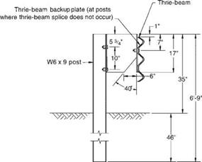
W6 x 9 steel or 6 in x 8 in wood M14 x 18 steel 6 ft-3 in

12-gage thrie-beam 34 in

Approximately 3 ft for a 20,000-pound school bus (56 mph, 15° impact angle)

Remarks: Modified thrie-beam was first installed in Rhode Island, Colorado, Nebraska, and Michigan as an experimental barrier. Since that time, it has been reclassified as an operational system, requiring virtually no repair for shallow-angle hits. This barrier can accommodate vehicles ranging in size from 1700-lb subcompacts to a 33,000-lb intercity bus,

FIGURE 6.19 Modified thrie-beam roadside barrier. Conversions: 1 in = 25.4 mm, 1 ft = 0.305 m. (From Roadside Design Guide, AASHTO, Washington, D. C., 2002 and 2006, with permission)

version shown in Fig. 6.21a is 90 in (2290 mm) high; also, it is sloped on both faces. It contains impacting tractor-trailers but has not completely eliminated rollovers. Successfully testing to TL-6 has been reported. The version shown in Fig. 6.21b is 64 in (1630 mm) high. Apparently effective, it is buttressed by an earth berm on the back side and topped with a W-beam barrier. Constant slope and vertical wall barriers have also been successfully tested (Art. 6.9.1).

The stone masonry wall system (Fig. 6.22), with a reinforced concrete core and a facing of stone and mortar, offers another aesthetic alternative for parks and similar applications. This barrier meets TL-3. Alternative systems with precast units are also available.

Water lifts, paddlewheels, and water mills in the world of Vitruvius

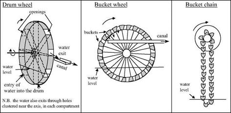
Vitruvius provides the oldest known description of a water lift powered by hydraulic force, or noria, and of a water mill. This description comes immediately after that of manual water lifts (drum wheel, bucket wheel: see Figure 6.20):

“Wheels on rivers are constructed upon the same principles as those just described (manual lift wheels). Round their circumference are fixed paddles (pinnae), which, when acted upon by the force of the current, drive the wheel round, receive the water in the buckets, and carry it to the top with the aid of treading; thus by the mere impulse of the stream supplying what is required.

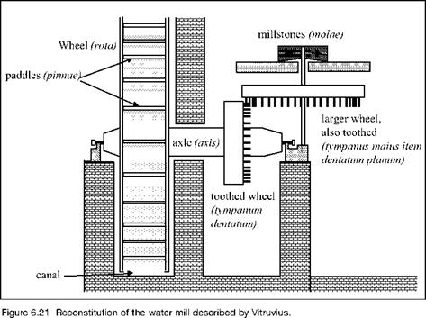
“Water mills (hydraletae) are turned on the same principle, and are in all respects similar, except that at one end of the axis they are provided with a drum-wheel, toothed and framed fast to the said axis; this being placed vertically on the edge turns round with the wheel. Corresponding with the drum-wheel a larger horizontal toothed wheel is placed, working on an axis whose upper head is in the form of a dovetail, and is inserted into the mill-stone. Thus the teeth of the drum-wheel which is made fast to the axis acting on the teeth of the horizon­tal wheel, produce the revolution of the mill-stones, and in the engine a suspended hopper supplying them with grain, in the same revolution the flour is produced.”[250]

Figure 6.21 is an attempt to reconstitute the devices described by Vitruvius. We

Water lifts, paddlewheels, and water mills in the world of Vitruvius

Figure 6.20 The manual water lifts described by Vitruvius, the possible origins of the noria and water mill. The lift height increases from left to right.

recall that he was a contemporary of Augustus (about 25 BC), and therefore came after the reign of Mithridate, though by only a few decades. He doesn’t enlighten us on the details of the innovation much better than did the Greek sources that we cited in Chapter 5. These details and their origins therefore remain somewhat obscure. However, two clues enable us to form at least a rough idea of how the devices operated.

Water lifts, paddlewheels, and water mills in the world of Vitruvius

The first clue is Vitruvius’ outline, the order in which he describes the different machines. He puts his description of the water mill in between those of the water lifts – as in Figure 6.20. He first describes the drumwheel, then the bucket wheel, and finally the bucket chain. All three machines are powered by human muscular force, and raise water to increasing heights in the order they are listed. It is after these descriptions that Vitruvius describes the paddle wheel powered by the force of the current and equipped with buckets to lift the water, and then finally the mill that turns a grinding stone using hydraulic force.

Vitruvius’ work then comes back to lifting machines, presenting two inventions of the 3rd century BC that we have already seen: the Archimedes screw or limagon, and the pump of Ctesibios.[251] Certain authors[252] believe it is possible that the order in which these machines are described, an order whose logic is not at all obvious, must correspond to a technical genealogy of these wheels. The manual bucket wheel could have been per­fected through the addition of paddles, so that it could be powered by the force of the current. In this case the paddle wheel could have been used to lift water (this is the noria, an invention destined to have a glorious future in the Orient), before it was real­ized that the rotation of the wheel could, through appropriate gearing, be used to turn a millstone. Other authors[253] propose that the vertical-axis mill (having a horizontal mill­stone) was invented first, since it does not require reduction gearing to turn the stone. Moreover, this mill appears in China at about the same time, as we see further on in Chapter 8.

A second clue as to the first use of the paddle wheel can be found a bit further on in the same book X of Vitruvius. There, he describes procedures “passed down to us from our ancestors” (which ones?) to measure travel distances over land or water; these would be “hodometers”. After describing the adaptation of the idea to chariots, Vitruvius then describes an analogous procedure for measuring the distance traversed through the water by boats. It is the paddle wheel that comprises the essential part of this instrument:

“In navigation, with very little change in the machinery (i. e. the hodometer for wheeled char­iots), the same thing may be done. An axis is fixed across the vessel, whose ends project beyond the sides, to which are attached wheels four feet in diameter, with paddles (pinnas) to them touching the water. [….]

“Thus, when the vessel is on its way, whether impelled by oars or by the wind, the paddles of the wheels, driving back the water which comes against them with violence, cause the wheels to revolve, whereby the axle is also turned round, and consequently with it the drum-wheel, whose tooth, in every revolution, acts on the tooth in the second wheel, and produces moder­ate revolutions thereof.”[254]

We know that on modern ships a common instrument for measuring the speed is a small paddle wheel. However the procedure described by Vitruvius appears curious to say the least, and it seems doubtful that its use was widespread.

Semirigid Systems

The box-beam (weak-post) system (Fig. 6.16) achieves its resistance through the com­bined flexural and tensile resistance of the box beam. Posts near the impact point are designed to break or tear away and distribute the impact force to adjacent posts. This system meets TL-3. The system is sensitive to mounting height and irregularities in terrain.

The blocked-out W-beam (strong-post) system (Fig. 6.17) is the most common barrier. The blockout or offset of the rail from the post minimizes vehicle snagging and reduces likelihood that a vehicle would vault over the barrier. The system is classified as TL-2 or TL-3, depending upon the type of blocks. As with all strong-post systems, resistance is developed by a combination of the tensile and flexural resistance of the rail and the flexural and shear strength of the post. Dynamic deflections are less than those of flexible systems. Bolt washers on the posts can be eliminated on this and other strong-post systems; they are not needed for strength, and it is desirable for the rail to break away as the post rotates downward. Strong-post systems tend to remain functional after moderate collisions, so that immediate repairs are not necessary.

The blocked-out thrie-beam (strong-post) system (Fig. 6.18) is similar to the pre­ceding system, but it has a deeper, stiffer, three-corrugation rail. This makes it less prone to damage during impact, allows higher rail mounting, and is better able to contain larger vehicles under some impact conditions. The system is classified as TL-2 or TL-3, depending upon the type of blocks.

The modified thrie-beam system (Fig. 6.19) has a steel blockout with a triangular notch cut from its web. This allows the lower part of the beam and the face of the spacer block to bend in during impact, causes the rail face to remain nearly vertical as the post is bent back, and reduces likelihood that a vehicle would roll over the barrier.

5-3

Подпись:УУАУАУА4

Soil Plate

Typical

AASHTO Designation

Подпись: 6 in x 6 in x 0.19 in steel tube Approximately 5 ft
Подпись: Beam Type:
Подпись: Maximum Dynamic Deflection

Semirigid SystemsPost Type: Post Spacing:

Semirigid Systems

FIGURE 6.17 Blocked-out W-beam (strong-post) roadside barrier. Conversions: 1 in = 25.4 mm, 1 ft = 0.305 m. (From Roadside Design Guide, AASHTO, Washington, D. C., 2002 and 2006, with permission)

Also, bolt washers have been eliminated on the posts, as discussed previously. The modifications have resulted in a TL-4 rating. Repair costs of either thrie-beam system should be considerably less than for other metal barrier systems, because damage tends to be slight in shallow-angle impacts. Also, it is considered easier to install and main­tain than a W-beam system with rub rail.

Semirigid Systems

FIGURE 6.18 Blocked-out thrie-beam (strong-post) roadside barrier. Conversions: 1 in = 25.4 mm, 1 ft = 0.305 m. (From Roadside Design Guide, AASHTO, Washington, D. C., 2002 and 2006, with permission)

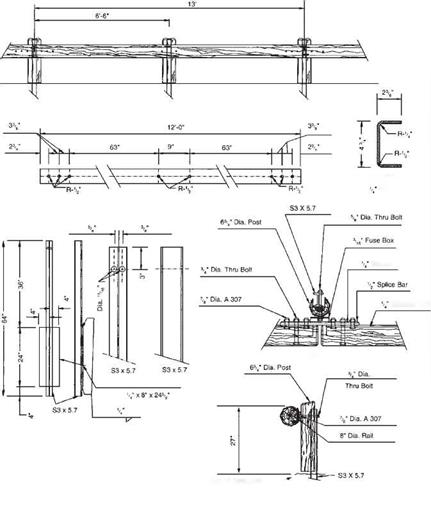
The steel-backed timber-rail system (Fig. 6.20) is an aesthetic alternative to conventional systems, often selected for use along park roads. It has been successfully tested to TL-3.

Compaction Factor

Almost all documents on SMA reviewed for the purposes of this book contain the compaction factor as a specified requirement. As in many other cases, the differ­ences between European and U. S. specifications are clear.

That factor has been defined differently in different countries. The differences are grounded in the different reference density used related to the bulk density of the layer achieved on the construction site. That is the source of the sharp differences in numerical values: from 94% (the United States.) to 98% (Norway). The description of two basic definitions of the compaction factor follows later on.

Mix design After construction End of service life

FIGURE 10.13 Change in the content of air voids in an SMA layer. (From Voskuilen, J. L.M., Proceedings of the 6th International Conference Durable and Safe Road Pavements, Kielce [Poland], 2000. With permission.)

10.6.2.1 Compaction Factor as a Quotient of Bulk Densities

In European practice, compaction factors based on a quotient of bulk densities have been commonly used. That quantity is calculated in percent according to the formula

c = Ps – -100%

Psl

where

c = compaction factor, %

ps = the bulk density of a specimen cut out of a pavement, g/cm3

psl = the bulk density of a specimen prepared of the same constituents and com-
pacted in laboratory conditions (so-called reference specimen), g/cm3

The most common requirement for the SMA compaction factor calculated accord­ing to this equation is c is at least 97%, though the requirement of c being no less than 98% can also been found.

A sine qua non for the correct calculation is taking into account the following assumptions:

• The SMA mixture used for preparing reference specimens compacted in a laboratory should come from the mixture being placed (e. g., from a truck just leaving the asphalt plant).

• Compaction conditions for reference specimens, specifically the tempera­ture and compaction, should be adequate to meet the real conditions pre­vailing on the construction site.

• The control specimens cut out of the pavement should not come from areas close to the edges or at the beginning or end of a working lot.

The German guidelines for compacting asphalt surfacing (M VA 2005) have included additional procedures and directions to facilitate control of the compaction process for difficult-to-compact mixtures. The compaction factor of an asphalt layer, denoted as k, is calculated according to the equation:

к =—P——— 100%

P

lab/

s (E=50)

where

p/ = the bulk density of a specimen cut out of a placed layer pslab(E=50) = the bulk density of a specimen prepared in a laboratory with the use of 50 strokes of a Marshall hammer on each side of a specimen

The bulk density of laboratory specimens is determined on material prepared with 2 x 50 strokes of a Marshall hammer. The compaction temperature should be appropriate for the applied binder. Due to various interpretation problems and mis­takes in the calculation of the index k, the new German guidelines (M VA 2005) have introduced an additional parameter—the compaction index K referring to the bulk density achieved on the construction site relative to the maximum density

K = ^ • 100%

P”

where

K = compaction index, %

psb = the bulk density of a specimen cut out of an executed layer

p" = the maximum analytical density of a given mixture

Having substituted the maximum density, the values of the compaction index will be higher than 94%. The method of using the quotient of two bulk densities for deter­mining the SMA compaction factor has been called out by the European standard EN 13108-20. Its clause C.3 stipulates that the reference density for indicating the compaction factor is the bulk density. The standard also provides that detailed condi­tions for preparing specimens and determining that density using EN 12697-5 and EN 12697-6 shall be declared.

Monte Carlo Simulation

6.1 Introduction

As uncertainty and reliability related issues are becoming more critical in en­gineering design and analysis, proper assessment of the probabilistic behavior of an engineering system is essential. The true distribution for the system response subject to parameter uncertainty should be derived, if possible. How­ever, owing to the complexity of physical systems and mathematical functions, derivation of the exact solution for the probabilistic characteristics of the system response is difficult, if not impossible. In such cases, Monte Carlo simulation is a viable tool to provide numerical estimations of the stochastic features of the system response.

Simulation is a process of replicating the real world based on a set of assump­tions and conceived models of reality (Ang and Tang, 1984, pp. 274-332). Since the purpose of a simulation model is to duplicate reality, it is an effective tool for evaluating the effects of different designs on a system’s performance. Monte Carlo simulation is a numerical procedure to reproduce random variables that preserve the specified distributional properties. In Monte Carlo simulation, the system response of interest is repeatedly measured under various system pa­rameter sets generated from known or assumed probabilistic laws. It offers a practical approach to uncertainty analysis because the random behavior of the system response can be duplicated probabilistically.

Two major concerns in practical applications of Monte Carlo simulation in uncertainty and reliability analyses are (1) the requirement of a large number of computations for generating random variates and (2) the presence ofcorrelation among stochastic basic parameters. However, as computing power increases, the concern with the computation cost diminishes, and Monte Carlo simulations are becoming more practical and viable for uncertainty analyses. In fact, Beck (1985) notes that “when the computing power is available, there can, in general, be no strong argument against the use of Monte Carlo simulation.”

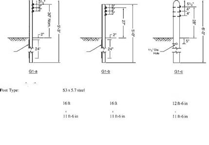
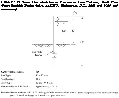
The three-cable system (Fig. 6.13) has been successfully tested to TL-3. It is made up of three steel cables mounted on weak posts. The cable barrier redirects impacting vehicles after the cable deflects and develops tension, with the posts offering little direct resistance. Several states allow a backslope as steep as 1:2 behind the rail. If the barrier is placed on the inside of a curve, additional deflection will occur before tension develops in the cable, and thus it may be desirable to limit the radius. New York installs the barrier having S3 X 5.7 (S75 X 8.5) steel posts for radii of 721.5 ft (220 m) or more with the standard 16-ft (4.9-m) post spacing, and for radii of 442.5 ft (135 m)

TABLE 6.2 Classification of Roadside Barriers and Approved Test Levels

Barrier system Test level

Flexible systems

Three-strand cable (weak-post) TL-3

W-beam (weak-post) TL-2

Modified W-beam (weak-post) TL-3

Ironwood aesthetic barrier TL-3

Semirigid systems

Box-beam (weak-post) TL-3

Blocked-out W-beam (strong-post)

Steel or wood post with wood TL-3

or plastic block

Steel post with steel block TL-2

Blocked-out thrie-beam (strong-post)

Wood or steel post with wood TL-3

or plastic block

Modified thrie-beam (strong-post) TL-4

Merritt Parkway aesthetic guardrail TL-3

Steel-backed timber guardrail TL-3

Rigid systems (concrete and masonry)

New Jersey concrete safety-shape

32 in (810 mm) tall TL-4

42 in (1070 mm) tall TL-5

F-shape barrier

32 in (810 mm) TL-4

42 in (1070 mm) TL-5

Vertical concrete barrier

32 in (810 mm) TL-4

42 in (1070 mm) TL-5

Single-slope barrier

32 in (810 mm) TL-4

42 in (1070 mm) TL-5

Ontario tall-wall median barrier TL-5

Stone masonry wall/precast TL-3

masonry wall

Source: From Roadside Design Guide, AASHTO,

Washington, D. C., 2002 and 2006, with permission.

or more with a 12-ft (3.7-m) post spacing. Advantages of the three-cable barrier include low initial cost, effective vehicle containment and redirection over a wide range of vehicle sizes and installation conditions, low deceleration forces, and func­tionality in snow or sand areas because the open design prevents drifting. Disadvantages include the long lengths that are nonfunctional and must be repaired after an impact, the clear area behind the barrier needed to accommodate the design deflection distance, reduced effectiveness on the inside of curves, and sensitivity to correct height installation and maintenance.

The W-beam (weak-post) system (Fig. 6.14) behaves much like a cable system, but the deflection is much less. Thus, the required clear area behind the barrier is less. The

The three-cable system (Fig. 6.13) has been successfully tested to TL-3. It is made up of three steel cables mounted on weak posts. The cable barrier redirects impacting vehicles after the cable deflects and develops tension, with the posts offering little direct resistance. Several states allow a backslope as steep as 1:2 behind the rail. If the barrier is placed on the inside of a curve, additional deflection will occur before tension develops in the cable, and thus it may be desirable to limit the radius. New York installs the barrier having S3 X 5.7 (S75 X 8.5) steel posts for radii of 721.5 ft (220 m) or more with the standard 16-ft (4.9-m) post spacing, and for radii of 442.5 ft (135 m)

Soil Plate Typical"


Soil Plate Typical


A ASHTO Designation:


Gl-a


The three-cable system (Fig. 6.13) has been successfully tested to TL-3. It is made up of three steel cables mounted on weak posts. The cable barrier redirects impacting vehicles after the cable deflects and develops tension, with the posts offering little direct resistance. Several states allow a backslope as steep as 1:2 behind the rail. If the barrier is placed on the inside of a curve, additional deflection will occur before tension develops in the cable, and thus it may be desirable to limit the radius. New York installs the barrier having S3 X 5.7 (S75 X 8.5) steel posts for radii of 721.5 ft (220 m) or more with the standard 16-ft (4.9-m) post spacing, and for radii of 442.5 ft (135 m)

The three-cable system (Fig. 6.13) has been successfully tested to TL-3. It is made up of three steel cables mounted on weak posts. The cable barrier redirects impacting vehicles after the cable deflects and develops tension, with the posts offering little direct resistance. Several states allow a backslope as steep as 1:2 behind the rail. If the barrier is placed on the inside of a curve, additional deflection will occur before tension develops in the cable, and thus it may be desirable to limit the radius. New York installs the barrier having S3 X 5.7 (S75 X 8.5) steel posts for radii of 721.5 ft (220 m) or more with the standard 16-ft (4.9-m) post spacing, and for radii of 442.5 ft (135 m)

Post Spacing:

Подпись:Подпись: 7 -in-dia. steel cablesBeam Type:

Maximum Dynamic Deflection:

Подпись:
Remarks: For shallow angle impacts, barrier damage is usually limited to several posts, which must be replaced. Cable damage is rare except in severe crashes. A crashworthy end terminal is critical in each of the cable systems, both to provide adequate anchorage to develop full tensile strength in the cable and to minimize vehicle decelera­tions for impacts on either end of an installation.

The three-cable system (Fig. 6.13) has been successfully tested to TL-3. It is made up of three steel cables mounted on weak posts. The cable barrier redirects impacting vehicles after the cable deflects and develops tension, with the posts offering little direct resistance. Several states allow a backslope as steep as 1:2 behind the rail. If the barrier is placed on the inside of a curve, additional deflection will occur before tension develops in the cable, and thus it may be desirable to limit the radius. New York installs the barrier having S3 X 5.7 (S75 X 8.5) steel posts for radii of 721.5 ft (220 m) or more with the standard 16-ft (4.9-m) post spacing, and for radii of 442.5 ft (135 m)system meets Tl-2 or TL-3, depending upon details. The system is sensitive to mounting height and irregularities in terrain.

The Ironwood barrier shown in Fig. 6.15 is a proprietary weak-post system that meets TL-3. It has a composite rail that consists of round-wood sections with steel channels embedded on the backside. The steel support posts are faced with timber posts above the ground line. Thus, the system presents an all-timber appearance. Crashworthy terminal designs have not been developed but the ends may be anchored in a backslope or flared to the edge of the clear zone.

ELEVATION

CHANNEL RAIL

PLATE

CHANNEL RAIL ELEVATION

Washer

Channel Rail

PLAN

STEEL POST

Edge of Pavement or^"’ Groundline at Face of Rail

SIDE

Grout Sealers

Sealing grouts will make grout joints easier to clean and more resistant to water penetration and staining. When water penetrates grout joints, it makes them susceptible to mold and bacterial growth. Even grouts containing mil – dewcides can eventually become moldy. Be­sides sealing grouts in wet areas, the key to mold-free grout is maintenance. Bathrooms should be kept dry by using exhaust fans, and grout joints should be cleaned regularly We do not recommend the commercially avail­able grouts enhanced with additives. We have found the following sealing methods to be generally well-tolerated by chemically sensi­tive individuals:

• AFM Safecoat Grout Sealer: A clear, moisture-resistant sealer for porous tile grout to help prevent staining

• AFM Safecoat Safe Seal: An odorless, zero-VOC, water-based, low-gloss sealer for highly porous surfaces, it can be di­luted in a 50:50 ratio with water and then mixed into the dry grout to form an inte­gral grout sealer

Stone

While stone is generally a healthful and beau­tiful choice for flooring and decorative ac­cents, it raises the same concerns about proper installation as ceramic tile does. The specifica­tions we have outlined for ceramic tile also ap­ply to stone.

We have tested several stone products for radiation and radon content and found a range of readings from very low to high levels. Al­though uranium content in construction ma­terials is not usually considered to be a serious concern, Johns experience, as shared in Case Study 9.2, leads us to conclude that stone can contribute significantly to ambient radon lev­els in a home. We recommend that stone, es­pecially granite, be screened for radon prior to installation, even though the Granite Institute has issued a scientific report concluding that granite countertops do not emit radioactivity into the home. Tests are easily performed as described in Division 13.

Stone Installation

Refer to our discussion of the thickset method in the section on tile installation above and to the section on stone countertops in Divi­sion 6.

Sealers for Stone

Tire following finishes are free of petroleum – based solvents and can be used for most stone flooring, shelving, and countertops:

• AFM Safecoat MexeSeal: A durable sealer providing water and oil repellency, applied over AFM Safecoat Paver Seal.003, an un­dersealer for porous materials

• Lithofin: Stone sealers

• Livos Meldos Hard Oil and Livos Bilo Floor Wax: A penetrating oil sealer and a clear, mar-resistant finish wax respec­tively; can be odorous when first applied and should be carefully tested prior to use by a chemically sensitive individual

• Naturel Cleaner and Sealer: Water – soluble flakes that clean, protect, and fin­ish stone surfaces

Flooring

Flooring Installation Over Concrete

Flooring materials such as wood, carpeting, and resilient flooring are often laid over a con­crete slab. If the concrete slab has a high mois­ture content resulting from inadequate cur­ing time or from a high water table, then the perfect conditions exist for mold growth: an environment that is dark, moist, still, and nu­tritious. Flooring manufacturers publish rec­ommended maximum vapor-emissions levels for installations of their products over con­crete slab. When these levels are exceeded, the warranty is void. Unfortunately, slabs are rarely measured for vapor emissions.

Where finished flooring, especially wood flooring, is laid over concrete slab with radi­ant heat tubing in it, we have encountered an additional problem. A slab that appears to be fully cured will have unacceptably high vapor emissions when the heat is first turned on. Often the heat is turned on only after floor fin­ishes have been applied and the construction is completed.

We consider these to be important quality control issues and suggest the following speci­fications: [16] [17]

CASE STUDY 9.2

MORE SIDING OPTIONS

Подпись: The exterior of the house can be closed in rapidly with sheets of textured plywood or OSB. [Photo by Don Charles Blom] Подпись:MORE SIDING OPTIONS

In addition to vinyl siding, there are three more exterior finishes to consider if you’re interested in affordability, low maintenance, and attractive appearance:

COMPOSITE WOOD. These planks are made the same way as OSB sheathing panels, but they look like solid – wood clapboards or horizontal lap siding when installed. This siding comes with a factory-applied primer coat, and it needs to be painted after installation. Composite-wood planks don’t split, crack, or warp like solid-wood siding does, but they may not be a wise choice in extremely wet climates. These clapboards nail on walls much like cement fiber boards.

STUCCO. Two types of stucco finishes can be applied to house exteriors. Lightweight acrylic-type stucco treatments are available for application over specially prepared foam insulation board. Old-fashioned Portland cement-based stucco can be applied to masonry walls and to wire or stucco lath that’s been fastened to wall sheathing or directly to studs. It’s best to hire experienced professional
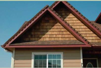
crews to do these treatments. In hot, sunny climates, stucco stands up better than most other siding treatments. SHINGLES. Many houses, especially in coastal areas, have cedar shingles on their exterior walls. Sometimes in Oregon we will shingle the gable ends of a house just to give it a distinctive look. I think it is safe to say that if you can nail composite shingles on a roof you can learn how to nail wood shingles on a wall. You can also buy cement fiber shingle panels that make it easier to cover a gable end or even an entire house

When you use shingles, start by covering the exterior walls with OSB panels and a good housewrap. The courses of shingles can be laid out with a story pole. The first course is doubled just as if they were roof shingles. Check with a local contractor to make sure you are using the right fasteners to nail each shingle in place. In coastal areas you will want to use a nail that doesn’t rust easily.

PLYWOOD OR OSB SIDING. I have been sheathing houses with plywood panels for years. In the past, some of these products didn’t hold up well over time. In wet

Подпись: Windows can be trimmed in a number of ways. Here we are using 1x3s to trim and seal this window. [Photo by Don Charles Blom] Подпись:MORE SIDING OPTIONSclimates, the plywood delaminated. In dry climates, the surface cracked easily and paint peeled off. Houses began to look like the prairie house I lived in during the 1930s.
Pretty shabby.

Texture 1-11, orT1-11, plywood panels come in different sizes and textures. The standard size of these plywood sheets is 4 ft. by 8 ft., with 1/4-in.-wide grooves cut into the face every 4 in., 8 in., or 12 in. These sheets can be purchased with a tex­tured face without grooves and even come in 9-ft. and 10-ft. lengths. These longer lengths allow you to sheathe both an 8-ft. wall and the rim joist with one piece. The same patterns and sizes are available as an OSB product. I actually prefer the OSB panels, called Smartside®, because they come paint-primed on the front side.

I have been using these panels in wet, coastal Oregon on some of the small houses we have built. You can rapidly close in the exterior walls with this material. I always prime the backside and edges before installation.

Installation is straightforward. The panels can usually be nailed directly to the studs once the housewrap is on and the windows are in place. Some people square up the framed
walls on the floor and nail on sheathing before standing the walls upright.

The siding needs to extend down over the foundation 1 in.

I begin by snapping a chalkline 1 in. below the bottom sill plate all the way around the house. Start from the corner that has a 4 ft. o. c. stud layout. Use a level to make sure this first panel is nailed on plumb and level directly on the chalkline. Get this first one right and all the following panels will install easily. I like to nail off the sheets with 7d or 8d galvanized ringshank nails. Nail each panel every 6 in. around the perim­eter and every 12 in. out in the field.

Make your measurements and cuts within 1/8 in. to 1/4 in. around windows, doors, electrical outlets, or dryer vent. Before nailing these panels in place, run a bead of good exte­rior caulk around the openings and under the sheathing. Once the sheets are nailed in place, fill any gap between the panel and the window or door frame with caulk to help prevent wa­ter from entering at these points.

Trim forT1-11 or OSB sheeting is rather simple. Use roughsawn 1x4s to cover the outside corners and full 1-in.-sq. stock ripped from a 2×4 on the inside corners. Use frieze blocks between rafters when they are exposed, and 1x3s or 1x4s to trim around the windows and doors.

Подпись: Take care when cutting cement- fiber boards. They no longer have asbestos in them, but they do have silica. You definitely don't want to inhale that stuff, so get yourself a pair of electric shears that won't create dust (see Resources on p. 279)You can also buy circular saws that have dust catchers. These saws can be hooked to a shop vacuum that will catch almost all of the dust.

Paddle wheels and water mills in the Roman world, the beginnings of industrial use of water

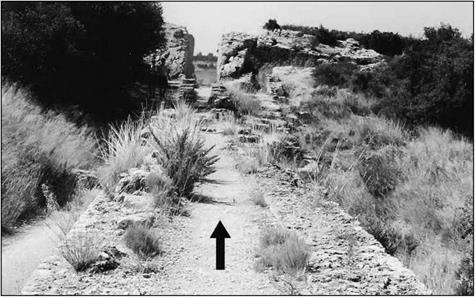
In the provincial countryside some ten kilometers from Arles in the direction of Saint-Remy-de-Provence, a hiker can come upon the remains of Roman aqueducts on arches. These remains are even indicated by a sign. Looking at the remains closely, the tourist can easily see that there are in fact two parallel aqueducts, side by side. If the hiker follows the path alongside these aqueducts, he or she comes upon a deep notch cut in a rocky outcrop. The canal of the left aqueduct passes through this notch (Figure 6.19).

After passing through this notch, our hiker then comes out at the top of an escarp­ment, 20 meters high along a length of 60 meters, beyond and below which is a broad plain with no visible trace of the aqueduct. On the slope one can recognize the ruins of walls and structures in the form of stairways (Figure 6.22). These ruins were identified in 1935 by Fernand Benoit as those of a Roman hydraulic flour mill, the mill of Barbegal, the very first of this kind known to us.

Paddle wheels and water mills in the Roman world, the beginnings of industrial use of water

Figure 6.19 Barbegal: the remains of the canal of the left-hand aqueduct, and the notch in the rocky outcrop that marks its end (the right-hand aqueduct, though it cannot be seen in this photo, turns sharply before the rocky outcrop and continues its route toward Arles) (photo by the author).

In Chapter 5 we mentioned the appearance of the water mill in Asia. This was only weakly suggested by an allusion of Strabo to the mill in the palace of Mithridate, king of Pontus, conquered by the Romans in the middle of the 1st century BC. The appear­ance of this device marked a major step in the history of technology, but passed almost unnoticed. With the Romans, the first written evidence of a mill is found in book X of Vitruvius’ work. Let us examine how Vitruvius describes the new technology to get a clearer idea of how it appeared.