Category Hydrosystems Engineering Reliability Assessment and Risk Analysis

Generation of Random Numbers

The most commonly used techniques to generate a sequence of pseudorandom numbers are those that apply some form of recursive computation. In principle, such recursive formulas are based on calculating the residuals modulo of some integers of a linear transformation. The process of producing a random number sequence is completely deterministic. However, the generated sequence would appear to be uniformly distributed and independent.

Congruential methods for generating n random numbers are based on the fun­damental congruence relationship, which can be expressed as (Lehmer, 1951)

Xi+i = {aXi + c}(mod m) i = 1,2,…, n (6.1)

in which a is the multiplier, c is the increment, and m is an integer-valued modulus. The modulo notation (mod m) in Eq. (6.1) represents that

Xi+1 = aXi + c – mIi (6.2)

with Ii = [(aXi + c)/m] denoting the largest positive integer value in (aXi + c)/m. In other words, Xi+1 determined by Eq. (6.1) is the residual resulting from (aXi + c)/m. Therefore, the values of the number sequence generated by Eq. (6.1) would satisfy Xi < m, for all i = 1, 2,…, n. Random number gener­ators that produce a number sequence according to Eq. (6.1) are called mixed congruential generators.

Applying Eq. (6.1) to generate a random number sequence requires the spec­ification of a, c, and m, along with X0, called the seed. Once the sequence of random number Xs are generated, the random number from the unit interval ui є [0,1] can be obtained as

Ui = — i = 1, 2,…, n (6.3)

m

It should be pointed out that the process of generating uniform random numbers is the building block in Monte Carlo simulation.

Owing to the deterministic nature of the number generation, it is clear that the number sequence produced by Eq. (6.1) is periodic, which will repeat itself in, at most, m steps. This implies that the sequence would contain, at most, m distinct numbers and will have a maximum period of length m — 1 be­yond which the sequence will get into a loop. For example, consider Xi+1 = 2Xi + 3(mod m = 5), with X0 = 3; the number sequence generated would be 4,1,0, 3,4,1,0,….

From the practical application viewpoint, it is desirable that the generated number sequence have a very long periodicity to ensure that sufficiently large amounts of distinct numbers are produced before the cycle occurs. Therefore, one would choose the value ofthe modulus m to be as large as possible. However, the length of the periodicity in a sequence also depends on the values of mul­tiplier a and increment c. Knuth (1981) derived three conditions under which a sequence from Eq. (6.1) has a full period m. Based on the three conditions of Knuth (1981), Rubinstein (1981) showed that for a computer with a binary digit system, using m = 2в, with в being the word length of the computer, along with an odd number for parameter c and a = 2r + 1, r > 2 would produce a full period sequence. The literature (Hull and Dobell, 1964; MacLaren and Marsagalia, 1965; Olmstead, 1946) indicates that good statistical results can be achieved by using m = 235, a = 27 + 1, and c = 1. Table 6.2 lists suggested values for the parameters in Eq. (6.1) for different computers.

TABLE 6.2 Suggested Values for Parameters in Congruential Methods

Constants for portable random number generators

Overflow at

m

a

c

Overflow at

m

a

c

220

6075

106

1283

228

117128

1277

24749

221

7875

211

1663

312500

741

66037

222

7875

421

1663

121500

2041

25673

223

11979

430

2531

229

120050

2311

25367

6655

936

1399

214326

1807

45289

6075

1366

1283

244944

1597

51749

224

53125

171

11213

233280

1861

49297

11979

859

2531

175000

2661

36979

29282

419

6173

121500

4081

25673

14406

967

3041

145800

3661

30809

225

134456

141

28411

230

139968

3877

29573

31104

625

6571

214326

3613

45289

14000

1741

2957

714025

1366

150889

12960

1741

2731

231

134456

8121

28411

21870

1291

4621

243000

4561

51349

139968

205

29573

259200

7141

54773

226

81000

421

17117

232

233280

9301

49297

29282

1255

6173

714025

4096

150889

134456

281

27411

233

1771875

2416

374441

227

86463

1093

18257

234

510300

17221

107839

259200

421

54773

312500

36261

66037

116640

1021

24631

235

217728

84589

45989

121500

1021

25673

SOURCE: After Press et al. (1989).

A second commonly used generator is called the multiplicative generator-.

Xi+1 = {aXi }(mod m) i = 1,2,…, n (6.4)

which is a special case of the mixed generator with c = 0. Knuth (1981) showed that a maximal period can be achieved for the multiplicative generator in a binary computer system when m = 2e and a = 8r ± 3, with r being any positive integer.

Another type of generator is called the additive congruential generator having the recursive relationship as

Xi+1 = {Xi + Xi-t }(mod m) t = 1,2,…, i – 1 (6.5)

As can be seen, the random numbers generated by the additive congruen – tial generator depend on more than one of its preceding values. When t = 1, Eq. (6.5) would generate a sequence of Fibonacci numbers, which are not satis­factorily random. However, the statistical properties improve as t gets larger.

In summary, to ensure that a sequence of random numbers generated by the congruential methods would have satisfactory statistical properties, Knuth (1981) recommended the following principles to choose the parameters a, c, m, and X0. [9]

Copyright © 2006 by The McGraw-Hill Companies, Inc. Click here for terms of use

As noted previously, the accuracy of the model output statistics and probabil­ity distribution (e. g., probability that a specified safety level will be exceeded) obtained from Monte Carlo simulation is a function of the number of simu­lations performed. For models or problems with a large number of uncertain basic variables and for which low probabilities (<0.1) are of interest, tens of thousands of simulations may be required. Rules for determining the number of simulations required for convergence are not available, and thus replication of the Monte Carlo simulation runs for a given number of simulations is the only way to check convergence (Melching, 1995). Cheng et al. (1982) considered the convergence characteristics of Monte Carlo simulation for a simple case of Z = X3X4 – (X1 + X2), where the distributions and statistics of the variables are listed in Table 6.1. They found that failure probabilities (i. e., probability of Z < 0) down to 0.0025 could be estimated reliably with 32,000 simulations, failure probabilities down to 0.015 could be estimated reliably with 8000 sim­ulations, and failure probabilities down to 0.2 could be estimated reliably with 1000 simulations.

Problems involving more complex system functions Z and more basic vari­ables may require more simulations to obtain similar accuracy. For example, Melching (1992) found that 1000 simulations were adequate to estimate the mean, standard deviation, and quantiles above 0.2 for an application of the HEC-1 (U. S. Army Corps of Engineers, 1990) and RORB (Laurenson and Mein, 1985) rainfall-runoff models and that 10,000 simulations were needed to ac­curately estimate quantiles between 0.01 and 0.2. Brown and Barnwell (1987) reported that for the QUAL2E multiple-constituent (dissolved oxygen, nitrogen cycle, algae, etc.) steady-state surface water-quality model, 2000 simulations were required to obtain accurate estimates of the output standard deviation. With the computational speed of today’s computers, making even 10,000 runs is not prohibitive for simpler models. However, increased computational speed has made possible the use of computational fluid dynamics codes in three di­mensions for hydrosystems design work. When such codes are applied, the variance-reduction techniques described in Sec. 6.7 may be preferred to Monte Carlo simulation.

This chapter focuses on the basic principles and applications of Monte Carlo simulations in the reliability analysis of hydrosystems engineering problems. Section 6.2 describes some basic concepts of generating random numbers, fol­lowed by discussions on the classifications of algorithms for a generation of ran­dom variates in Sec. 6.3. Algorithms for generating univariate random numbers

TABLE 6.1 Basic Variable Statistics and Distributions for Evaluation of Monte Carlo Simulation of Convergence

Variable

Mean value

Coefficient of variation

Distribution function

X1

0.5

0.2

Uniform

X 2

1.5

0.4

Uniform

X 3

1.0

0.005

Lognormal

X 4

1.5

0.1

Lognormal

SOURCE: After Cheng et al. (1982).

are described in Sec. 6.4 for several commonly used distribution functions. In Sec. 6.5, attention is given to algorithms that generate multivariate ran­dom numbers. As reliability assessment involves mathematical integration, Sec. 6.6 describes several Monte Carlo simulation techniques for reliability evaluation. Given that Monte Carlo simulations, in essence, are sampling tech­niques, they provide only estimations, which inevitably are subject to certain degrees of errors. To improve the accuracy of the Monte Carlo estimation while reducing excessive computational time, several variance-reduction techniques are discussed in Sec. 6.7. Finally, resampling techniques are described in Sec. 6.8, which allow for assessment of the uncertainty of the quantity of interest based on the available random data without having to make assumptions about the underlying probabilistic structures.

Monte Carlo Simulation

6.1 Introduction

As uncertainty and reliability related issues are becoming more critical in en­gineering design and analysis, proper assessment of the probabilistic behavior of an engineering system is essential. The true distribution for the system response subject to parameter uncertainty should be derived, if possible. How­ever, owing to the complexity of physical systems and mathematical functions, derivation of the exact solution for the probabilistic characteristics of the system response is difficult, if not impossible. In such cases, Monte Carlo simulation is a viable tool to provide numerical estimations of the stochastic features of the system response.

Simulation is a process of replicating the real world based on a set of assump­tions and conceived models of reality (Ang and Tang, 1984, pp. 274-332). Since the purpose of a simulation model is to duplicate reality, it is an effective tool for evaluating the effects of different designs on a system’s performance. Monte Carlo simulation is a numerical procedure to reproduce random variables that preserve the specified distributional properties. In Monte Carlo simulation, the system response of interest is repeatedly measured under various system pa­rameter sets generated from known or assumed probabilistic laws. It offers a practical approach to uncertainty analysis because the random behavior of the system response can be duplicated probabilistically.

Two major concerns in practical applications of Monte Carlo simulation in uncertainty and reliability analyses are (1) the requirement of a large number of computations for generating random variates and (2) the presence ofcorrelation among stochastic basic parameters. However, as computing power increases, the concern with the computation cost diminishes, and Monte Carlo simulations are becoming more practical and viable for uncertainty analyses. In fact, Beck (1985) notes that “when the computing power is available, there can, in general, be no strong argument against the use of Monte Carlo simulation.”

Determinations of availability and unavailability

Determination of the availability or unavailability of a system requires a full accounting ofthe failure and repair processes. The basic elements that describe such processes are the failure density function ft (t) and the repair density func­tion gt (t). In this section computation of the availability of a single component or system is described under the condition of an ideal supportability. That is, the availability, strictly speaking, is the inherent availability. Discussions of the subject matter for a complex system are given in Chap. 7.

Consider a specified time interval (0, t], and assume that the system is ini­tially in an operating condition at time zero. Therefore, at any given time in­stance t, the system is in an operating state if the number of failures and repairs w(0, t) are equal, whereas the system is in a failed state if the number of failures exceeds the number of repairs by one. Let NF (t) and Nr (t) be the random vari­ables representing the numbers of failures and repairs in time interval (0, t], respectively. The state of the system at time instance t, failed or operating, can be indicated by a new variable I (t) defined as

I (t) = Nf (t) – Nr(t) (5.45)

Note that I(t) also is a random variable. As described earlier, the indicator variable I (t) is binary by nature, that is,

Подпись: I(t)1 if system is in a failed state

0 otherwise

Recall that the unavailability is the probability that a system is in the failed state, given that the system was initially operational at time zero. Hence the unavailability of a system is the probability that the indicator variable I (t) takes the value of 1, which is equal to the expected value of I (t). Accordingly,

U(t) = E [I (t)] = E [Nf (t)] – E [Nr(t)] = W(0, t) – Г(0, t) (5.46)

indicating that the unavailability is equal to the expected number of failures W(0, t) minus the expected number of repairs Г(0, t) in time interval (0, t]. The values of W(0, t) and Г(0, t) can be computed by Eqs. (5.43) and (5.44), respectively.

To compute W(0, t) and Г(0, t), knowledge of the unconditional failure in­tensity w(t) and the unconditional repair intensity y(t) is required. The un­conditional failure intensity can be derived by the total probability theorem as

w(t) = ft(t) +( y(t) ft(t – r) dr (5.47)

0

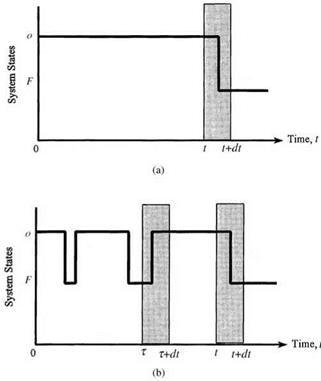
in which, on the right-hand side, the first term, ft (t), is for the case that the probability of failure is at time t, given that the system has survived up to time t; the second term accounts for the case that the system is repaired at time r < t and later fails at time t. This is shown in Fig. 5.18.

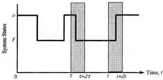
For the unconditional repair intensity y (t) one would need only to consider one possible case, as shown in Fig. 5.19. That is, the system is in an operating state at time t given that the system is operational initially and is in a failed state at time r < t. The probability that this condition occurs is

Y(t) = [ w(r)g(t – r) dr (5.48)

0

Determinations of availability and unavailability

Determinations of availability and unavailability

Figure 5.18 Two different cases for a system to be in a failed state during (t, dt]: (a) the system has been operational up to time t and failed during (t, t + dt), given that it was good at t = 0 and no repair has been done during (0, t); (b) the system has been operational up to time tand failed during (t, t + dt), given that it was good at t = 0 and was repaired at t = т. (After Henley and Kumamoto, 1981.)

Determinations of availability and unavailability

Note that given the failure density ft(t) and the repair density gt(t), the un­conditional failure intensity w(t) and the unconditional repair intensity y(t) are related to one another in an implicit fashion, as shown in Eqs. (5.47) and (5.48). Hence the calculations of w(t) and y (t) are solved by iterative numerical integration. Analytically, the Laplace transform technique can be applied to derive w(t) and y(t) owing to the convolution nature of the two integrals.

Based on the unavailability and unconditional failure intensity, the condi­tional failure intensity g(t) can be computed as

w(t)

1 – U (t)


w(t)

At)


g(t)


(5.49)


which is analogous to Eq. (5.3). For the repair process, the conditional repair intensity p(t), unconditional repair intensity y(t), and unavailability are re­lated as

p «> = ш (550)

The general relationships among the various parameters in the failure and repair processes are summarized in Table 5.4.

TABLE 5.4 Relationship among Parameters in Time-to-Failure Analysis

Repairable systems

Nonrepairable systems

General relations

A(t) + U (t) = 1

A(t) + U (t) = 1

A(t) > ps(t)

A(t) = ps(t)

U(t) < pf (t)

U(t) = pf (t)

w(t) = ft(t) + f ft(t – r)y(t) dr

w(t) = ft (t)

Y(t) = Jgt(t – r)w(r) dr

Y(t) = 0

W(t1, t2) = Jw(r)dr

W(t1, t2) = ps(t2) – ps(tx)

r(t1, t2) = f Y(r)dr

r(t1, t2) = 0

U(t) = W(0, t) – Г(0, t)

U(t) = pf (t)

!i(t) = w(t)/A(t)

h(t) = ft (t)/ps(t)

p (t) = y (t)/U (t)

r(t) = 0

Stationary values

MTBF = MTBR = MTTF + MTTR

MTBF = MTBR = to

0 < A(to), U(to) < 1

A(to) = 0, U(to) = 1

0 < w(to), y(to) < to

w(to) = 0, y(to) = 0

w(to) = y (to)

w(to) = y (to) = 0

W(0, to) = Г(0, to) = to

Remarks

W(0, to) = 1, Г(0, to) = 0

w(t) = Mt), Y(t) = p(t)

w(t) = Mt), Y(t) = p(t) = 0

Mt) = h(t), p(t) = r(t)

p,(t) = h(t), p(t) = r (t) = 0

w(t) = ft(t), y(t) = gt(t)

w(t) = ft(t), y(t) = gt(t) = 0

SOURCE : After Henley and Kumamoto (1981).

Example 5.12 For a given failure density function ft(t) and repair density function gt(t), solve for the unconditional failure intensity w(t) and the unconditional repair intensity y(t) by the Laplace transform technique.

Solution Note that the integrations in Eqs. (5.47) and (5.48) are in fact convolutions of two functions. According to the properties of the Laplace transform described in Appendix 5A, the Laplace transforms of Eqs. (5.47) and (5.48) result in the following two equations, respectively:

L[w(t)] = L[ ft(t)] + L[y(t)] x L[ ft(t)] (5.51a)

L[y(t)] = L[w(t)] x L[gt(t)] (5.51b)

Determinations of availability and unavailability Подпись: (5.52a) (5.52b)

in which L(-) is the Laplace transform operator. Solving Eqs. (5.51a) and (5.51b) simultaneously, one has

To derive w(t) and y(t), the inverse transform can be applied to Eqs. (5.52a) and (5.52b), and the results are

Подпись: L [ ft (t)] 1 (5.53a) 1 - L[ ft(t)] x L[gt(t)]  L[ ft(t)] x L[gt(t)] 1 1 - L[ ft(t)] x L[gt(t)] J (5.53b) Подпись: w(t) = L 1 Y (t) = L-1and

Example 5.13 (Constant failure rate and repair rate) Consider that the failure den­sity function ft(t) and the repair density function gt (t) are both exponential distribu­tions given as

ft(t) = Xe Xt for X > 0, t > 0

gt(t) = ne—qt for n > 0, t > 0

Derive the expressions for their availability and unavailability.

Solution The Laplace transform of the exponential failure density ft(t) is

/•TO /»ТО X

L[ ft(t)] = e-st ft(t) dt = X e-(s+X)t dt = ——————

Л J0 X +s

Determinations of availability and unavailability Подпись: 1 s Determinations of availability and unavailability

Similarly, L[gt(t)] = n/(n + s). Substituting L[ ft(t)] and L[gt(t)] into Eqs. (5.52a) and (5.52b), one has

Подпись: L [Y(t)](Л _X^( 1

X + n s f X + n s + X + n )

Determinations of availability and unavailability

Taking the inverse transform for the preceding two equations, the results are

The availability A(t) then is

Подпись: (5.59)A(t) = 1 – U(t) = -^ + —e-(k+n)t к + n к + n

As the time approaches infinity (t ^ те), the system reaches its stationary condition. Then the stationary availability А(те) and unavailability U(те), are

А(те) =

n

1/k

MTTF

(5.60)

к + n

1/k + 1/n

= MTTF + MTTR

U (те) =

к

1/n

MTTR

(5.61)

к + n

1/k + 1/n

MTTF + MTTR

Other properties for a system with constant failure and repair rates are summarized in Table 5.5. Results obtained in this example also can be derived based on the Markov analysis (Henley and Kumamoto, 1981; Ang and Tang, 1984).

Strictly speaking, the preceding expressions for the availability are the inherent availability under the condition of an ideal supportability with which the mean time to support (MTTS) is zero. In the case that the failed system requires some time to respond and prepare before the repair task is undertaken, the actual availability is

Подпись: А(те) =Подпись: (5.62)MTTF

MTTF + MTTR + MTTS which, as compared with Eq. (5.60), is less than the inherent availability.

Repairable systems

Nonrepairable systems

Failure process

h(t) = X

h(t) = X

Ps (t) = e-Xt

Ps(t) = e-Xt

Pf (t) = 1 – e-Xt

Pf (t) = 1 – e-Xt

ft (t) = Xe-lt

ft (t) = Xe-Xt

MTTF = 1/X

MTTF = 1/X

Repair process

r (t) = n

r(t) = 0

Gt (t) = 1 – e-nt

Gt(t) = 0

gt (t) = ne-nt

gt (t) = 0

MTTR = 1/n

MTTR = to

Dynamic behavior of whole process

U(t) = X/(X + n)(1 – e-(X+n)t)

U(t) = 1 – e-Xt = Pf (t)

A(t) = n/(X + n) + X/(X + n)(1 – e-(x+n)t)

A(t) = e-Xt = Ps(t)

a(t) = Xn/(X + n) + X2/(X + n)(1 – e-(X+n)t)

w(t) = ft (t) = Xe-Xt

Y(t) = Xn/(X + n)(1 – e-(X+n)t)

Y(t) = 0

W(0, t) = Xnt/(X + n) + X2/(X + n)(1 – e-(X+n)t)

W(0, t) = Pf (t)

r(0, t) = Xnt/(X + n) – Xn/(X + n)2(1 – e-(X+n)t)

О

II

o’

Stationary values of whole process

U (to) = X/(X + n) = MTTR/(MTTF + MTTR)

U (to) = 1

A(to) = n/(X + n) = MTTF/(MTTF + MTTR)

A(to) = 0

ш(то) = Xn/(X + n) = 1/(MTTF + MTTR)

w(to) = 0

Y (to) = Xn/(X + n) = w(to)

Y (to) = 0

TABLE 5.5 Summary of the Constant Rate Model

SOURCE : After Henley and Kumamoto (1981).

Example 5.14 Referring to Example 5.12, with exponential failure and repair density functions, determine the availability and unavailability of the pump.

Подпись: 0.0008 (1 e-0.0208t) 0.0008 + 0.02 0.03846(1 - e-0 0208t)
Подпись: U(t) = —— (1 - e-a+n)t) X + n

Solution Since the failure density and repair density functions are both exponential, the unavailability U(t) of the pump, according to Eq. (5.58), is

The availability A(t) then is

A(t) = 1 – U(t) = 0.9615 + 0.03846e-00208t

The stationary availability and unavailability are

4 MTTF 1/X 1250

A(to) = MTTF + MTTR = I/m/n = 1250 + 50 = a96154 U(to) = 1 – A(to) = 1 – 0.96154 = 0.03846

Determinations of availability and unavailability

TABLE 5.6 Operation Properties of the Laplace Transform on a Function

Property

Function

Variable

Laplace transform

Standard

fx ( x)

X

Lx(s)

Scaling

fx (ax)

X

a-1 Lx (s/a)

Linear

afx(x)

X

aLx (s)

Translation-1

eaxfx (x)

X

Lx (s + a)

Translation-2

fx (x — a)

X

easLx(s), x > a

Appendix 5A: Laplace Transform*

Подпись: eSXfx(X) dx
Подпись: Lx (s) Подпись: — TO Подпись: (5A.1)

The Laplace transforms of a function fx(x) are defined, respectively, as

In a case where f x(x) is the PDF of a random variable, the Laplace transform defined in Eqs. (5A.1) can be stated as

Lx(s) = E [esX] for x > 0 (5A.2)

Useful operational properties of the Laplace transform on a PDF are given in Table 5.6. The transformed function given by Eq. (5A.1) of a PDF is called the moment-generating function (MGF) and is shown in Table 5.7 for some com­monly used probability distribution functions. Some useful operational rules relevant to the Laplace transform are given in Table 5.8.

‘Extracted from Tung and Yen (2005).

Uniform

Eq. (2.100)

ee

(b — a)s

Normal

Eq. (2.58)

exp(/u, s — 0.5s

Gamma

Eq. (2.72)

1/в

a

[(1/в) — s

Exponential

Eq. (2.79)

1/в

(1/в)—s

Extreme value I (max)

Eq. (2.85)

e4 sr(1 — в s)

Chi-square

Eq. (2.102)

(1 — 2s)—K/2

TABLE 5.7 Laplace Transform (Moment-Generating Functions) of Some Commonly Used Distribution Functions

Distribution

PDF Laplace transform

TABLE 5.8 Operational Rules for the Laplace Transform

W = cX Lw(s) = Lx(cs), c = a constant.

W = c + X Lw(s) = ecsLx(s), c = a constant.

Determinations of Availability and Unavailability

5.4.1 Terminology

A repairable system experiences a repetition of the repair-to-failure and failure – to-repair processes during its service life. Hence the probability that a system is in an operating condition at any given time t for a repairable system is different from that for a nonrepairable system. The term availability A(t) generally is
used for repairable systems to indicate the probability that the system is in an operating condition at any given time t. It also can be interpreted as the percentage of time that the system is in an operating condition within a specified time period. On the other hand, reliability ps(t) is appropriate for nonrepairable systems, indicating the probability that the system has been continuously in an operating state starting from time zero up to time t.

There are three types of availability (Kraus, 1988). Inherent availability is the probability of a system, when used under stated conditions and without consideration of any scheduled or preventive actions, in an ideal support en­vironment, operating satisfactorily at a given time. It does not include ready time, preventive downtime, logistic time, and administrative time. Achieved availability considers preventive and corrective downtime and maintenance time. However, it does not include logistic time and administrative time. Oper­ational availability considers the actual operating environment. In general, the inherent availability is higher than the achieved availability, followed by the operational availability (see Example 5.13). Of interest to design is the inherent availability; this is the type of availability discussed in this chapter.

In general, the availability and reliability of a system satisfy the following inequality relationship:

0 < ps(t) < A(t) < 1 (5.40)

with the equality for ps(t) and A(t) holding for nonrepairable systems. The reli­ability of a system decreases monotonically to zero as the system ages, whereas the availability of a repairable system decreases but converges to a positive probability (Fig. 5.16).

Determinations of Availability and Unavailability

Figure 5.16 Comparison of reliability and availability.

The complement to the availability is the unavailability U(t), which is the probability that a system is in a failed condition at time t, given that it was in an operating condition at time zero. In other words, unavailability is the percent­age of time the system is not available for the intended service in time period (0, t], given that it was operational at time zero. Availability, unavailability, and unreliability satisfy the following relationships:

A(t) + U (t) = 1 (5.41)

0 < U(t) < pf (t) < 1 (5.42)

For a nonrepairable system, the unavailability is equal to the unreliability, that

is, U(t) = pf (t).

Recall the failure rate in Sec. 5.2.2 as being the probability that a system experiences a failure per unit time at time t, given that the system was oper­ational at time zero and has been in operation continuously up to time t. This notion is appropriate for nonrepairable systems. For a repairable system, the term conditional failure intensity p(t) is used, which is defined as the proba­bility that the system will fail per unit time at time t, given that the system was operational at time zero and also was in an operational state at time t. Therefore, the quantity p(t) dt is the probability that the system fails during the time interval (t, t + dt], given that the system was as good as new at time zero and was in an operating condition at time t. Both p(t) dt and h(t) dt are probabilities that the system fails during the time interval (t, t + dt], being conditional on the fact that the system was operational at time zero. The dif­ference is that the latter, h(t) dt, requires that the system has been in a con­tinuously operating state from time zero to time t, whereas the former allows possible failures before time t, and the system is repaired to the operating state at time t. Hence p(t) = h(t) for the general case, and they are equal for nonre­pairable systems or when h(t) is a constant (Henley and Kumamoto, 1981).

A related term is the unconditional failure intensity w(t), which is defined as the probability that a system will fail per unit time at time t, given that the system is in an operating condition at time zero. Note that the unconditional failure intensity does not require that the system is operational at time t. For a nonrepairable system, the unconditional failure intensity is equal to the fail­ure density ft (t). The number of failures experienced by the system within a specified time interval [t1, t2] can be evaluated as

W(tb t2) =f 2 w(t) dr (5.43)

t1

Hence, for a nonrepairable system, W(0, t) is equal to the unreliability, which approaches unity as t increases. However, for repairable systems, W(0, t) would diverge to infinite as t gets larger (Fig. 5.17).

On the repair aspect of the system, there are elements similar to those of the failure aspect. The conditional repair intensity p(t) is defined as the probability that a system is repaired per unit time at time t, given that the system was in

Determinations of Availability and Unavailability

Figure 5.17 Expected number of failures for repairable and nonrepairable systems.

an operational state initially at time zero but in a failed condition at time t. The unconditional repair intensity y(t) is the probability that a failed system will be repaired per unit time at time t, given that it was initially in an operating condition at time zero. The number of repairs over a specified time period (ti, t2), analogous to Eq. (5.43), can be expressed as

r(ti, t2) = [ y(r)dr (5.44)

Jt1

in which Г(0, t) is the expected number of repairs for a repairable system within the time interval [t1, t2]. A repairable system has Г(0, t) approaching infinity as t increases, whereas it is equal to zero for a nonrepairable system. It will be shown in the next subsection that the difference between W(0, t) and Г(0, t) is the unavailability U(t).

Preventive maintenance

There are two basic categories of maintenance: corrective maintenance and preventive maintenance. Corrective maintenance is performed when the sys­tem experiences in-service failures. Corrective maintenance often involves the needed repair, adjustment, and replacement to restore the failed system back to its normal operating condition. Therefore, corrective maintenance can be regarded as repair, and its stochastic characteristics are describable by the re­pair function, MTTR, and other measures discussed previously in Secs. 5.3.1 through 5.3.3.

On the other hand, preventive maintenance, also called scheduled mainte­nance, is performed in a regular time interval involving periodic inspections,
even if the system is in working condition. In general, preventive maintenance involves not only repair but inspection and some replacements. Preventive maintenance is aimed at postponing failure and prolonging the life of the sys­tem to achieve a longer MTTF for the system. This section will focus on some basic features of preventive maintenance.

From the preceding discussions of what a preventive maintenance program wishes to achieve, it is obvious that preventive maintenance is only a waste of resources for a system having a decreasing or constant hazard function because such an activity cannot decrease the number of failures (see Example 5.7). If the maintenance is neither ideal nor perfect, it may even have an adverse impact on the functionality of the system. Therefore, preventive maintenance is a worthwhile consideration for a system having an increasing hazard function or an aged system (see Problems 5.18 and 5.19).

Ideal maintenance. An ideal maintenance has two features: (1) zero time to com­plete, relatively speaking, as compared with the time interval between mainte­nance, and (2) system is restored to the “as new” condition. The second feature often implies a replacement.

Let tM be the fixed time interval between the scheduled maintenance, and ps, M(t) is the reliability function with preventive maintenance. The reliability of the system at time t, after k preventive maintenances, with ktM < t < (k + 1)tM, for k = 0,1,2,…, is

ps, M(t) = P {no failure in(0, tM], no failure in(tM,2 tM],…,

no failure in((k – 1)tM, ktM], no failure in(ktM, t]}

Preventive maintenance

П no failure in ((i

i=1


1)tM, itM], no failure in (ktM, t]


=P


Подпись: (5.27)= [ps(tM)]k X ps(t – ktM)

where ps, M(t) is the unmaintained reliability function defined in Eq. (5.1a).

The failure density function with maintenance fM (t) can be obtained from Eq. (5.27), according to Eq. (5.2), as

Подпись: f M (t)

Preventive maintenance Подпись: [ ps (tM )]kft (t - ktM ) Подпись: (5.28)

d [ps, m(t)]
dt

for ktM < t < (k + 1)tM, with k = 0, 1, 2,_______________________ As can be seen from Eqs. (5.27) and

(5.28), the reliability function and failure density function with maintenance in each time segment, defined by two consecutive preventive maintenances, are scaled down by a factor of ps(tM) as compared with the proceeding segment.

Preventive maintenance

Preventive maintenanceWith Scheduled Maintenance

Without Scheduled Maintenance

time

Figure 5.12 Reliability function with and without preventive maintenance.

The factor ps(tM) is the fraction of the total components that will survive from one segment of the maintenance period to the next. Geometric illustrations of Eqs. (5.27) and (5.28) are shown in Figs. 5.12 and 5.13, respectively. The envelop curve in Fig. 5.12 (shown by a dashed line) exhibits an exponential decay with a factor of ps(tM).

Similar to an unmaintained system, the hazard function with maintenance can be obtained, according Eq. (5.3), as

hM (t) = Mfor ktM < t < (k + 1)tM, k = 0,1,2,… (5.29)

Подпись: Figure 5.13 Failure density function with ideal preventive maintenance.

Ps, M(t – ktM)

The mean time-to-failure with maintenance MTTFm can be evaluated, ac­cording to Eq. (5.18), as

г ж f-(k+1)tu

MTTFm = / Ps, m (t) dt = ^/ Ps, m (t) dt

Preventive maintenance Подпись: (5.30)

•JO k=o ’ k^M

Подпись: MTTFM = Подпись: [Ps(tM)]k k=0 Подпись: ptM I PS(T ) dT O Подпись: J0M PS(T) dT 1 - Ps(tM)
Подпись: (5.31)

By letting t = t – ktM, the preceding integration for computing the MTTFm can be rewritten as

using 1/(1 – x) = 1 + x + x2 + x3 + x4 + …, for 0 < x < 1.

Подпись: Ps, M (t) Ps(t) Подпись: [ Ps(tM )]kPs (t Ps(t) Preventive maintenance Подпись: 1 Подпись: for ktM < t < (k + 1)tM, k = 0, 1, 2,... (5.32)

A preventive maintenance program is worth considering if the reliability with maintenance is greater than the reliability without maintenance. That is,

Подпись: Ps, M (ktM ) Ps(ktM ) Preventive maintenance Подпись: for k = 0, 1, 2, ... Подпись: (5.33)

Letting t = ktM and assuming ps(0) = 1, the preceding expression can be simplified as

Similarly, the implementation of a preventive maintenance program is justifi­able if MTTFm > MTTF or hM(t) > h(t) for all time t.

Example 5.7 Suppose that a system is implemented with preventive maintenance at a regular time interval of tM. The failure density of the system is of an exponential type as

ft(t) = Xe-xt for t > 0

Assuming that the maintenance is ideal, find the expression for the reliability function and the mean time to failure of the system.

Solution The reliability function of the system if no maintenance is in place is (from Table 5.1)

ps(t) = e~lt for t > 0

The reliability of the system under a regular preventive maintenance of time interval tM can be derived, according to Eq. (5.27), as

Ps, M(t) = (e-ltM)k x e-x(t-ktM-1 for ktM < t < (k + 1)tM, k = 0,1,2,…

Подпись: which can be reduced to

Ps, M(t) = e lt for t > 0

Подпись: MMTFM Preventive maintenance Подпись: 1(1 - e-XtM) 1 1 — e-xtM X

The mean time to failure of the system with maintenance can be calculated, according to Eq. (5.31), as

As can be seen, with preventive maintenance in place, the reliability function and the mean time to failure of a system having an exponential failure density (constant failure rate) are identical to those without maintenance.

Example 5.8 Consider a system having a uniform failure density bounded in [0, 5 years]. Evaluate the reliability, hazard function, and MTTF for the system if a preventive maintenance program with a 1-year maintenance interval is implemented. Assume that the maintenance is ideal.

Solution The failure density function for the system is

ft(t) = 1/5 for 0 < t < 5

From Table 5.1, the reliability function, hazard function, and MTTF of the system without maintenance, respectively, are

Ps(t) = (5 — t)/5 for 0 < t < 5

h(t) = 1/(t — 5) for 0 < t < 5

and MTTF = 5/2 = 2.5 years

Подпись: and Preventive maintenance

With the maintenance interval tM = 1 year, the reliability function, failure density, hazard function, and the MTTF can be derived, respectively, as

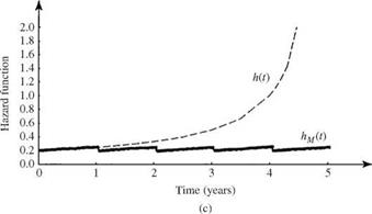
Referring to Fig. 5.6, the hazard function for the system associated with a uniform failure density function is increasing with time. This example shows that the MTTFm is larger than the MTTF, indicating that the scheduled maintenance is beneficial to the system under consideration. Furthermore, plots of the reliability, failure density, and hazard function for this example are shown in Fig. 5.14.

In the context of scheduled maintenance, the number of maintenance ap­plications KM before system failure occurs is a random variable of significant

Preventive maintenance

Preventive maintenance

Preventive maintenance

Figure 5.14 Reliability function (a) with [ps, M(t)] and without [ps(t)] pre­ventive maintenance, failure density function (b) with [ f m(t)] and without [ft(t)] preventive maintenance, and hazard function (c) with [Hm(t)] and without [H(t)] preventive maintenance for Example 5.8.

importance. The probability that the system will undergo exactly k preventive maintenance applications before failure is the probability that system failure occurs before (k + 1)tM, which can be expressed as

qk = [ Ps(tM )]k [1 – Ps(tM)] for k = 0,1,2,… (5.34)

Подпись: ps(tM ) 1 - ps(tM) Подпись: (5.35)

Подпись: TO ps(tM)]J3 k X [ps(tM)]k k = 1
Подпись: E ( KM ) = Y, k x qk = [1 k=0

which has the form of a geometric distribution. From Eq. (5.34), the expected number of scheduled maintenance applications before the occurrence of system failure is

Подпись: Var(KM) = ]Tk2 x qk - E2(KM) k=0 Подпись: [1 - ps(tM)]£k2[ps(tM)]k k = 1 Подпись: ps(tM) 2 1 - ps(tM)_

and the variance of KM is

Подпись: ps(tM) 2 1 - ps(tM)_ Подпись:ps(tM )[1 + ps(tM )]
[1 – ps(tM)]2

ps(tM )

[1 – ps(tM)]2

Preventive maintenance Подпись: x (1 - x)2 Подпись: i2xi i=1 Подпись: x(1 + x) (1 - x)3 Подпись: (5.37)

The algebraic manipulations used in Eqs. (5.35) and (5.36) employ the following relationships under the condition 0 < x < 1:

Example 5.9 Referring to Example 5.7, having an exponential failure density func­tion, derive the expressions for the expected value and variance of the number of scheduled maintenance applications before the system fails.

Подпись: E ( KM ) Подпись: ps (tM ) 1 - ps(tM) Подпись: e-ltM 1 1 1 — £~^м Q^M — 1 Q^M/MTTF 1

Solution According to Eq. (5.35), the expected number of scheduled maintenance ap­plications before failure can be derived as

Подпись: Var( KM ) Подпись: ps (tM ) [1 - ps(tM)]2 Подпись: g—XtM (1 - e-XtM )2 Подпись: QMM (ektM - 1)2 Подпись: etM/MTTF (etM/MTTF - 1)2

The variance of the number of scheduled maintenance applications before failure can be derived, according to Eq. (5.36), as

Time variations of the expected value and standard deviation of the number of sched­uled maintenance applications before failure for a system with an exponential failure density function are shown in Fig. 5.15. It is observed clearly that, as expected, when the time interval for scheduled maintenance tM becomes longer relative to the MTTF,

Подпись: Figure 5.15 Time variations of the expected value and standard deviation of the number of scheduled maintenance applications before failure for a system with an exponential failure density function, as in Example 5.9.

the expected number of scheduled maintenance applications E(Km) and its associ­ated standard deviation a ( Km ) decrease. However, the coefficient of variation Q ( Km ) increases. Interestingly, when tM/MTTF = 1, E(Km) = 1/(e — 1) = 0.58, indicat­ing that failure could occur before maintenance if the scheduled maintenance time interval is set to be MTTF under the exponential failure density function.

Example 5.10 Referring to Example 5.8, with a uniform failure density function, compute the expected value and standard deviation of the number of scheduled main­tenance applications before the system fails.

Подпись: E( KM ) Подпись: Ps (tM ) 1 — Ps(tM) Подпись: 4/5 4/5 1 - (4/5) = 1/5

Solution According to Eq. (5.32), the expected number of scheduled maintenance ap­plications before failure can be derived as

Подпись: Var( KM )Подпись: 20

Preventive maintenance

The variance of the number of scheduled maintenance applications before failure can be derived, according to Eq. (5.33), as

The standard deviation of the number of scheduled maintenance applications before failure for the system is V20 = 4.47 scheduled maintenance applications.

Imperfect maintenance. Owing to faulty maintenance as a result of human error, the system under repair could fail soon after the preventive maintenance application. If the probability of performing an imperfect maintenance is q, the reliability of the system is to be multiplied by (1 – q) each time maintenance is performed, that is,

Ps, m (t | q) = [(1 – q) ps(tM)]kPs (t – ktM) for ktM < t < (k + 1) M k = 0, 1,2,…

(5.38)

Подпись: Ps,M(ktM | q) Ps(ktM ) Preventive maintenance Подпись: for k = 0, 1, 2, ... Подпись: (5.39)

An imperfect maintenance is justifiable only when, at t = ktM,

Example 5.11 Refer to Example 5.7, with an exponential failure density function. Show that implementing an imperfect maintenance is in fact damaging.

Solution By Eq. (5.39), the ratio of reliability functions with and without imperfect maintenance for a system with an exponential failure density is

Подпись: (1 - q)k < 1 for k > 1Ps, m(ktM | q) _ (1 k (e Шм

Ps(ktM) =( q) в-шм

This indicates that performing an imperfect maintenance for a system with an expo­nential failure density function could reduce reliability.

5.3.5 Supportability

For a repairable component, supportability is an issue concerning the ability of the components, when they fail, to receive the required resources for car­rying out the specified maintenance task. It is generally represented by the time to suPPort (TTS), which may include administrative time, logistic time, and mobilization time. Similar to the TTF and TTR, TTS, in reality, also is randomly associated with a probability density function. The cumulative dis­tribution function of the random TTS is called the suPPortability function, rep­resenting the probability that the resources will be available for conducting a repair task at a specified time. Also, other measures of supportability include the mean time to suPPort (MTTS), TTSP, and suPPort success, similar to those defined for maintainability, with the repair density function replaced by the density function of the TTS.

Repair rate and its relationship with repair density and repair probability

The repair rate r (t), similar to the failure rate, is the conditional probability that the system is repaired per unit time given that the system failed at time zero and is still not repaired at time t. The quantity r (t) dt is the probability that the system is repaired during the time interval (t, t + dt] given that the system fails at time t. Similar to Eq. (5.3), the relationship among repair density function, repair rate, and repair probability is

r (t 1=t—GW,5-22’

Given a repair rate r (t), the repair density function and the maintainability can be determined, respectively, as

г c t -|

Подпись: I r(T) dr 0 Подпись:

Repair rate and its relationship with repair density and repair probability Подпись: (5.24)

gt(t) = r (t) X exp

5.1.2 Mean time to repair, mean time between failures, and mean time between repairs

The mean time to repair (MTTR) is the expected value of time to repair of a failed system, which can be calculated by

n TO n TO

MTTR = rgt (r) dr = [1 — Gt (r)] d r (5.25)

00

The MTTR measures the elapsed time required to perform the maintenance op­eration and is used to estimate the downtime of a system. The MTTR values for some components in a water distribution system are listed in the last columns of Tables 5.2 and 5.3. It is also a commonly used measure for the maintainability of a system.

The MTTF is a proper measure of the mean life span of a nonrepairable system. However, for a repairable system, the MTTF is no longer appropriate for representing the mean life span of the system. A more representative indicator for the fail-repair cycle is the mean time between failures (MTBF), which is the sum of MTTF and MTTR, that is,

MTBF = MTTF + MTTR (5.26)

The mean time between repairs (MTBR) is the expected value of the time be­tween two consecutive repairs, and it is equal to MTBF. The MTBF for some typ­ical components in a water distribution system are listed in Tables 5.2 and 5.3.

Example 5.6 Consider a pump having a failure density function of ft(t) = 0.0008exp(-0.0008t) fort > 0

and a repair density function of

gt(t) = 0.02 exp(-0.02t) for t > 0

in which t is in hours. Determine the MTBF for the pump.

Solution To compute the MTBF, the MTTF and MTTR of the pump should be calcu­lated separately. Since the time to failure and time to repair are exponential random variables, the MTTF and MTTR, respectively, are

MTTF = 1/0.0008 = 1250 hours

MTTR = 1/0.02 = 50 hours

Therefore, MTBF = MTTF + MTTR = 1250 + 50 = 1300 hours.

Repair density and repair probability

Like the time to failure, the random time to repair (TTR) has the repair density function gt (t) describing the random characteristics of the time required to re­pair a failed system when the failure occurs at time zero. The repair probability Gt(t) is the probability that the failed system can be restored within a given time period (0, t]:

Gt(t) = P(TTR < t) = f gt(t) dr (5.19)

90

The repair probability Gt (t) is also called the maintainability function (Knezevic, 1993), which is one of the measures for maintainability (Kapur, 1988b). Main­tainability is a design characteristic to achieve fast, easy maintenance at the lowest life-cycle cost. In addition to the maintainability function, other types of maintainability measures are derivable from the repair density function (Kraus, 1988; Knezevic, 1993), and they are the mean time to repair (described in Sec. 5.3.3), TTRp, and the restoration success.

TABLE 5.3 Reliability and Maintainability of Water Distribution Subsystems by Size

Subsystem

MTBF*(x106 hours)

MTTR* (hours)

Pumps (in gpm)

1-10,000

0.039600

6.786

10,001-20,000

0.031100

7.800

20,001-100,000

0.081635

26.722

Over 100,000

0.008366

9.368

Power transmission (in horsepower)

0-1

0.025370

1.815

2-5

0.011010

2.116

6-25

1.376400

25.000

26-100

0.058620

5.000

101-500

0.078380

2.600

Over 500

0.206450

32.000

Motors (in horsepower)

0-1

0.206450

2.600

2-5

0.214700

6-25

0.565600

7.857

26-100

0.062100

4.967

101-500

0.046000

12.685

Over 500

0.064630

7.658

Valves (in inches)

6-12

0.054590

13-24

0.010810

1.000

25-48

0.019070

42.000

Over 48

0.007500

2.667

Controls (in horsepower)

0-1

2.009200

2.050

2-5

0.509500

6-25

4.684900

26-100

0.026109

2.377

101-500

0.099340

5.450

Over 500

0.037700

3.125

*MTBF = mean time between failure; MTTR = mean time to repair; MTBF = MTTF + MTTR.

SOURCE : From Schultz and Parr (1981).

The TTRp is the maintenance time by which 100p percent of the repair work is completed. The value of the TTRp can be determined by solving

r TTRp

P (TTR < TTRp) = gt(t) dT = Gt(TTRp) = p (5.20)

J0

In other words, the TTRp is the pth order quantile of the repair density function. In general, p = 0.90 is used commonly.

Note that the repair probability or maintainability function Gt(t) represents the probability that the restoration can be completed before or at time t. Some­times one may be interested in the probability that the system can be restored by time t2, given that it has not been repaired at an earlier time t1. This type of conditional repair probability, similar to the conditional reliability of Eq. (5.12),

G (t ) _ G (t )

RS (ti, t2) = P [TTR < t2 | TTR > ti] = , (5.21)

1 — G(ti)

Kraus (1988) pointed out the difference in maintainability and maintenance; namely, maintainability is design-related, whereas maintenance is operation – related. Since the MTTF is a measure of maintainability, it includes those time elements that can be controlled by design. Elements involved in the evaluation of the time to repair are fault isolation, repair or replacement of a failed com­ponent, and verification time. Administrative times, such as mobilization time and time to reach and return from the maintenance site, are not included in the evaluation of the time to repair. The administrative times are considered under the context of supportability (see Sec. 5.3.4), which measures the ability of a system to be supported by the required resources for execution of the specified maintenance task (Knezevic, 1993).

Repairable Systems

For repairable hydrosystems, such as pipe networks, pump stations, and storm runoff drainage structures, failed components within the system can be re­paired or replaced so that the system can be put back into service. The time required to have the failed system repaired is uncertain, and consequently, the total time required to restore the system from its failure state to an operational state is a random variable.

Repairable Systems

Repairable Systems

20


20


15


Repairable Systems

TABLE 5.2 Reliability and Maintainability of Water Distribution Subsystems by Generic Group

Subsystem

MTBF* (x 106 hours)

MTTR* (hours)

Pumps

Centrifugal, open impeller

0.021660

7.825

Axial flow, propeller

0.074191

16.780

Power transmission

Concentric reducer

0.122640

2.000

Parallel shaft

0.710910

32.000

Right angle shaft

0.019480

1.400

Vertical shaft

0.031470

2.023

Variable speed, hydraulic

0.349500

Variable speed, other

0.014200

2.500

Gear box

0.045780

3.530

Chain drive

0.017850

8.000

Belt drive

0.091210

1.800

Motors

Multiphase

0.068000

6.853

Variable speed, ac

0.114820

8.000

Gas engine

0.023800

24.000

Valves

Gate

0.008930

3.636

Ball

0.011460

Butterfly

0.032590

1.000

Plug

0.028520

Controls

Electrical

0.100640

2.893

Mechanical

0.031230

8.000

Pressure (fluid)

0.035780

8.236

Pressure (air)

0.018690

3.556

*MTBF = mean time between failure; MTTR = mean time to repair; MTBF = MTTF + MTTR.

SOURCE : From Schultz and Parr (1981).

Effect of age on reliability

In general, the reliability of a system or a component is strongly dependent on its age. In other words, the probability that a system can be operational to perform its intended function satisfactorily is conditioned by its age. This conditional reliability can be expressed mathematically as

Подпись: Ps(M 11)

P(TTF > t, TTF > t + M)
P(TTF > t)

P(TTF > t + M) Ps(t + M) P (TTF > t) = ps(t)

in which t is the age of the system up to the point that the system has not failed, and ps(M 11) is the reliability over a new mission period M, having successfully operated over a period of (0, t ]. In terms of failure rate, ps(M 11) can be written as

t-t+M

I h(r) dr


Ps(M | t) = exp


(5.13)


Effect of age on reliability

Figure 5.10 Curves for reliability [ps(t)], failure density [ (t)], and fail­ure rate [h(t)] for the 5-mile sandspun cast iron pipe water main in Example 5.3.


t-t+f

I h(t) dr


f (fit) =-d [ vff1)]

d f


Effect of age on reliability

Ps(f i t)h(t + f)

(5.14)


Effect of age on reliability

For a process or component following the bathtub failure rate shown in Fig. 5.8 during the useful-life period, the failure rate is a constant, and the failure density function is an exponential distribution. Thus the failure rate h(t) = X. The conditional reliability, according to Eq. (5.13), is

Подпись: (5.15)Ps(f i t) = e lt

which shows that the conditional reliability depends only on the new mission period f regardless of the length of the previous operational period. Hence the time to failure of a system having an exponential failure density function is memoryless.

Подпись: Ps(f i t) Effect of age on reliability Effect of age on reliability Подпись: a Подпись: (5.16)

However, for nonconstant failure rates during the early-life and wear-out periods, the memoryless characteristics of the exponential failure density func­tion no longer hold. Consider the Weibull failure density with a = 1. Referring to Fig. 5.3, the condition a = 1 precludes having a constant failure rate. According to Table 5.1, the conditional reliability for the Weibull failure density function is

As can be seen, ps(f 11) will not be independent of the previous service period t when a = 1. Consequently, to evaluate the reliability of a system for an addi­tional service period in the future during the early-life and wear-out stages, it is necessary to know the length of the previous service period.

Example 5.4 Refer to Example 5.3. Derive the expression for the conditional reli­ability and conditional failure density of the 5-mile water main with sandspun cast iron pipe.

Solution Based on the reliability function obtained in Example 5.3, the conditional reliability of the 5-mile sandspun cast iron pipe in the water distribution system can be derived, according to Eq. (5.12), as

Подпись:ps (t + f )

Ps (t)

exp[23.25(1 — e00137(t+f 1)]
exp[23.25(1 — e00137t)]

exp[23.25e00137t(1 – e0 0137f)]

ft(§ 11) = 0.3185 x e0 0137(t+^) x exp[23.25e00137t(1 – e00137^)]

Figure 5.11 shows the conditional reliability and conditional failure density of the pipe system for various service periods at different ages. Note that at age t = 0, the curve simply corresponds to the reliability function.

5.2.5 Mean time to failure

Подпись: MTTF = E (TTF) Подпись: T ft(T) dr Подпись: (5.17)

A commonly used reliability measure of system performance is the mean time to failure (MTTF), which is the expected TTF. The MTTF can be defined math­ematically as

Подпись: MTTF Подпись: Ps(t) dt Подпись: (5.18)

Referring to Eq. (2.30), the MTTF alternatively can be expressed in terms of reliability as

0

By Eq. (5.18), the MTTF geometrically is the area underneath the reliability function. The MTTF for some failure density functions are listed in the last col­umn of Table 5.1. For illustration purposes, the MTTFs for some of the compo­nents in water distribution systems can be determined from mean time between failures (MTBF) and mean time to repair (MTTR) data listed in Tables 5.2 and 5.3.

Example 5.5 Refer to Example 5.3. Determine the expected elapsed time that a pipe break would occur in the 5-mile sandspun cast iron pipe water main.

Solution The expected elapsed time over which a pipe break would occur can be com­puted, according to Eq. (5.17), as

f TO f TO

MTTF = ps(t)dt = exp[23.25(1 – e00137t)] dt = 3.015years

00

The main reason for using Eq. (5.18) is purely for computational considerations because the expression for ps(t) is much simpler than ft(t).