Category HIGHWAY ENGINEERING HANDBOOK

Critical Depth Determination

Подпись: IOO Подпись: 150 Critical Depth Determination Подпись: 350

The critical depth for various culvert cross-sections may be found from charts in HEC 5. An example is given in Fig. 5.16 for a rectangular section. In this case, the ratio of the flow Q (ft3/s) to the width B (ft) is used to find the critical depth dc (ft). Of course, dc cannot exceed the depth of the box section.

Подпись: MOTEac CANNOT EXCEED D

Size Determination for Culverts with Outlet Control

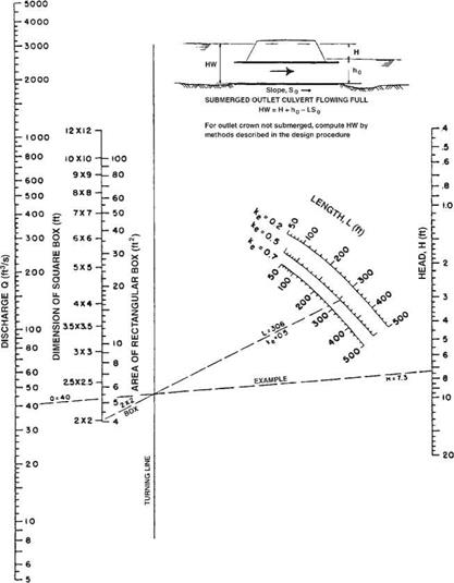
The headwater depth for a culvert operating under outlet control may be determined with the aid of the outlet control nomographs in HDS 5. An example of these nomo­graphs for box culverts is shown in Fig. 5.15. The following procedure may be used to determine the head H from the nomographs. The length L (ft), entrance coefficient ke, and design discharge must be known. Locate L on the appropriate ke curve, and connect this point with the proposed culvert size. Locate the design discharge and extend a line from that point through the turning point intersection of the previous line to read the

Size Determination for Culverts with Outlet Control

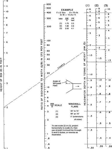
FIGURE 5.14 Flow nomograph for box culvert under inlet control. (From “Hydraulic Design of Highway Culverts," HDS 5, FHWA, with permission)

value of the head H (ft) on the right. For example, assume L = 306 ft, ke = 0.5, a 2-ft X 2-ft box, and Q = 40 ft3/s. The nomograph shows that H = 7.3 ft. The headwater depth, HW, may then be determined by geometry from the equation

Size Determination for Culverts with Outlet Control

FIGURE 5.15 Flow nomograph for box culvert under outlet control with n = 0.012. (From "Hydraulic Design of Highway Culverts," HDS 5, FHWA, with permission)

where the terms are defined by the inset figure in the nomograph. (Note: To use the chart with SI units, first convert from SI units to U. S. Customary units—1 ft = 0.305 m, 1 ft2 = 0.0929 m2, 1ft3/s = 0.0283 m3/s). Where the outlet is submerged, ho is equal to the tail – water depth just downstream of the outlet and may be calculated from Manning’s equa­tion as applied to the channel. Where the outlet is not submerged, ho is equal to the greater of the tailwater depth or one-half of the sum of the culvert height plus the critical depth, (dc + D)/2. By examining different alternatives, a culvert can be selected that pro­vides the required flow within the allowable headwater depth.

Size Determination for Culverts with Inlet Control

Once the design discharge and allowable headwater are determined and the culvert alignment and slope decided upon, an efficient culvert size may be found through the use of nomographs as shown in “Hydraulic Design of Highway Culverts,” Hydraulic Design Series 5, FHWA.

An example of an inlet control nomograph is shown in Fig. 5.14. Since the structure size is not known, the design is an iterative process. To use the chart, the trial culvert size and inlet configuration, design discharge, allowable headwater depth, culvert length, and culvert slope must be known. The relationship of the inlet control headwater to the diameter or height of the culvert (HW/D) is read directly from the inlet control nomograph by extending a line from the culvert size scale (left scale) through the discharge/bottom width ratio scale (center scale) to the scale of the headwater depth in terms of height (right scale). The inlet control headwater equals this value multiplied by D. For example, assume a 5-ft X 2-ft box culvert with the design storm, Q, equal to 75 ft3/s. The nomograph shows that HW/D = 1.75, 1.90, or 2.05, depending upon the inlet configuration. By multiplying these values by the box rise of 2 ft, the correspond­ing headwater depths are found to be 3.5 ft, 3.8 ft, and 4.1 ft, respectively. (Note: To use the chart with SI units, first convert from SI units to U. S. Customary units—1 ft = 0.305 m, 1ft3/s = 0.0283 m3/s).

Allowable Headwater Depth

The allowable headwater depth is the depth of ponded water permitted at the entrance to a culvert. Allowable headwater depths are generally classified as either physical controls or arbitrary controls.

Physical headwater controls are topographic features that should be protected against periodic inundation. They include the roadway pavement and upstream pro­ductive property or structures. Additionally, high points between adjacent watersheds should typically be used as physical headwater controls. The use of a watershed break elevation as a headwater control will protect against the unnecessary diversion of runoff from a watershed to an adjacent watershed.

Arbitrary headwater controls are typically used to ensure the efficient operation of the culvert while protecting the roadway embankment from erosion and subsequent washout. The control may be a function of either the design flood or the base flood. Typical limits include a percentage of the barrel diameter or rise such as 1.2D or 120 percent of the barrel diameter or rise, or a permitted depth of ponding above the barrel such as D + 2 ft. Greater depths of ponding for the base flood are typically per­mitted. Large-span structures usually have more restrictive limitations.

Inlet and Outlet Control

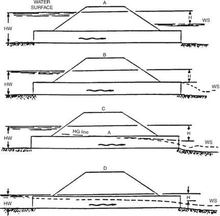
There are two types of flow in culverts: inlet control and outlet control. Accurate pre­diction of the condition of flow is difficult, and an assumption of the most conservative control may at times be warranted. Figures 5.12 and 5.13 depict several conditions of inlet and outlet control.

For inlet control, the discharge capacity is controlled at the upstream or inlet end. Factors that have an effect on the culvert performance under this condition are the headwater elevation, the inlet area of the barrel, and the inlet configuration. For outlet control, the discharge is controlled at the downstream end. Additional factors affecting performance under this condition include the tailwater elevation, characteristics of the culvert barrel (slope, length, roughness, shape, and cross-sectional area), and the outlet configuration.

With inlet control, the culvert usually flows only partially full; the roughness, slope, length, and outlet condition of the culvert do not affect the discharge capacity. The headwater depth is measured from the invert. The inlet area is generally the same as the cross-sectional area of the barrel. However, when tapered or beveled inlets are utilized, the face area is enlarged and the control area is at the throat. The efficiency of a culvert is greatly affected by the inlet configuration and may be heightened by the use of beveled edges and tapered inlets, which reduce the contraction of the flow, thereby effectively enlarging the face area. Bevels are large chamfers or rounded corners at the inlet. Tapered inlets may be tapered either at the sides or at the bottom (slope tapers). Either type will increase the flow capacity or, conversely, decrease the head­water elevation for a given capacity. Prior to their use, the cost of the improved inlet should be compared with the savings from the use of a smaller barrel.
Inlet and Outlet ControlINLET SUBMERGED

MEDIAN

DRAIN

HW fv——————————————–

Подпись: WATER SURFACE
Inlet and Outlet Control
Подпись: INLET UNSUBMERGED
Подпись: MW
Подпись: WS

INLET SUBMERGED

FIGURE 5.12 Illustration of culvert under inlet flow control. (From Highway Drainage Guidelines,

Vol. IV, American Association of State Highway and Transportation Officials, Washington, D. C., 1999, with permission)

Inlet and Outlet Control Inlet and Outlet Control Подпись: Ц2 2g Подпись: (5.21)

The coefficient ke, which represents the efficiency of the culvert inlet, is listed in Table 5.9 for many different designs. It may be used to calculate the head loss at the entrance from the equation

where He = entrance head loss, ft (m) ke = energy coefficient V = velocity, ft/s (m/s)

g = acceleration of gravity, 32.2 ft/s2 (9.8 m/s2)

Extensive research by the Bureau of Public Roads and later work by the Federal Highway Administration established a series of equations for determining the headwater at a culvert entrance. In addition, a series of nomographs for the solution of the equa­tions for the various culvert materials were prepared. This information is available in the FHWA publication HDS 5, “Hydraulic Design of Highway Culverts.” The charts in HDS 5 are arranged in groups according to shapes and materials. The charts include the types, materials, and inlet configurations listed below:

1. Circular concrete pipe with both square-edge and groove-edge inlets

2. Circular corrugated metal pipe

Inlet and Outlet Control

FIGURE 5.13 Illustration of culvert under outlet flow control. (From Highway Drainage Guidelines,

Vol. IV, American Association of State Highway and Transportation Officials, Washington, D. C., 1999, with permission)

3. Concrete boxes with headwalls or wingwalls, with or without beveled or chamfered inlets

4. Corrugated metal box culverts with earth, concrete, or metal inverts

5. Horizontal and vertical elliptical concrete pipe with both square-edge and groove – edge inlets

6. Corrugated metal pipe-arch

7. Corrugated metal structural plate pipe-arch with 18-in (450-mm) and 30-in (750-mm) corner radii

8. Corrugated metal arch culverts with earth, concrete, or metal inverts

9. Various shapes of structural plate long-span culverts

10. Various shapes of culverts with slope-tapered and side-tapered improved inlets

TABLE 5.9 Entrance Loss Coefficients for Culverts under Outlet Control, Flowing Full or Partly Full

Type of structure and design of entrance

Coefficient k

e

Pipe, concrete

Projecting from fill, socket end (groove end)

0.2

Projecting from fill, square-cut end

0.5

Headwall or headwall and wingwalls

Socket end of pipe (groove end)

0.2

Square edge

0.5

Rounded, radius = (Yn)D

0.2

Mitered to conform to fill slope

0.7

End section conforming to fill slopes*

0.5

Beveled edges, 33.7° or 45° bevels

0.2

Side – or slope-tapered inlet

0.2

Pipe, or pipe-arch, corrugated metal

Projecting from fill (no headwall)

0.9

Headwall or headwall and wingwalls, square edge

0.5

Mitered to conform to fill slope, paved or unpaved slope

0.7

End section conforming to fill slope*

0.5

Beveled edges, 33.7° or 45° bevels

0.2

Side – or slope-tapered inlet

0.2

Box, reinforced concrete

Headwall parallel to embankment (no wingwalls)

Square-edged on 3 edges

0.5

Rounded on 3 edges to radius of >12 barrel

dimension, or beveled edges on 3 sides

0.2

Wingwalls at 30° to 15° to barrel

Square-edged at crown

0.4

Crown edge rounded to radius of >12 barrel

dimension, or beveled top edge

0.2

Wingwall at 10° to 25° to barrel

Square-edged at crown

0.5

Wingwalls parallel (extension of sides)

Square-edged at crown

0.7

Side – or slope-tapered inlet

0.2

*“End section conforming to fill slope,” made of either metal or concrete, is the section commonly available from manufacturers. From limited hydraulic tests it is equivalent in operation to a headwall in both inlet and outlet control. Some end sections, incorporating a closed taper in their design, have a superior hydraulic performance. These latter sections can be designed using the information given for the beveled inlet.

Source: From Hydraulic Design of Highway Culverts, HDS 5, FHWA, with

permission.

The charts may also be used for plastic pipes. The appropriate chart selection should be based on a comparative entrance configuration and barrel roughness.

The reader is urged to obtain a copy of this document since it is the primary method used for culvert design and the nomographs it contains are an indispensable design aid.

If a culvert operates under outlet control with a free-water surface along the entire length of the culvert, the nomographs should not be used. In lieu of the nomographs, a backwater calculation should be performed.

General Considerations

The most common materials used are concrete, steel, aluminum, and plastic. The material used may affect the hydraulic capacity of the culvert, as different materials and wall configurations have different entrance loss coefficients and coefficients of roughness. The choice of the material is often controlled by structural and durability considerations.

The inlet configuration generally has a direct effect on the hydraulic capacity of the cul­vert and the backwater upstream from the site. The natural channel approaching the culvert is usually wider than the culvert, and thus the inlet operates as a flow contraction and can be the control for determining the hydraulic capacity. In many instances, the culvert is designed to operate hydraulically with the inlet submerged. This is one advantage that cul­verts have over bridges, which are designed for freeboard between the high-water elevation and the soffit. If the inlet provides for a gradual transition from the wider natural channel to the narrower culvert barrel, energy losses can be limited. Figure 5.11 depicts some com­mon transitions used to improve culvert hydraulics. Some of the common end treatments used at inlets and outlets include projecting ends, mitered ends, flared ends, and headwalls and wingwalls.

Projecting ends exist when the barrel of the culvert extends out from the face of the embankment. This is probably the least expensive but most hydraulically inefficient of the listed end treatments. It is unsightly, is potentially hazardous to traffic, and can induce scour damage. For these reasons its use should be limited to smaller culverts.

General Considerations

Подпись: 390

(b)

FIGURE5.il (Continued)


General ConsiderationsGeneral ConsiderationsGeneral ConsiderationsGeneral Considerations

Mitered ends exist where the culvert is formed or manufactured to be in the same plane as the embankment. Mitered ends, when compared with projected ends, are more aesthetically pleasing. However, the projected end is structurally more stable and the mitered end may require the addition of a headwall to compensate for this instability. The hydraulic efficiency of both the mitered and the projected inlets is approximately the same.

Flared ends are generally precast or prefabricated for use with concrete, corrugated steel or aluminum, and plastic pipes. They are used to retain the earth embankment and provide a hydraulic efficiency comparable to that of a headwall.

Headwalls and wingwalls are usually cast-in-place structures. They are designed to retain the embankment, improve hydraulics, prevent erosion, and, in larger-diameter flexible structures, provide support at the inlet and outlet ends. Retaining the earth has an economic benefit for larger structures in that the culvert may be shortened, thereby providing cost savings. The hydraulics may be improved by skewing or warping the wingwalls to provide for a smooth transition between the wider channel and the nar­rower barrel.

The preferred location of the culvert is in the natural streambed. This alignment usually provides for efficient inlet and outlet configurations and keeps construction costs to a minimum by limiting excavation and backfill work. Aligning the culvert in this manner can result in an inordinately long structure if the natural channel is on a high skew (over 45°) with respect to the roadway. This may be avoided by realigning the channel so that the culvert is placed perpendicular to the highway, but this may lead to erosion and siltation problems. Erosion may occur where the channel is angled to provide for the perpendicular crossing. Siltation may occur as the slope is necessarily reduced because the flow travels a longer distance to traverse the roadway. If a perpen­dicular culvert crossing is determined to be appropriate, it should be aligned so that the necessary channel realignment occurs downstream of the roadway embankment.

HYDRAULIC DESIGN OF CULVERTS

Culverts convey surface flow from one side of the roadway to the other. Culvert design comprises three general considerations: culvert size, location, and shape. The size of the culvert is directly related to the results of the hydrologic investigation. The location of the culvert is derived from the site geometry and comprises the alignment, length, and

slope. The site hydraulics and available roadway fill height (height of fill from creek bed to profile grade) are the controlling criteria for determining the shape of the culvert. However, shapes, sizes, and material types used for culvert construction can be precluded from use based on manufacturing limitations. Since only the site hydrology and geomet­rics are known and all other parameters are variable, a trial and selection process must be used to determine the appropriate culvert size and type.

Subgrade Drainage

As indicated previously, subgrade drainage is designed to handle surface water inflow, whereas subdrains are designed to accommodate encroaching groundwater. Surface water can enter the pavement subsection through joints, cracks, and infiltration of the pavement. Rapid drainage of the pavement structural section is necessary to minimize piping and swelling of the subgrade material, and the subsequent increased deflections and cracking of the pavement surface. This rapid drainage can best be achieved by placing a highly permeable drainage layer under the full width of the pavement and allowing it to drain the infiltration to an edge drain. Figure 5.10 illustrates edge drain designs using either a pipe (perforated or slotted) in a trench filled with a permeable material, or a geocomposite panel drain.

Subgrade Drainage

(a)

Subgrade Drainage

(b)

FIGURE 5.10 Typical pavement edge drains. (a) Pipe edge drain; (b) geocomposite panel drain.

Subsurface Drainage

Saturation of the structural section under the roadway (subgrade and base course) and the foundation materials is a primary cause of early roadbed failure because of decreased ability to support heavy truck loads. Saturated conditions can lead to piping of fines and frost damage or icing of the roadway surface. Designs to prevent water from infiltrating beneath the pavement will lead to longer-lasting and more economical roadbed sections. Designs typically include subsurface drainage (subdrains) to intercept and reroute encroaching groundwater and subgrade drainage to handle surface water inflow.

The design of subsurface drainage begins with flow determination. Although this may be determined by analytical methods, it is usually cumbersome and unsatisfactory to do so. Field explorations will generally yield better results. These investigations should include soil and geological studies, borings to find the elevation and extent of the aquifer, and measurements of the groundwater discharge. The investigation should be thorough and should be conducted during the rainy season or during snow melt if the region has snow cover. It may involve digging a trench or pit to aid in estimating flow. After the design flow is established, the pipe may be sized using Manning’s equation, Eq. (5.11).

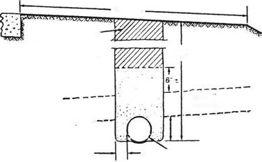
The standard underdrain consists of a perforated pipe near the bottom of a narrow trench. The trench is filled with a permeable material and may be lined with filter fabric if the trench is excavated in erodable soils. Figure 5.9 illustrates an underdrain used to intercept sidehill seepage.

The following considerations apply to the design of subsurface drainage:

1. Surface drainage should not be allowed to discharge into the subsurface drainage system.

2. Outlets for the underdrain system should be provided for at intervals not exceeding 500 ft (150 m) to 1000 ft (300 m), depending upon the porosity of the base course.

Подпись: Wf •їТї/ГГіЛ*

Подпись: Surface Water Subsurface Drainage Subsurface Drainage Подпись: Shoulder
Подпись: Tamped Earth Such as to Eliminate
Subsurface Drainage
Подпись: Tamped
Подпись: Zone

Subsurface DrainageImpervious Zone

3"min. ^6" Min. Diameter Pipe

FIGURE 5.9 Intercepting drain in impervious zone for keeping free water out of road­way and subgrade. Conversion: 1 in = 25.4 mm. (From Handbook of Steel Drainage and Highway Construction Products, American Iron and Steel Institute, 1994, with permission)

Outlet may run into the storm drain system as long as there is no possibility of back­flow due to a buildup of hydrostatic pressure.

3. Pipe underdrains should be placed on grades steeper than 0.5 percent if possible. Minimum grades of 0.2 percent are acceptable.

4. The depth of the underdrain will depend upon the permeability of the soil, the ele­vation of the aquifer, and the amount of necessary drawdown to achieve stability.

5. Pipes for underdrains may be made of metal, plastic, concrete, clay, asbestos cement, or bituminous fiber. Two types of openings are used to allow the ground­water into the pipe: perforated and open-jointed. Open-jointed pipes such as clay and concrete drain tiles are limited to areas where the admission of excessive solids through the joints may be avoided.

(See “Pavement Subsurface Drainage Design,” FHWA-NHI-99-028, and “Pavement

Subsurface Drainage Systems,” NCHRP Synthesis 239, TRB, 1997.)

Culverts and Storm Drains

The open-end conduits used to convey water from one side of the roadway through the embankment to the other side are typically referred to as culverts. A network or system of conduits to carry storm water intercepted by inlets is referred to as a storm drain system. Conduits for culverts and storm drains are available in many different shapes, sizes, and materials, as discussed subsequently. Available shapes include circular, elliptical (horizontal or vertical), pipe-arch, arch, and box shapes. Factors that affect the shape at a particular site include the fill height, construction costs, and potential for clogging by debris. Where the cover over the conduit is limited, pipe-arch, arch, elliptical (horizontal), or box shapes may be more applicable. Where the fill height is great, circular shapes tend to be structurally and economically more favorable. Factors involved in the selection process include hydraulic, structural, construction, mainte­nance, and durability requirements. (See Art. 5.5 for hydraulic design of culverts.)

A system of closed conduits (storm drains and culverts) to convey the runoff from the inlets to the outfall must be designed starting at the upstream end and proceeding downstream. Each section of pipe that extends from inlet to inlet, or from an inlet to the final outfall, is called a run. Each run requires a separate analysis because of the change in flow at each, and possible changes in slope, pipe size, and type. After all runs are initially sized, the hydraulic grade line is developed (Art. 5.3.4). Unlike the sizing of the conduits, the calculations for this proceed in an upstream direction. In addition to head loss from friction along the length of the culvert, the hydraulic grade line must account for the effects of losses caused by turbulence at junctions and bends. Once the hydraulic grade line is established, it may be compared with the grade line of the system to ensure that it does not exceed an allowable high-water elevation. If it should extend above these allowable elevations, then the initial design must be adjusted.

In addition to system sizing based on hydraulic requirements, conduits should generally not be smaller than 12 to 18 in (300 to 450 mm) in diameter, and should have a minimum velocity of not less than 2.5 ft/s, to reduce the potential for debris clogging. Greater minimum diameters may be appropriate in some cases, particularly under high fills.

Flow in storm drains is assumed to be steady uniform flow. With this assumption, one of two hydraulic design approaches for sizing the run may be used, either open – channel flow or pressure flow. Open-channel flow assumes the flow in the conduit is open to atmospheric pressure; that is, the depth of the flow must be less than the height of the conduit. Pressure flow assumes the conduit is full with the wetted perimeter equal to the complete perimeter of the conduit. In this case, unlike open – channel flow, a pressure head will be above the conduit.

The maximum possible flow in a circular conduit under open-channel flow occurs when the barrel is approximately 95 percent flowing full. This is referred to as just – full capacity or just-full discharge.

Storm drain systems based on open-channel flow will have larger conduits than those based on pressure flow. This allows for a slight factor of safety when there is an unanticipated increase in runoff, which is desirable because the determination of the flow entering the system is not an exact science. However, initial construction costs will be somewhat higher.

If the design is based on pressure flow, the inlet and access hole elevations will be the allowable high-water elevations and should not be exceeded. Additionally, existing systems may need to be analyzed assuming pressure flow in order to accommodate new design flows.

It is common among state departments of transportation to design storm drain sys­tems using both open-channel flow and pressure flow. The system is initially designed for the just-full capacity using a lesser design frequency, say a 5-year or 10-year design frequency. After this initial sizing, the elevation of the hydraulic grade line is checked using the same or greater design frequency. The hydraulic grade line is then compared to critical high-water elevations, which should not be exceeded.

The storm drain system can outfall into a body of water, a stream or river, an existing storm drain system, or a channel. Conformance to National Pollutant Discharge Elimination System (NPDES) and local water quality regulations may be necessary whenever discharging pavement runoff. (See Chap. 1.) Regardless of the type of outfall, the flow line of the outfall should be lower than the elevation of the outlet. The outlet should be positioned so that the flow of the outfall is directed downstream, thus limiting erosion. (See Highway Drainage Guidelines, Vol. IX, AASHTO, 1999; and Design and Construction of Storm and Sanitary Sewers, ASCE, 1986.)