Category HIGHWAY ENGINEERING HANDBOOK

Inlet Location and Type

One of the major objectives in the design of the roadway drainage system is to limit the encroachment of the flow to that developed in the roadway drainage guidelines. However, this spread cannot be determined until the inlet is located. After the inlet is located, the drainage area contributing to the flow into that inlet is determined. Discharge based on the rational method is then calculated, and finally the spread is deter­mined based on that discharge and the gutter characteristics. If the spread is found to be too great (leading to possible unsafe conditions) or too small (possibly indicating an inefficient design), the inlet should be relocated and the process repeated. As can be seen, this design is an iterative process. The process is also controlled by surface features that restrict possible location of inlets, such as streets, driveways, and utilities.

There are also areas where inlets are nearly always required. These include sag points, points of superelevation reversal, street intersections, and at bridges. Where an inlet is required in the vicinity of a driveway, it should always be located upstream of the driveway. If it is located downstream, the driveway may affect the flow and cause a significant portion to bypass the inlet.

Finally, the type and size of the inlet have a direct affect on location and spacing. Similarly, designing for greater spread and allowing some bypass of the upstream inlets to occur with the residual being intercepted by those farther downstream (carry­over flow) will result in fewer inlets.

The basic types of inlets are the curb-opening inlet and the grate inlet, as shown in Fig. 5.7. Two other types frequently used are the slotted drain inlet and the combina­tion inlet (grate plus curb opening) shown in Fig. 5.8.

Curb-opening inlets, which have the drainage opening in the face of the curb, are very durable and are comparatively free from blockage by debris. This type generally relies heavily on the bordering depression to be effective at intercepting the water flow and is relatively inefficient when located in an on-grade situation. It is probably the most efficient inlet type at sag points because of its tendency to remain free of clogging by debris and its large, hydraulically efficient opening. In addition, this type of inlet opening offers little interference to vehicular traffic, pedestrians, or bicyclists. For curb-opening inlets on continuous grades, a window length that permits approxi­mately 15 percent bypass is considered optimum.

The length of the opening required for total interception of the gutter flow can be determined by the following equation:

Inlet Location and Type

FIGURE 5.7 Perspective views of grate inlet and curb-opening inlet. (From Urban Drainage Design Manual, HEC 22, FHWA, with permission)

Inlet Location and Type

FIGURE 5.8 Perspective views of combination and slotted drain inlets. (From Urban Drainage Design Manual, HEC 22, FHWA, with permission)

L = KQ0A2S03(nSX)-06 (5.20)

where Lt = length of curb opening for total interception of flow, ft (m)

Q = discharge, ft3/s (m3/s)

S = longitudinal slope of gutter n = Manning’s roughness coefficient SX = transverse slope of gutter K = 0.6 for U. S. Customary units (0.817 for SI units)

Where there is a depression, the equivalent transverse slope Se must be determined and used for SX (See Urban Drainage Design Manual, HEC 22, FHWA, for a complete dis­cussion of this and flow at sag points.)

Grate inlets come in a variety of shapes and sizes and are efficient where debris is not a problem. However, most inlets are subject to varying amounts of debris, and the selection of grate inlets, especially those located at sag points, must take this possibility into account.

For greatest hydraulic efficiency, grate inlets should be oriented with grate bars parallel to the surface flow. However, grate bars oriented parallel with traffic can cause problems where bicycles are present, and specifically designed “bicycle-proof’ grates with additional transverse bars should be used. Other factors influencing the hydraulic capacity of this type of inlet include the longitudinal and cross-slope of the gutter, the width and length of the gutter, and the size and shape of the bars. The grate inlet will intercept all of the flow that passes over the top of the grate as long as the grate is long enough. In addition, a por­tion of the side flow, or the flow that is located above the grate toward the roadway center­line, will be intercepted. The amount of the intercepted side flow depends upon the velocity of the flow, the length of the inlet, and the cross-slope of the gutter.

Combination grates—generally, curb-opening and grate inlets—are desirable at sag points. The curb opening will generally keep the inlet from clogging. At grade loca­tions, however, the efficiency of the combination inlet approaches that of the grate inlet.

Slotted drains can provide continuous interception of the flow when used on grades. However, because of the possibility of clogging, they should be used only in combination with other types of inlets at sag points. Slotted drains are also useful to supplement the existing drainage system where the roadway needs to be widened.

Inlets at grade sags deserve additional deliberation, since any blockage of the inlet will typically lead to flooding. Typical design considerations are to provide additional inlets or base the design on a relatively high assumption of debris blockage.

Curbs, Gutters, and Inlets

The roadway surface water can be removed by a series of drains that carry the water into a collection and disposal system. The curb, gutter, and inlet design must keep flooding within the parameters established in roadway drainage guidelines. The hydraulic efficiency of inlets is related to the roadway grade, the cross-grade, the inlet geometry, and the design of the curb and gutters.

Curbs are divided into two classes: barrier and mountable. Barrier curbs are steep­faced and generally 6 to 8 in (150 to 200 mm) high. Mountable curbs are generally 6 in (150 mm) high or less with relatively flat sloping faces to allow vehicles to cross them when required. Neither barrier curbs nor mountable curbs should be used on high­speed roadways. (See Chap. 6, Safety Systems.)

Gutters begin at the bottom of the curb and extend toward the roadway a varying distance, usually 1 to 6 ft (300 to 1800 mm). They may or may not be constructed with the same material as the roadway.

The longitudinal grade of the gutter is controlled by the highway grade line. For drainage purposes, it is important to maintain some minimum longitudinal slope to
ensure that runoff does not accumulate in ponds. Gutter cross-slopes of 5 to 8 percent should be maintained for a distance of 2 to 3 ft (600 to 900 mm) for that portion of the gutter adjacent to the curb.

Подпись: Q Подпись: K_ n Подпись: 1.67S 0.5T 2.67 Подпись: (5.19)

The following modification of Manning’s equation may be used to determine the spread of the gutter flow as well as the maximum depth at the curb face. This applies to a section with a single cross-slope. (For additional information, nomographs, and flow solutions for gutters with composite cross-slopes, see Urban Drainage Design Manual, HEC 22, FHWA.)

where Q = rate of discharge, ft3/s

K = 0.56 for U. S. Customary units (0.376 for SI units) n = Manning’s coefficient of roughness SX = cross-slope S = longitudinal slope

T = spread or top width of flow in gutter = d/Sx, ft d = depth of flow at face of curb, ft

Example: Gutter Flow Spread and Depth. A concrete gutter for a roadway with a grade of 0.05 and a cross-slope of 0.04 must accommodate a flow of 1.4 ft3/s. Determine the spread of the flow and its depth at the curb face. Assume n = 0.15. Substitute in Eq. (5.19) and solve for the spread T as follows:

1.4 = ( KK )(0.04)1 67(0.05)05T267

T267 = 36.23

T = 3.84 ft (1.17 m)

It follows that the depth at the curb is d = TSX = 3.84 X 0.04 = 0.15 ft (46 mm).

DESIGN OF ROADWAY DRAINAGE

Roadway drainage includes the entire system from pavement drainage through storm drains. Drainage features that make up the system include curbs, gutters, drop inlets, median drains, overside drains, roadside ditches, and storm drains. The basic design procedure for roadway drainage includes hydrology, surface water removal, and dis­posal. A properly designed system must adequately accommodate the design runoff by removing it from the roadway surface and conveying it to the outfall, avoiding damage to adjacent property and roadway hazards from overflowing and ponding.

3.4.1 General Considerations

Pavement may be drained in one of two ways. The runoff may be allowed to sheet – flow across the roadway surface and into roadside ditches. This may not always be possible or cost-effective, because of right-of-way constrictions. Alternatively, a curb and gutter section is used to channel the flow.

DESIGN WATER SPREAD

Подпись: t C-J ■— h ■- ■* -_ 4

~1 LCURB and SHOULDER^ GUTTER

FIGURE 5.6 Illustration of design water spread. (From Highway Drainage Guidelines, Vol. IX, American Association of State Highway and Transportation Officials, Washington, D. C., 1999, with permission)

An appropriate design storm must be selected so that the drainage facilities may be properly designed. This design storm must relate to an acceptable level of flooding of the roadway with regard to both area and frequency. The acceptable level of flooding is termed the design water spread (Fig. 5.6) and is defined by the acceptable amount of encroachment on the roadway surface that is assumed to have a certain probability of occurrence. It may not be economically feasible to completely prevent encroach­ment on the roadway. Alternatively, it is unwise to allow spread that results in unsafe driving conditions. Greater water spread produces hydroplaning, greater splash and spray effect, and an accompanying decrease in visibility and vehicle control by the users of the facility. The amount and frequency of encroachment should vary with the type of roadway being designed, because roads with higher volumes and speeds can tolerate less loss of visibility than local and collector roads.

AASHTO has developed general guidelines on highway drainage that may be used to formulate roadway surface drainage criteria. Table 5.7 shows the suggested AASHTO procedure for relating the road classification, the frequency of the design storm, and

TABLE 5.7 Minimum Design Frequency

Design spread

Road classification

Design frequency, years

Shoulder

or

parking

Partial driving lane

(К, 12, З4)

<10

10

50

1. High-volume divided highway

a. <45 mi/h (70 km/h)

x

x

b. >45 mi/h (70 km/h)

x

x

c. Sag point

x

x

2. High-volume bidirectional

a. <45 mi/h (70 km/h)

x

x

b. >45 mi/h (70 km/h)

x

x

c. Sag point

x

x

3. Collector

a. <45 mi/h (70 km/h)

x

x

b. >45 mi/h (70 km/h)

x

x

c. Sag point

x

x

4. Local streets

a. Low ADT*

x

x

b. High ADT

x

x

c. Sag point

x

x

*Average daily traffic.

Source: From Highway Drainage Guidelines, Vol. IX, American Association of State

Highway and Transportation Officials, Washington, D. C., 1999, with permission.

Design

storm

Design water spread

Highway type/category/feature

4% 10% (25 yr) (10 yr)

or parking lane

outer

lane

Local

standard

Freeways

Through traffic lanes, branch connections, and other major ramp connections

x —

x

Minor ramps

— x

x

Frontage roads Conventional highways

—x

x

High-volume, multilane, speeds over 45 mi/h (70 km/h)

x—

x

High-volume, multilane, speeds 45 mi/h (70 km/h) and under

—x

x

Low-volume, rural, speeds over 45 mi/h (70 km/h)

x—

x

Urban, speeds 45 mi/h (70 km/h) and under All state highways

—x

x

Depressed sections that require pumping: Use a 2% (50-year) design storm for freeways and conventional state highways. Design water spread at depressed sections should not exceed that of adjacent roadway sections. A 4% (25-year) design storm may be used on local streets or road undercrossings that require pumping.

Source: From Highway Design Manual, California Department of Transportation, with permission.

the design spread. However, more specific local or regional guidelines are usually developed and should be referenced for highway drainage design. An example of a regional guideline developed by the California Department of Transportation (Caltrans) is shown in Table 5.8. It is apparent that a more severe storm (25-year versus 10-year mean recurrence interval) is used for roadways with higher volumes and speeds, as well as a more limited design water spread.

Critical Flow Depth

When the depth of flow is plotted against the specific energy, the specific energy diagram may be obtained and the critical depth found as illustrated in Fig. 5.5. The critical depth is defined as that depth where the specific energy is minimum. The flow velocity at the

Critical Flow DepthCritical Flow DepthШШїші

HTDKAUlic graoe LINE

channel bottom

DATUM LINE

FIGURE 5.4 Flow characteristics for uniform open-channel flow. (From F. S. Merritt, ed., Standard Handbook for Civil Engineers, McGraw-Hill, 2004, with permission)

Supercritical

range

(critical

depth)

Подпись:(Specific energy)

FIGURE 5.5 Specific energy diagram. (From Highway Design Manual, California Department of Transportation, with permission)

critical depth is called the critical velocity. The channel slope that causes the critical depth and critical velocity is termed the critical slope. If the depth is greater than the critical depth, the flow is said to be subcritical and the velocity head reduces. Where the depth is less than the critical depth, the flow is said to be supercritical and the velocity head increases. For any particular energy level, except where the depth is critical, there are two corresponding depths that may occur. However, the depth may not alternate between these two values without a change in the channel configuration or slope.

Although the critical depth gives the greatest discharge, flow that causes the depth to be close to critical should be avoided, and thus the critical slope should be avoided. Flows near the critical depth may be turbulent. Inspection of the specific energy diagram reveals that where the depth is close to the critical depth, it takes little energy to change the flow from subcritical to supercritical or the reverse. If the flow does change from subcritical to supercritical, a hydraulic jump will occur. If placing the depth of flow near critical is unavoidable, it is advisable to assume the least favorable type of flow for design purposes. The critical depth may be determined from the following relationship:

Подпись: (5.14)TT = 62 T g

where A = cross-sectional flow area, ft2 (m2)

T = top width of channel flow, ft (m)

Q = discharge, ft3/s (m3/s) g = acceleration of gravity, 32.2 ft/s2 (9.8 m/s2)

Подпись: V c Подпись: (5.15)
Critical Flow Depth

For a channel with vertical walls, the velocity corresponding to the critical depth is given by

where Vc = critical velocity, ft/s (m/s). Also, for a channel with vertical walls, the flow area at a point of critical depth dc is

Подпись: (5.16)A = T(dc)

Critical Flow Depth Подпись: TTY/3 gT2 ) Подпись: (5.17)

Substitution in Eq. (5.14) leads to

It can be seen from this relationship that for a given flow, as the width of the channel changes the critical depth also changes. Such locations should be investigated for a hydraulic jump.

Points of control are locations where the depth of flow may be easily determined. The critical depth is one point of control and may be found in several typical loca­tions. As discussed above, one of these locations may be where there is a change in the channel section. Other typical locations are where the slope changes abruptly from flat (subcritical) to steep (supercritical), at the crest of an overflow dam or weir, and at the outlet of a culvert on a subcritical slope discharging into a basin or wide channel.

The Froude number (Fr) may also be used in determining whether the channel is under supercritical, critical, or subcritical flow:

Подпись: (5.18)V

(gdh)1/2

where d. = A/T. If Fr < 1.0, the channel flow is subcritical; if Fr = 1.0, the channel flow is critical; and if Fr > 1.0, the channel flow is supercritical.

Water surface profiles for the gradually varying flow condition may be determined by either the direct step method or the standard step method. The former method is applicable only to straight prismatic channel sections with gradually varying areas of flow. The standard step method may be used in nonprismatic channel sections and channel alignments that are not straight. Where the flow is subcritical, the analysis for determination of the water profile begins at the control point and proceeds upstream. Where the flow is supercritical, the opposite is true. (See V. T. Chow, Open-Channel Hydraulics, McGraw-Hill, 1959; and F. S. Merritt, ed., Standard Handbook for Civil Engineers, McGraw-Hill, 1996.)

Example: Critical Depth and Critical Velocity. A channel has a width of 10 ft (3 m)

and vertical sides. Determine the critical flow depth and critical velocity for a flow of 1000 ft3/s (28 m3/s).

U. S. Customary units:

From Eq. (5.17), dc = (Q2/gT 2)1/3 = [(1000)2/32.2(10)2]1/3 = 6.77 ft.

From Eq. (5.16), A = T(dc) = 10(6.77) = 67.7 ft2.

From Eq. (5.15), the critical velocity is Vc = (gA/T )1/2 = (32.2 X 67.7/10)1/2 = 14.8 ft/s. SI units:

From Eq. (5.17), dc = [(28)2/9.8(3)2]1/3 = 2.07 m.

From Eq. (5.16), A° = 3(2.07) = 6.21 m2.

From Eq. (5.15), Vc = (9.8 X 6.21/3)1/2 = 4.5 m/s.

Energy Equation

The energy equation is based on the principle that energy must be conserved; that is, the energy at any one cross-section on a stream is equivalent to the energy at any other section plus any intervening energy losses. This relationship, a form of the Bernoulli equation, may be used wherever there is a change in the size, shape, or slope of the channel and is useful in determining the depth of flow.

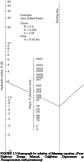
Подпись: FIGURE 5.3 Nomograph for solution of Manning equation. (From Highway Design Manual, California Department of Transportation, with permission)
Energy Equation

/ V2 І V2

z1 + d1 + у j = z2 + d2 + у ^Lg j + hL (5.13)

where zn = distance above some datum, ft (m) dn = depth of flow, ft (m)

Vn = flow velocity, ft/s (m/s) g = acceleration of gravity, 32.2 ft/s2 (9.8 m/s2) hL = head loss between the two sections, ft (m)

TABLE 5.6 Values of the Roughness Coefficient n for Use in the Manning’s Equation

Min

Avg

Max

A. Open-channel flow in closed conduits

1. Corrugated-metal storm drain

0.021

0.024

0.030

2. Cement-mortar surface

0.011

0.013

0.015

3. Concrete (unfinished)

a. Steel form

0.012

0.013

0.014

b. Smooth wood form

0.012

0.014

0.016

c. Rough wood form

0.015

0.017

0.020

B. Lined channels

1. Metal

a. Smooth steel (unpainted)

0.011

0.012

0.014

b. Corrugated

0.021

0.025

0.030

2. Wood

a. Planed, untreated

0.010

0.012

0.014

3. Concrete

a. Float finish

0.013

0.015

0.016

b. Gunite, good section

0.016

0.019

0.023

c. Gunite, wavy section

0.018

0.022

0.025

4. Masonry

a. Cemented rubble

0.017

0.025

0.030

b. Dry rubble

0.023

0.032

0.035

5. Asphalt

a. Smooth

0.013

0.013

b. Rough

0.016

0.016

C. Unlined channels

1. Excavated earth, straight and uniform

a. Clean, after weathering

0.018

0.022

0.025

b. With short grass, few weeds

0.022

0.027

0.033

c. Dense weeds, high as flow depth

0.050

0.080

0.120

d. Dense brush, high stage

0.080

0.100

0.140

2. Dredged earth

a. No vegetation

0.025

0.028

0.033

b. Light brush on banks

0.035

0.050

0.060

3. Rock cuts

a. Smooth and uniform

0.025

0.035

0.040

b. Jagged and irregular

0.035

0.040

0.050

Source: From F. S. Merritt, ed., Standard Handbook for

Civil Engineers,

McGraw-Hill,

2004, with permission.

Subscripts 1 and 2 refer to two sections along the flow line as depicted in Fig. 5.4. The velocity head is given by V2/2g and the specific energy is defined as d + V2/2g. The plots in Fig. 5.4 illustrate the head at points along the length of the channel. The line drawn through points of static head is known as the hydraulic grade line, and the line drawn through points of total head is known as the energy grade line. The head loss between sections includes losses due to flow friction along the channel and losses due to turbulence at junctions and bends.

FUNDAMENTALS OF OPEN-CHANNEL FLOW

The fundamental relationships for hydraulic flow are the same for channels that are physically open at the top, such as roadway channels and curbs and gutters, and for pipes and culverts that have a free water surface. In both cases, hydraulic design is based on open-channel flow. An understanding of these relationships is important for comprehending various design aids subsequently presented.

5.3.1 Types of Flow

Open-channel flow may be categorized by three characteristics: the flow may be (1) steady or unsteady, (2) uniform or nonuniform, and (3) either subcritical, critical, or supercritical. This discussion will begin with the first two categories, and the third will be discussed later.

Steady flow means that at a particular point, there is no change in depth with respect to time. By extension, this means that there is no change in the quantity of flow. Unsteady flow means that the depth does change with time.

Uniform flow assumes that there is no change in depth or quantity of water at any section along the length of the channel (or culvert) under investigation. This requires that there be no change in velocity of the flow, and it is possible only if the slope, roughness, and cross-section all remain constant along the length of the channel. This state is evidenced by the fact that the water surface is parallel to the channel bottom. Nonuniform flow assumes a change in depth or velocity along the length of the channel. This type of flow may be further classified as rapidly varying or gradually varying flow.

For most highway applications, the flow is steady and the changes in the section are so gradual that the flow may be considered uniform. The equations for open-channel flow are based on that assumption. Where the change in the cross-section of the channel is dramatic, nonuniform flow should be assumed. (For analysis of nonuniform flow, see E. F. Brater and H. W. King, Handbook of Hydraulics, McGraw-Hill, 1996.)

5.3.2 Continuity Equation

The continuity equation is based on the basic and fundamental concept that the quantity of flow passing any cross-section remains constant throughout the length of the stream flow:

Q = AV (5.10)

where Q = discharge, ft3/s (m3/s)

A = area, ft2 (m2)

V = velocity, ft/s (m/s)

5.3.3 Manning’s Equation

Manning’s equation assumes uniform, turbulent flow conditions and computes the mean flow velocity for an open channel:

V = ^ 1,486 ^R2/3S1/2 in U. S. Customary units (5.11a)

n2/3o1/2

V = for SI units (5.11b)

n

where V = mean velocity, ft/s (m/s)

n = Manning coefficient of roughness R = hydraulic radius = A/WP, ft (m)

A = cross-sectional flow area, ft2 (m2)

WP = wetted perimeter = total perimeter of cross-sectional area of flow minus free surface width, ft (m)

S = channel slope

Manning’s equation may be solved directly or obtained from the nomograph in Fig. 5.3. Typical Manning’s n values are given in Table 5.6. For shallow flows, the effective n values should generally be increased, because the wetted perimeter will have a greater effect on the flow.

The continuity equation and Manning’s equation may be used in conjunction to directly compute channel discharges. Substitute Eq. (5.11) into Eq. (5.10) and rearrange terms to obtain

AR2/3 = 14Q—1/2 in U. S. Customary units (5.12a)

AR2/3 = —— for SI units (5.12b)

R is a function of A. Thus, for a given slope, flow quantity, and n value, AR2/3 may be determined and the normal depth of flow calculated by trial and error.

Channel and Shore Protection

Highways are often located adjacent to streams, lakes, and coastal areas. Channel and shore protection must be provided wherever the need is apparent or the risk is high.

In other circumstances, where the possibility of damage to the roadway or adjacent land is not clear or risk is low, it may be acceptable to delay construction of embank­ment stabilization measures until a problem actually develops.

There are a number of methods of protecting the roadway from damage due to ero­sion. The simplest and surest of these is to locate the highway away from the erosive forces. This should always be considered, although it is rarely the most economical alternative. The most common method used to protect the roadway is to line the road­way embankment with a material that is resistant to erosion such as concrete or rock. Another method is to reduce the force of the water that would cause the erosion. Such bank protection structures retard the flow of the water while at the same time allowing a sedimentation buildup to reverse the trend of erosion and replace material that may have been lost. A final method of protection that should be considered is redirecting the eroding force away from the embankment. This may be done by the use of jetties or baffles, or even by creating a new channel.

Any combination of the above methods may be used to achieve the desired protec­tion. The design of the protective features should be commensurate with the importance of the roadway being protected and with the risks involved. (See Highway Drainage Guidelines, Vol. III, Erosion and Sediment Control, AASHTO; “Design of Riprap Revetment,” HEC 11, FHWA; and “Design of Roadside Channels with Flexible Linings,” HEC 15, FHWA.)

Channel Realignment

At times it will be advantageous or necessary to realign or change the hydraulic char­acteristics of the channel. Reasons for altering the channel include improving culvert alignment, protecting roadways from erosion damage, reducing maintenance require­ments, and eliminating hydraulic structures where the roadway recrosses the channel.

Plans for channel modifications must include a determination of what effect the change will have on the stream and the surrounding environment. Long – and short-term effects must be considered. The impact on the stream of the realignment or change in slope will vary from one site to another. At some sites, minor changes will have signifi­cant impacts, while at others the opposite may be true. Regardless of the magnitude of the effect on the stream and its environment that the change may have, plans should be developed to mitigate those effects.

Changes to a channel usually cause a decrease in the roughness and an increase in the slope. The resultant higher velocity may lead to increased scour and sedimentation buildup at the downstream end of the channel improvement, and may result in changes that affect the habitat in and around the stream. Any changes to existing streams that support fish or wildlife must be coordinated with the appropriate resource agencies early in the planning phase.

DESIGN OF OPEN CHANNELS

As the name implies, open-channel flow is concerned with the conveyance of water with a free surface. This article primarily concerns lined and unlined channels such as encountered along roadways in highway design.

5.2.1 General Considerations

The parameters to consider in choice of channel cross-section include hydraulics, safety, maintenance, economics, and the environment. These considerations are usually so inter­dependent that optimizing one can have detrimental effects on the others. The hydraulic engineer’s objective is to achieve a reasonable balance among the competing criteria.

Safety is always of primary concern to the highway engineer. If the channel is located far enough away from the traveled way, an adequate recovery zone may be available for vehicles accidentally leaving the roadway. Additionally, with regard to safety, a channel with flattened sideslopes and a curved transition to the bottom is pre­ferred to allow time for recovery for the errant vehicle. (See Chap. 6, Safety Systems.)

Periodic maintenance is required for hydraulic channels regardless of the cross-sectional design chosen. Access should be planned and provided for maintenance personnel and equipment. The proliferation of sediment and debris and the growth of vegetation can cause erosion or reduction of the capacity of the channel. The channel design should balance the cost of preventing these restrictions against the anticipated increased costs of removing them as they accumulate.

The proposed channel location and shape affect the economics of the project. A channel located away from the traveled way may be safer for the traveling public and more aesthetically pleasing; however, these considerations must be balanced against the potential increase in right-of-way costs as well as other associated costs. The shape also affects the cost of the channel. A channel with vertical sidewalls will typically be more expensive than one with sloping sides; the vertical walls must not only maintain flow within the channel but must also be designed to retain the earth outside the channel.

Proposed channel improvements must take into account the possible effects the project will have with regard to erosion, sedimentation, water quality, aesthetics, and fish and wildlife. Local, state, and federal resources and flood control agencies have an interest in drainage improvements and environmental impacts and should be con­tacted early in the planning process for input, cooperation, and assistance. A partial list of these agencies may be found in the AASHTO Highway Drainage Guidelines.

The necessary hydraulic parameters should be determined early in the design phase. As previously mentioned, the scope of the hydrologic study should be proportional to the importance of the hydraulic structure involved, the type of highway, the impacts on the local property, and potential risks involved. The hydraulic design of the channel involves selecting the cross-section and lining to maintain the flow predicted from the hydrologic study. The capacity of the channel is affected by its size, shape, roughness, and slope.

The slope is generally controlled by the existing terrain, and the engineer has little control over this. As much as is practical, however, the engineer should avoid sudden changes in the slope as well as the alignment of the channel. Abrupt changes in channel alignment can lead to unintentional channel changes by aggradation and avulsion. Abrupt changes in slope can cause either erosion, if the grade is steepened, or an accumu­lation of buildup, if it is flattened.

Erosion and deposition may also be limited by controlling the velocity of the flow. The velocity of the water is dependent upon the size, shape, roughness, and slope of the channel as well as the quantity of flow. Recommended flow velocities for unlined

TABLE 5.5 Recommended Permissible Velocities for Unlined Channels

Permissible velocity, ft/s

Permissible velocity, m/s

Type of material in excavation section

Intermittent

flow

Sustained

flow

Intermittent

flow

Sustained

flow

Fine sand (noncolloidal)

2.5

2.5

0.76

0.76

Sandy loam (noncolloidal)

2.5

2.5

0.76

0.76

Silt loam (noncolloidal)

3.0

3.0

0.91

0.91

Fine loam

3.5

3.5

1.07

1.07

Volcanic ash

4.0

3.5

1.22

1.07

Fine gravel

4.0

3.5

1.22

1.07

Stiff clay (colloidal)

Graded material (noncolloidal)

5.0

4.0

1.52

1.22

Loam to gravel

6.5

5.0

1.98

1.52

Silt to gravel

7.0

5.5

2.13

1.67

Gravel

7.5

6.0

2.29

1.83

Coarse gravel

8.0

6.5

2.44

1.98

Gravel to cobbles, under 6 in (150 mm)

9.0

7.0

2.74

2.13

Gravel and cobbles over 8 in (200 mm)

10.0

8.0

3.05

2.44

Source: From Highway Design Manual, California Department of Transportation, with permission.

channels are shown in Table 5.5. Velocities in lined channels can generally be much greater. To minimize deposition of sediment, the minimum gradient should be about 0.5 percent for earth-lined and grass-lined channels and 0.35 percent for paved channels. Also, decreasing gradients should be avoided.

Computer Models

Many computer models have been developed for calculating rainfall runoff. Examples include the U. S. Army Corps of Engineers HEC-HMS model, the NRCS TR-20 model, and the FHWA-funded HYDRAIN system. As with all computer models, the accuracy and validity of the output can be only as accurate and valid as the input. The input and output data must be carefully inspected by a capable and practiced user to ensure valid results. (See D. R. Maidment, Handbook of Hydrology, McGraw-Hill, 1993; and Highway Drainage Guidelines, Vol. 2, AASHTO, 1999.)

Example: Time of Concentration, Rainfall Intensity, and Design Discharge. A grassy roadside channel runs 500 ft (152 m) from the crest of a hill. The area contributing to the flow is 324 ft (98 m) wide and is made up of 24 ft (7.3 m) of concrete pavement and 300 ft (91 m) of grassy backslope. The distance from the channel to the ridge of the drainage area is 200 ft (61 m). The channel has a grade of 0.4 percent, and the edge of the contributing area is 5 ft (1.5 m) above the channel. Determine the time of concentration, rainfall intensity, and design discharge based on a 10-year-frequency rainfall.

Assume the grassy backslope is similar to the watershed described by the example in Table 5.1 with C = 0.32. From Table 5.2, assume for the pavement C = 0.90. Then, from Eq. (5.3), the weighted average value of the runoff coefficient is

Подпись: 0.90 X 7.3 + 0.32 X 91 7.3 + 91
Подпись: SI units: C
Подпись: 0.36

Подпись: 0.36

Подпись: 0.90 X 24 + 0.32 X 300 24 + 300
Подпись: U.S. Customary units: C

Separate the flow into overland flow and concentrated flow components for deter­mining the time of concentration. For the overland flow time, proceed as follows.

The length of travel is 200 ft (61 m). The difference in elevation between the channel and the ridge of the drainage area is 5 ft (1.5 m). The slope is

U. S. Customary units: S = — = —— = 0.025 or 2.5%

3 L 200

SI units: S = 22 = 22 = 0.025 or 2.5%

L 61

Подпись: 14.6 min

Подпись: 1.8 (1.1 - 0.32) (200)1/2 2.51/3
Подпись: U.S. Customary units: To

The overland flow is computed using Eq. (5.4):

SI units: Same calculation, using L = 61 X 3.28 = 200 ft

For the concentrated flow time, Manning’s equation [Eq. (5.11) below] is used to determine the concentrated flow velocity. Manning’s n value is taken from Table 5.6 and a hydraulic radius must be assumed.

U. S. Customary units: V = 227 (0.50)2/3 (0.004)1/2 = 2.2 ft/s

SI units: V = (0.15)2/3 (0.004)1/2/0.027 = 0.66 m/s

Then the concentrated flow time is computed using Eq. (5.7):

U. S. Customary units: T = —222— = 3.8 min 60 (2.2)

SI units: T = ————- = 3.8 min

60 (0.66)

Therefore the total time of concentration is 14.6 min + 3.8 min or 18.4 min.

Now use Fig. 5.1 to get a 10-year rainfall intensity of 3.8 in/h (96 m/h). Using the rational method Eq. (5.2), the design discharge for the 3.7 acres (0.015 km2) area is

U. S. Customary units: Q = 1 X 0.36 X 3.8 X 3.7 = 5.1 ft3/s

SI units: Q = 0.278 X 0.36 X 96 X 0.015 = 0.14 m3/s

The assumed hydraulic radius used in Manning’s equation must be verified by using Eq. (5.11). Through trial and success, the depth of flow is determined to be 0.71 ft (0.22 m), and therefore the hydraulic radius is 0.48. The assumed value is close to this so the convergence is acceptable.