Subsurface Drainage
Saturation of the structural section under the roadway (subgrade and base course) and the foundation materials is a primary cause of early roadbed failure because of decreased ability to support heavy truck loads. Saturated conditions can lead to piping of fines and frost damage or icing of the roadway surface. Designs to prevent water from infiltrating beneath the pavement will lead to longer-lasting and more economical roadbed sections. Designs typically include subsurface drainage (subdrains) to intercept and reroute encroaching groundwater and subgrade drainage to handle surface water inflow.
The design of subsurface drainage begins with flow determination. Although this may be determined by analytical methods, it is usually cumbersome and unsatisfactory to do so. Field explorations will generally yield better results. These investigations should include soil and geological studies, borings to find the elevation and extent of the aquifer, and measurements of the groundwater discharge. The investigation should be thorough and should be conducted during the rainy season or during snow melt if the region has snow cover. It may involve digging a trench or pit to aid in estimating flow. After the design flow is established, the pipe may be sized using Manning’s equation, Eq. (5.11).
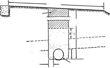
The standard underdrain consists of a perforated pipe near the bottom of a narrow trench. The trench is filled with a permeable material and may be lined with filter fabric if the trench is excavated in erodable soils. Figure 5.9 illustrates an underdrain used to intercept sidehill seepage.
The following considerations apply to the design of subsurface drainage:
1. Surface drainage should not be allowed to discharge into the subsurface drainage system.
2. Outlets for the underdrain system should be provided for at intervals not exceeding 500 ft (150 m) to 1000 ft (300 m), depending upon the porosity of the base course.
![]()
 Impervious Zone
3"min. ^6" Min. Diameter Pipe
FIGURE 5.9 Intercepting drain in impervious zone for keeping free water out of roadway and subgrade. Conversion: 1 in = 25.4 mm. (From Handbook of Steel Drainage and Highway Construction Products, American Iron and Steel Institute, 1994, with permission)
Outlet may run into the storm drain system as long as there is no possibility of backflow due to a buildup of hydrostatic pressure.
3. Pipe underdrains should be placed on grades steeper than 0.5 percent if possible. Minimum grades of 0.2 percent are acceptable.
4. The depth of the underdrain will depend upon the permeability of the soil, the elevation of the aquifer, and the amount of necessary drawdown to achieve stability.
5. Pipes for underdrains may be made of metal, plastic, concrete, clay, asbestos cement, or bituminous fiber. Two types of openings are used to allow the groundwater into the pipe: perforated and open-jointed. Open-jointed pipes such as clay and concrete drain tiles are limited to areas where the admission of excessive solids through the joints may be avoided.
(See “Pavement Subsurface Drainage Design,” FHWA-NHI-99-028, and “Pavement
Subsurface Drainage Systems,” NCHRP Synthesis 239, TRB, 1997.)


Leave a reply